Trob l Shooting x Cu
108
© Siemens AG The reproduction, transmission or use of this document or its contents is not permitted without express written authority. Offenders will be liable for damages. All rights, including rights created by patent grant or registration of a utility model or design, are reserved. Print No.: E r l w e i n POLYDOROS SX 65/80 POLYDOROS SX Troubleshooting Guide AX 2001 RX63-055.840.01.03.02 Replaces: RX63-055.840.01.02.02 English Doc. Gen. Date: 10.04 PL SX 03774119 05658385
description
XCU siemens
Transcript of Trob l Shooting x Cu
Erlwein
POLYDOROS SX 65/80
POLYDOROS SX
Troubleshooting Guide
© Siemens AGThe reproduction, traof this document or ipermitted without authority. Offenders damages. All rightscreated by patent graof a utility model
AX
ntse
w, no
smission or use
2001
contents is notxpress writtenill be liable forincluding rightst or registrationr design, are
Print No.: RX63-055.840.01.03.02Replaces: RX63-055.840.01.02.02
reserved.
EnglishDoc. Gen. Date: 10.04
PL SX
0377411905658385
2 Revision / Disclaimer
1Revision / Disclaimer
Document revision level
The document corresponds to the version/revision level effective at the time of system delivery. Revisions to hardcopy documentation are not automatically distributed.
Please contact your local Siemens office to order current revision levels.
Disclaimer
The installation and service of equipment described herein is to be performed by qualified personnel who are employed by Siemens or one of its affiliates or who are otherwise authorized by Siemens or one of its affiliates to provide such services.
Assemblers and other persons who are not employed by or otherwise directly affiliated with or authorized by Siemens or one of its affiliates are directed to contact one of the local offices of Siemens or one of its affiliates before attempting installation or service pro-cedures.
POLYDOROS SX 65/80 RX63-055.840.01.03.02 Siemens AG10.04 CSPS 211
Page 2 of 108Medical Solutions
Table of Contents 3
1- 0Table of Contents
1 _______ General ________________________________________________________ 6
Product-specific Remarks. . . . . . . . . . . . . . . . . . . . . . . . . . . . . . . . . . . . . . . . . . . . . . . . . 6Required Documents . . . . . . . . . . . . . . . . . . . . . . . . . . . . . . . . . . . . . . . . . . . . . . . . . 6Required Tools and Measurement Equipment . . . . . . . . . . . . . . . . . . . . . . . . . . . . . . 6Safety Information . . . . . . . . . . . . . . . . . . . . . . . . . . . . . . . . . . . . . . . . . . . . . . . . . . . 6Safety Precautions . . . . . . . . . . . . . . . . . . . . . . . . . . . . . . . . . . . . . . . . . . . . . . . . . . . 6kV, mAs and tube current tolerances . . . . . . . . . . . . . . . . . . . . . . . . . . . . . . . . . . . . . 7
Abbreviations and symbols used . . . . . . . . . . . . . . . . . . . . . . . . . . . . . . . . . . . . . . . . . . . 8
2 _______ Troubleshooting ________________________________________________ 9
Error 000. . . . . . . . . . . . . . . . . . . . . . . . . . . . . . . . . . . . . . . . . . . . . . . . . . . . . . . . . . . . . . 9
Error 001. . . . . . . . . . . . . . . . . . . . . . . . . . . . . . . . . . . . . . . . . . . . . . . . . . . . . . . . . . . . . 10
Error 002. . . . . . . . . . . . . . . . . . . . . . . . . . . . . . . . . . . . . . . . . . . . . . . . . . . . . . . . . . . . . 11
Error 003. . . . . . . . . . . . . . . . . . . . . . . . . . . . . . . . . . . . . . . . . . . . . . . . . . . . . . . . . . . . . 12
Error 004. . . . . . . . . . . . . . . . . . . . . . . . . . . . . . . . . . . . . . . . . . . . . . . . . . . . . . . . . . . . . 13
Error 007. . . . . . . . . . . . . . . . . . . . . . . . . . . . . . . . . . . . . . . . . . . . . . . . . . . . . . . . . . . . . 14
Error 051. . . . . . . . . . . . . . . . . . . . . . . . . . . . . . . . . . . . . . . . . . . . . . . . . . . . . . . . . . . . . 15
Error 052. . . . . . . . . . . . . . . . . . . . . . . . . . . . . . . . . . . . . . . . . . . . . . . . . . . . . . . . . . . . . 16
Error 053. . . . . . . . . . . . . . . . . . . . . . . . . . . . . . . . . . . . . . . . . . . . . . . . . . . . . . . . . . . . . 17
Error 054. . . . . . . . . . . . . . . . . . . . . . . . . . . . . . . . . . . . . . . . . . . . . . . . . . . . . . . . . . . . . 18
Error 055. . . . . . . . . . . . . . . . . . . . . . . . . . . . . . . . . . . . . . . . . . . . . . . . . . . . . . . . . . . . . 19
Error 056. . . . . . . . . . . . . . . . . . . . . . . . . . . . . . . . . . . . . . . . . . . . . . . . . . . . . . . . . . . . . 20
Error 057. . . . . . . . . . . . . . . . . . . . . . . . . . . . . . . . . . . . . . . . . . . . . . . . . . . . . . . . . . . . . 21
Error 058. . . . . . . . . . . . . . . . . . . . . . . . . . . . . . . . . . . . . . . . . . . . . . . . . . . . . . . . . . . . . 22
Error 077. . . . . . . . . . . . . . . . . . . . . . . . . . . . . . . . . . . . . . . . . . . . . . . . . . . . . . . . . . . . . 23
Error 100. . . . . . . . . . . . . . . . . . . . . . . . . . . . . . . . . . . . . . . . . . . . . . . . . . . . . . . . . . . . . 24
Error 119. . . . . . . . . . . . . . . . . . . . . . . . . . . . . . . . . . . . . . . . . . . . . . . . . . . . . . . . . . . . . 25
Error 120. . . . . . . . . . . . . . . . . . . . . . . . . . . . . . . . . . . . . . . . . . . . . . . . . . . . . . . . . . . . . 26
Error 121. . . . . . . . . . . . . . . . . . . . . . . . . . . . . . . . . . . . . . . . . . . . . . . . . . . . . . . . . . . . . 27
Error 122. . . . . . . . . . . . . . . . . . . . . . . . . . . . . . . . . . . . . . . . . . . . . . . . . . . . . . . . . . . . . 28
Error 123. . . . . . . . . . . . . . . . . . . . . . . . . . . . . . . . . . . . . . . . . . . . . . . . . . . . . . . . . . . . . 29
Error 125. . . . . . . . . . . . . . . . . . . . . . . . . . . . . . . . . . . . . . . . . . . . . . . . . . . . . . . . . . . . . 30
Error 401. . . . . . . . . . . . . . . . . . . . . . . . . . . . . . . . . . . . . . . . . . . . . . . . . . . . . . . . . . . . . 31
Error 402. . . . . . . . . . . . . . . . . . . . . . . . . . . . . . . . . . . . . . . . . . . . . . . . . . . . . . . . . . . . . 32
Error 403. . . . . . . . . . . . . . . . . . . . . . . . . . . . . . . . . . . . . . . . . . . . . . . . . . . . . . . . . . . . . 33
Error 404. . . . . . . . . . . . . . . . . . . . . . . . . . . . . . . . . . . . . . . . . . . . . . . . . . . . . . . . . . . . . 34
Error 410. . . . . . . . . . . . . . . . . . . . . . . . . . . . . . . . . . . . . . . . . . . . . . . . . . . . . . . . . . . . . 35
Error 413. . . . . . . . . . . . . . . . . . . . . . . . . . . . . . . . . . . . . . . . . . . . . . . . . . . . . . . . . . . . . 36
Error 421. . . . . . . . . . . . . . . . . . . . . . . . . . . . . . . . . . . . . . . . . . . . . . . . . . . . . . . . . . . . . 37
Error 422. . . . . . . . . . . . . . . . . . . . . . . . . . . . . . . . . . . . . . . . . . . . . . . . . . . . . . . . . . . . . 38
Siemens AG RX63-055.840.01.03.02 POLYDOROS SX 65/8010.04 CSPS 211
Page 3 of 108Medical Solutions
4 Table of Contents
Error 425 . . . . . . . . . . . . . . . . . . . . . . . . . . . . . . . . . . . . . . . . . . . . . . . . . . . . . . . . . . . . . 39
Error 426 . . . . . . . . . . . . . . . . . . . . . . . . . . . . . . . . . . . . . . . . . . . . . . . . . . . . . . . . . . . . . 40
Error 427 . . . . . . . . . . . . . . . . . . . . . . . . . . . . . . . . . . . . . . . . . . . . . . . . . . . . . . . . . . . . . 41
Error 428 . . . . . . . . . . . . . . . . . . . . . . . . . . . . . . . . . . . . . . . . . . . . . . . . . . . . . . . . . . . . . 42
Error 433 . . . . . . . . . . . . . . . . . . . . . . . . . . . . . . . . . . . . . . . . . . . . . . . . . . . . . . . . . . . . . 43
Error 434 . . . . . . . . . . . . . . . . . . . . . . . . . . . . . . . . . . . . . . . . . . . . . . . . . . . . . . . . . . . . . 44
Error 485 . . . . . . . . . . . . . . . . . . . . . . . . . . . . . . . . . . . . . . . . . . . . . . . . . . . . . . . . . . . . . 45
Error 486 . . . . . . . . . . . . . . . . . . . . . . . . . . . . . . . . . . . . . . . . . . . . . . . . . . . . . . . . . . . . . 46
Error 487 . . . . . . . . . . . . . . . . . . . . . . . . . . . . . . . . . . . . . . . . . . . . . . . . . . . . . . . . . . . . . 47
Error 488 . . . . . . . . . . . . . . . . . . . . . . . . . . . . . . . . . . . . . . . . . . . . . . . . . . . . . . . . . . . . . 48
Error 505 . . . . . . . . . . . . . . . . . . . . . . . . . . . . . . . . . . . . . . . . . . . . . . . . . . . . . . . . . . . . . 49
Error 510 . . . . . . . . . . . . . . . . . . . . . . . . . . . . . . . . . . . . . . . . . . . . . . . . . . . . . . . . . . . . . 50
Error 511 . . . . . . . . . . . . . . . . . . . . . . . . . . . . . . . . . . . . . . . . . . . . . . . . . . . . . . . . . . . . . 51
Error 512 . . . . . . . . . . . . . . . . . . . . . . . . . . . . . . . . . . . . . . . . . . . . . . . . . . . . . . . . . . . . . 52
Error 513 . . . . . . . . . . . . . . . . . . . . . . . . . . . . . . . . . . . . . . . . . . . . . . . . . . . . . . . . . . . . . 53
Error 515 . . . . . . . . . . . . . . . . . . . . . . . . . . . . . . . . . . . . . . . . . . . . . . . . . . . . . . . . . . . . . 54
Error 550 . . . . . . . . . . . . . . . . . . . . . . . . . . . . . . . . . . . . . . . . . . . . . . . . . . . . . . . . . . . . . 55
Error 551 . . . . . . . . . . . . . . . . . . . . . . . . . . . . . . . . . . . . . . . . . . . . . . . . . . . . . . . . . . . . . 56
Error 552 . . . . . . . . . . . . . . . . . . . . . . . . . . . . . . . . . . . . . . . . . . . . . . . . . . . . . . . . . . . . . 57
Error 560 . . . . . . . . . . . . . . . . . . . . . . . . . . . . . . . . . . . . . . . . . . . . . . . . . . . . . . . . . . . . . 58
Error 561 . . . . . . . . . . . . . . . . . . . . . . . . . . . . . . . . . . . . . . . . . . . . . . . . . . . . . . . . . . . . . 59
Error 562 . . . . . . . . . . . . . . . . . . . . . . . . . . . . . . . . . . . . . . . . . . . . . . . . . . . . . . . . . . . . . 60
Error 563 . . . . . . . . . . . . . . . . . . . . . . . . . . . . . . . . . . . . . . . . . . . . . . . . . . . . . . . . . . . . . 61
Error 570 . . . . . . . . . . . . . . . . . . . . . . . . . . . . . . . . . . . . . . . . . . . . . . . . . . . . . . . . . . . . . 62
Error 571 . . . . . . . . . . . . . . . . . . . . . . . . . . . . . . . . . . . . . . . . . . . . . . . . . . . . . . . . . . . . . 63
Error 572 . . . . . . . . . . . . . . . . . . . . . . . . . . . . . . . . . . . . . . . . . . . . . . . . . . . . . . . . . . . . . 64
Error 573 . . . . . . . . . . . . . . . . . . . . . . . . . . . . . . . . . . . . . . . . . . . . . . . . . . . . . . . . . . . . . 65
Error 575 . . . . . . . . . . . . . . . . . . . . . . . . . . . . . . . . . . . . . . . . . . . . . . . . . . . . . . . . . . . . . 66
Error 580 . . . . . . . . . . . . . . . . . . . . . . . . . . . . . . . . . . . . . . . . . . . . . . . . . . . . . . . . . . . . . 67
Error 581 . . . . . . . . . . . . . . . . . . . . . . . . . . . . . . . . . . . . . . . . . . . . . . . . . . . . . . . . . . . . . 68
Error 582 . . . . . . . . . . . . . . . . . . . . . . . . . . . . . . . . . . . . . . . . . . . . . . . . . . . . . . . . . . . . . 69
Error 590 . . . . . . . . . . . . . . . . . . . . . . . . . . . . . . . . . . . . . . . . . . . . . . . . . . . . . . . . . . . . . 70
Error 591 . . . . . . . . . . . . . . . . . . . . . . . . . . . . . . . . . . . . . . . . . . . . . . . . . . . . . . . . . . . . . 71
Error 600 . . . . . . . . . . . . . . . . . . . . . . . . . . . . . . . . . . . . . . . . . . . . . . . . . . . . . . . . . . . . . 72
Error 601 . . . . . . . . . . . . . . . . . . . . . . . . . . . . . . . . . . . . . . . . . . . . . . . . . . . . . . . . . . . . . 73
Error 602 . . . . . . . . . . . . . . . . . . . . . . . . . . . . . . . . . . . . . . . . . . . . . . . . . . . . . . . . . . . . . 74
Error 603 . . . . . . . . . . . . . . . . . . . . . . . . . . . . . . . . . . . . . . . . . . . . . . . . . . . . . . . . . . . . . 75
Error 604 . . . . . . . . . . . . . . . . . . . . . . . . . . . . . . . . . . . . . . . . . . . . . . . . . . . . . . . . . . . . . 76
Error 605 . . . . . . . . . . . . . . . . . . . . . . . . . . . . . . . . . . . . . . . . . . . . . . . . . . . . . . . . . . . . . 77
Error 606 . . . . . . . . . . . . . . . . . . . . . . . . . . . . . . . . . . . . . . . . . . . . . . . . . . . . . . . . . . . . . 78
POLYDOROS SX 65/80 RX63-055.840.01.03.02 Siemens AG10.04 CSPS 211
Page 4 of 108Medical Solutions
Table of Contents 5
Error 608. . . . . . . . . . . . . . . . . . . . . . . . . . . . . . . . . . . . . . . . . . . . . . . . . . . . . . . . . . . . . 79
Error 610. . . . . . . . . . . . . . . . . . . . . . . . . . . . . . . . . . . . . . . . . . . . . . . . . . . . . . . . . . . . . 80
Error 611. . . . . . . . . . . . . . . . . . . . . . . . . . . . . . . . . . . . . . . . . . . . . . . . . . . . . . . . . . . . . 81
Error 612. . . . . . . . . . . . . . . . . . . . . . . . . . . . . . . . . . . . . . . . . . . . . . . . . . . . . . . . . . . . . 82
Error 628. . . . . . . . . . . . . . . . . . . . . . . . . . . . . . . . . . . . . . . . . . . . . . . . . . . . . . . . . . . . . 83
Error 629. . . . . . . . . . . . . . . . . . . . . . . . . . . . . . . . . . . . . . . . . . . . . . . . . . . . . . . . . . . . . 84
Error 633. . . . . . . . . . . . . . . . . . . . . . . . . . . . . . . . . . . . . . . . . . . . . . . . . . . . . . . . . . . . . 85
Error 650. . . . . . . . . . . . . . . . . . . . . . . . . . . . . . . . . . . . . . . . . . . . . . . . . . . . . . . . . . . . . 86
Error 666. . . . . . . . . . . . . . . . . . . . . . . . . . . . . . . . . . . . . . . . . . . . . . . . . . . . . . . . . . . . . 87
Error 688. . . . . . . . . . . . . . . . . . . . . . . . . . . . . . . . . . . . . . . . . . . . . . . . . . . . . . . . . . . . . 88
Error 690. . . . . . . . . . . . . . . . . . . . . . . . . . . . . . . . . . . . . . . . . . . . . . . . . . . . . . . . . . . . . 89
Error 711. . . . . . . . . . . . . . . . . . . . . . . . . . . . . . . . . . . . . . . . . . . . . . . . . . . . . . . . . . . . . 90
Error 712. . . . . . . . . . . . . . . . . . . . . . . . . . . . . . . . . . . . . . . . . . . . . . . . . . . . . . . . . . . . . 93
Error 713. . . . . . . . . . . . . . . . . . . . . . . . . . . . . . . . . . . . . . . . . . . . . . . . . . . . . . . . . . . . . 94
Error 714. . . . . . . . . . . . . . . . . . . . . . . . . . . . . . . . . . . . . . . . . . . . . . . . . . . . . . . . . . . . . 95
Error 715. . . . . . . . . . . . . . . . . . . . . . . . . . . . . . . . . . . . . . . . . . . . . . . . . . . . . . . . . . . . . 96
Error 716. . . . . . . . . . . . . . . . . . . . . . . . . . . . . . . . . . . . . . . . . . . . . . . . . . . . . . . . . . . . . 97
Error 800. . . . . . . . . . . . . . . . . . . . . . . . . . . . . . . . . . . . . . . . . . . . . . . . . . . . . . . . . . . . . 98
Error 803. . . . . . . . . . . . . . . . . . . . . . . . . . . . . . . . . . . . . . . . . . . . . . . . . . . . . . . . . . . . . 99
Error 804. . . . . . . . . . . . . . . . . . . . . . . . . . . . . . . . . . . . . . . . . . . . . . . . . . . . . . . . . . . . 101
Error 805. . . . . . . . . . . . . . . . . . . . . . . . . . . . . . . . . . . . . . . . . . . . . . . . . . . . . . . . . . . . 102
Error 806. . . . . . . . . . . . . . . . . . . . . . . . . . . . . . . . . . . . . . . . . . . . . . . . . . . . . . . . . . . . 103
Error 810. . . . . . . . . . . . . . . . . . . . . . . . . . . . . . . . . . . . . . . . . . . . . . . . . . . . . . . . . . . . 104
Check of “Di Pulses” in XCS Network . . . . . . . . . . . . . . . . . . . . . . . . . . . . . . . . . . . . . 105Measurements in the XCS Cable Network . . . . . . . . . . . . . . . . . . . . . . . . . . . . . . . 105Measurements in the XCS Cable Network . . . . . . . . . . . . . . . . . . . . . . . . . . . . . . . 106
3 _______ Changes to Previous Version____________________________________ 108
Siemens AG RX63-055.840.01.03.02 POLYDOROS SX 65/8010.04 CSPS 211
Page 5 of 108Medical Solutions
6 General
2- 1GeneralProduct-specific Remarks 0
Required Documents 0
• Generator Wiring Diagram
• Startup instructions
Required Tools and Measurement Equipment 0
Safety Information 0
NOTE When carrying out the work steps and tests, the product-specificsafety information contained in the documents as well as the gen-eral safety information must be observed.
Safety Precautions 0
• Use the power OFF switch on board D 160 to switch off the generator before working on it .
WARNING Line voltage is still present in transformer T1 and switch-on circuitD 160 when the generator is switched off. After the generator isswitched off, approx. 600 V DC for the inverter is still present!
This is indicated by LEDs V35 and V36 on D110 and LED V89 on D220 goes on. The line voltage decays in approx. 1,5 minutes to 0 V; the LED’s go out when the voltage is approx. 30 V.
• Set the main system switch to OFF to switch off power to all components (generator and connected equipment).
• To avoid unintentional release of high voltage or radiation, switch OFF (S1) SS on the D100 board.
• Install or remove assemblies only with the generator switched off, and in accordance with ESD guidelines.
• Standard installation tool kit
• Service PC
• PC connection cable, 5 m 99 00 440
POLYDOROS SX 65/80 RX63-055.840.01.03.02 Siemens AG10.04 CSPS 211
Page 6 of 108Medical Solutions
General 7
WARNING Tests and adjustments that must be made with radiation switchedon are indicated by the radiation warning symbol x .
Take appropriate radiation protection measures when carrying out such work.
kV, mAs and tube current tolerances 0
NOTE All kV, mAs and tube current values are stated in these instruc-tions with ± 5% Tolerance.
Siemens AG RX63-055.840.01.03.02 POLYDOROS SX 65/8010.04 CSPS 211
Page 7 of 108Medical Solutions
8 General
Abbreviations and symbols used 0
Refer to the generator wiring diagram for further signal names.
ADC - Analog-digital converter
AP - Workstation selection
FL - Fluoroscopy
F0 - Large focal spot filament current
F1 - Small focal spot filament current
HS - High-voltage cable
HT - High-voltage generator
IGBT - Transistor (Insulated-Gate-Bipolar-Transistors)
LS - Charging contactor
LSR - Charging contactor relay
MPS - Serial interface (multiprocessor interface)
M_TK - Door contact
NAK - No acknowledgment
N-TU1 - Workstation switchover
OUTA - Actuation of bridge branch A
OUTB - Actuation of bridge branch B
PS - Power contactor
PSU - Powers contact acknowledgment
PSR - Power contactor relay
RANGE - Current range (ON / FL)
R-short - Jumper short-circuit
ROT - Rotating anode rotation
SNT - Switching power supply
STRSU - Tube assembly switchover in starter
UZ - Intermediate circuit voltage
WR - Inverter
ZB - Exposure preparation
POLYDOROS SX 65/80 RX63-055.840.01.03.02 Siemens AG10.04 CSPS 211
Page 8 of 108Medical Solutions
Troubleshooting 9
3- 2TroubleshootingError 000 0
Meaning:
Invalid Init Data
Description:
At least one init block is wrong. This error will be repeated at each following init block even if the init data of this block are correct. You may try to configure and select all fluoro curves new or configure the complete system from the scratch.
Siemens AG RX63-055.840.01.03.02 POLYDOROS SX 65/8010.04 CSPS 211
Page 9 of 108Medical Solutions

10 Troubleshooting
Error 001 0
Meaning:
Start of Service Session.
Description:
• The Service PC has contacted the XCU.
• No error, for information only.
• This error will be shown as error 41 of AP-ID 240 (XCU) in the errorlog.
POLYDOROS SX 65/80 RX63-055.840.01.03.02 Siemens AG10.04 CSPS 211
Page 10 of 108Medical Solutions
Troubleshooting 11
Error 002 0
Meaning:
End of Service Session.
Description:
• The Service PC has terminated the connection to the XCU (logged off).
• No error, for information only.
• This error will be shown as error 42 of AP-ID 240 (XCU) in the errorlog.
Siemens AG RX63-055.840.01.03.02 POLYDOROS SX 65/8010.04 CSPS 211
Page 11 of 108Medical Solutions
12 Troubleshooting
Error 003 0
Meaning:
Start of Remote Service Session.
Description:
• The Service PC has contacted the XCU via Modem.
• No error, for information only.
• This error will be shown as error 46 of AP-ID 240 (XCU) in the errorlog.
POLYDOROS SX 65/80 RX63-055.840.01.03.02 Siemens AG10.04 CSPS 211
Page 12 of 108Medical Solutions
Troubleshooting 13
Error 004 0
Meaning:
End of Remote Service Session.
Description:
• The Service PC has terminated the remote connection to the XCU (logged off).
• No error, for information only.
• This error will be shown as error 47 of AP-ID 240 (XCU) in the errorlog.
Siemens AG RX63-055.840.01.03.02 POLYDOROS SX 65/8010.04 CSPS 211
Page 13 of 108Medical Solutions
14 Troubleshooting
Error 007 0
Meaning:
Polydoros is no longer in the XCS-network.
Error 007 is most of the times accompanied by a 1 on the D100 in case of HW defects.
In case of SW-Resets 007 will heal itself.
Description:
The communication between Polydoros and XCU is down.
Possible reason:
• Checking the terminal connectors. At the terminal D320.X3.S and US or D320.X4.S and US, there must be either:
- 2 terminal connectors installed
- 1 terminal connector and 1 cable installed
- 2 cables installed
The terminal connector has Part No.: 3157174.
• Cable not connected from XCU to generator
• Cable has a short circuit
• Hybrid-circuit of ARCNET is defective on any XCS component
• SW of a component sends ARCNET Reconfiguration interrupts intermittently
• Watchdog of Polydoros is active
• D100 or power supply defective
Possible causes and action:
• Check cabling for connection and shorts
• Check Hybrids and terminators.
• D100, D200 defect, replace.
POLYDOROS SX 65/80 RX63-055.840.01.03.02 Siemens AG10.04 CSPS 211
Page 14 of 108Medical Solutions
Troubleshooting 15
Error 051 0
Meaning:
D100.J15 PROM checksum error (with D100 Part-No.: 37 75 256)
Description:
D100 checks the PROM"s check sum during initialization
Possible causes and action:
• PROM D100.J15 defekt (with D100 Part-No.: 37 75 256)
• D100 defect
Siemens AG RX63-055.840.01.03.02 POLYDOROS SX 65/8010.04 CSPS 211
Page 15 of 108Medical Solutions
16 Troubleshooting
Error 052 0
Meaning:
Heating-Error during download
Description:
D220 sends telegram "not acknowledge"
Possible causes and action:
• Repeat filament download
• Replace D220
POLYDOROS SX 65/80 RX63-055.840.01.03.02 Siemens AG10.04 CSPS 211
Page 16 of 108Medical Solutions
Troubleshooting 17
Error 053 0
Meaning:
Image intensifier: invalid zoom level
Description:
XCU sends zoom level > 3 to D100
Possible causes and action:
• Check configuration
Siemens AG RX63-055.840.01.03.02 POLYDOROS SX 65/8010.04 CSPS 211
Page 17 of 108Medical Solutions
18 Troubleshooting
Error 054 0
Meaning:
Invalid fluoro data
Description:
Probably the configuration has been modified without turn off/on the generator, so that an unknown fluoro curve has been selected, known to XCU but not yet known to the genera-tor. This might also be due to the fact that MANUAL.kV fluoroscopy is selected in systems supporting pulsed fluoroscopy.
POLYDOROS SX 65/80 RX63-055.840.01.03.02 Siemens AG10.04 CSPS 211
Page 18 of 108Medical Solutions
Troubleshooting 19
Error 055 0
Meaning:
Invalid parameters for characteristic kV curve
Description:
XCU sends characteristic kV curve with more than 10 points
Siemens AG RX63-055.840.01.03.02 POLYDOROS SX 65/8010.04 CSPS 211
Page 19 of 108Medical Solutions
20 Troubleshooting
Error 056 0
Meaning:
Invalid exposure mode
Description:
XCU sends request for impermissible mode of operation
POLYDOROS SX 65/80 RX63-055.840.01.03.02 Siemens AG10.04 CSPS 211
Page 20 of 108Medical Solutions
Troubleshooting 21
Error 057 0
Meaning:
Fluoro attachment feedback (signal DLR_U) wrong
Description:
With fluoroscopy the activation of the fluoroscopy relay (DLR_) is displayed on the D100.X50.5. This signal comes to D111.X50.5 and activates the relay K1. Through the activated relay contact of K1.1/2 the contactor K6 is activated and the fluoro attachment is added on (see wiring diagram X2206-16). The fluoro attachment feedback (DLR_U) is output via D111.X50.7 to D100.X50.7.
Possible causes and action:
• D100
• D111
• Contactor K6
• Ribbon cable X50
Siemens AG RX63-055.840.01.03.02 POLYDOROS SX 65/8010.04 CSPS 211
Page 21 of 108Medical Solutions
22 Troubleshooting
Error 058 0
Meaning:
Polydoros Host-SW is mismatching the type of generator configured in the XCS configu-rations-SW. E.g. D100 PROM is LX lite and configured type is LX 80.
Possibe causes and action:
• Configure the correct generator in the XCS service software
POLYDOROS SX 65/80 RX63-055.840.01.03.02 Siemens AG10.04 CSPS 211
Page 22 of 108Medical Solutions
Troubleshooting 23
Error 077 0
Meaning:
Timeout exposure release
Description:
HS trigger of image system (ASU) is missing during pulsed fluoroscopy or indirect tech-nique
Possible causes and action:
• Check of HS trigger
Siemens AG RX63-055.840.01.03.02 POLYDOROS SX 65/8010.04 CSPS 211
Page 23 of 108Medical Solutions
24 Troubleshooting
Error 100 0
Meaning:
Invalid task state D100
Description:
The software on the D100 is in an impermissible task state
Possible causes and action:
• PROM D100.J15 (for D100 Part No.: 37 75 256)
• D100
POLYDOROS SX 65/80 RX63-055.840.01.03.02 Siemens AG10.04 CSPS 211
Page 24 of 108Medical Solutions
Troubleshooting 25
Error 119 0
Meaning:
Time out filament circuit
Description:
The communikation between filament D220 and master D100 is made via serial link (MPS, D100.X1.28, D220.X1.28)
If an interruption of the communication between D100 and D200 occurs, Error 119 is out-put by D100.
Possible causes and action:
• Serial interface interrupted → check
• D100, D220 defetive → replace
• Arcing tube
• H1 High tension transformer
• Check screening and shielding of cabling
• Check protective ground wire, all protective ground wire connections intended by the manufacturer must be made.
• Check firmware level.
• Check voltage power supplies +5 V ± 0,2 V (on D100, D160 and D220).
• Check schematics of generator for LED’s.
• Ignore error 119, if the red LED (D220) is blinking and no firmware is loaded → perform download
Siemens AG RX63-055.840.01.03.02 POLYDOROS SX 65/8010.04 CSPS 211
Page 25 of 108Medical Solutions
26 Troubleshooting
Error 120 0
Meaning:
No communication vie D220 to D100 via serial line (transmit)
Description:
The communikation between filament D220 and master D100 is made via serial link (MPS, D100.X1.28, D220.X1.28)
In communication errors between D100 and D220, Error 120 is output by D100.
Possible causes and action:
• Serial interface interrupted → check
• D100, D220 defective → replace
• Arcing tube
• Check screening and shielding of cabling
• Check protective ground wire, all protective ground wire connections intended by the manufacturer must be made.
• Check firmware level.
• Check voltage power supplies +5 V ± 0,2 V (on D100, D160 and D220).
• Check schematics of generator for LED’s.
• Ignore error 120, if the red LED (D220) is blinking and no firmware is loaded → perform download.
POLYDOROS SX 65/80 RX63-055.840.01.03.02 Siemens AG10.04 CSPS 211
Page 26 of 108Medical Solutions
Troubleshooting 27
Error 121 0
Meaning:
No communication vie D220 to D100 via serial line (receive)
Description:
The communikation between filament D220 and master D100 is made via serial link (MPS, D100.X1.28, D220.X1.28)
In communication errors between D100 and D220, Error 121 is output by D100.
Possible causes and action:
• Serial interface interrupted → check
• D100, D220 defective → replace
• Arcing tube
• Check screening and shielding of cabling
• Check protective ground wire, all protective ground wire connections intended by the manufacturer must be made.
• Check firmware level.
• Check voltage power supplies +5 V ± 0,2 V (on D100, D160 and D220).
• Check schematics of generator for LED’s.
• Ignore error 121, if the red LED(D220) is blinking and no firmware is loaded → perform download.
Siemens AG RX63-055.840.01.03.02 POLYDOROS SX 65/8010.04 CSPS 211
Page 27 of 108Medical Solutions
28 Troubleshooting
Error 122 0
Meaning:
Buffer overflow in receive queue to filament
Description:
The communikation between filament D220 and master D100 is made via serial link (MPS, D100.X1.28, D220.X1.28)
In communication errors between D100 and D220, Error 122 is output by D100.
Possible causes and action:
• Serial interface interrupted → check
• D100, D220 defective → replace
• Arcing tube
• Check screening and shielding of cabling
• Check protective ground wire, all protective ground wire connections intended by the manufacturer must be made.
• Check firmware level.
• Check voltage power supplies +5 V ± 0,2 V (on D100, D160 and D220).
• Check schematics of generator for LED’s.
• Ignore error 122, if the red LED(D220) is blinking and no firmware is loaded → perform download.
POLYDOROS SX 65/80 RX63-055.840.01.03.02 Siemens AG10.04 CSPS 211
Page 28 of 108Medical Solutions
Troubleshooting 29
Error 123 0
Meaning:
Invalid answer from filament
Description:
The communikation between filament D220 and master D100 is made via serial link (MPS, D100.X1.28, D220.X1.28)
In communication errors between D100 and D220, Error 123 is output by D100.
Possible causes and action:
• Serial interface interrupted -> check
• D100, D220 defective → replace
• Arcing tube
• Check screening and shielding of cabling
• Check protective ground wire, all protective ground wire connections intended by the manufacturer must be made.
• Check firmware level.
• Check voltage power supplies +5 V ± 0,2 V(on D100, D160 and D220).
• Check schematics of generator for LED’s.
• Ignore error 123, if the red LED(D220) is blinking and no firmware is loaded → perform download.
Siemens AG RX63-055.840.01.03.02 POLYDOROS SX 65/8010.04 CSPS 211
Page 29 of 108Medical Solutions
30 Troubleshooting
Error 125 0
Meaning:
Timeout Iontomat
Possible causes and action:
• Check cabling from D100 to Iontomat or replace cable
POLYDOROS SX 65/80 RX63-055.840.01.03.02 Siemens AG10.04 CSPS 211
Page 30 of 108Medical Solutions
Troubleshooting 31
Error 401 0
Meaning:
Time-out ADC of filament circuit
Description:
A/D converter in the filament circuit does not convert
Possible causes and action:
• Measure Vcc = +5 V ± 0,2 Volt on D220.X18.A1
• If voltage is within tolerance, replace board D220
Siemens AG RX63-055.840.01.03.02 POLYDOROS SX 65/8010.04 CSPS 211
Page 31 of 108Medical Solutions
32 Troubleshooting
Error 402 0
Meaning:
Minimum filament current
Description:
The minimum filament current (=1/2 nominal value) is monitored in standby.
Possible causes and action:
• Intermediate circuit voltage missing in the filament circuit at X41.7 and X41.10, mearure 230V ± 10%.
• Check fuse F21, D160
• Interruption in the filament path:
- Check wiring X41 - H1
- Workstation selected, AP relay in H1 actuated
1. H1 test point 50 = 0V
2. Ap 1 test point 51 = 24V (±15%)
3. AP2 test point 52 = 24V (±15%)
• Check filament transformer primäry winding (R < 1Ohm, transformation ratio 32:9)
• Check filament and high-voltage cable
• If no error is found, replace board D220.
POLYDOROS SX 65/80 RX63-055.840.01.03.02 Siemens AG10.04 CSPS 211
Page 32 of 108Medical Solutions
Troubleshooting 33
Error 403 0
Meaning:
Maximum tube current in radiography
Description:
The tube current is exceeded by 50% 100 ms after high voltage ON.
Possible causes and action:
Perform tube adjust
Siemens AG RX63-055.840.01.03.02 POLYDOROS SX 65/8010.04 CSPS 211
Page 33 of 108Medical Solutions
34 Troubleshooting
Error 404 0
Meaning:
Maximum tube current in fluoroscopy
Description:
The tube current is exceeded by 50% 100 ms after high voltage ON
Possible causes and action:
Perform tube adjust
POLYDOROS SX 65/80 RX63-055.840.01.03.02 Siemens AG10.04 CSPS 211
Page 34 of 108Medical Solutions
Troubleshooting 35
Error 410 0
Meaning:
Timeout processor
Possible causes and action:
• Check power supply on D220:
- V66 = -15V (±10%)
- V65 = +15V (±10%)
- V64 = +15V (±10%)
- X19/A8 = +24V (±15%)
• Replace D220
Siemens AG RX63-055.840.01.03.02 POLYDOROS SX 65/8010.04 CSPS 211
Page 35 of 108Medical Solutions
36 Troubleshooting
Error 413 0
Meaning:
Tube current nominal value to large.
Possible causes and action:
• Error in the master → perform system configuration and POLYDOROS adjustment.
• Replace D220
POLYDOROS SX 65/80 RX63-055.840.01.03.02 Siemens AG10.04 CSPS 211
Page 36 of 108Medical Solutions
Troubleshooting 37
Error 421 0
Meaning:
Wrong tube current value in fluoroscopy
Possible causes and action:
Error in the master → perform system configuration and POLYDOROS adjustment.
Siemens AG RX63-055.840.01.03.02 POLYDOROS SX 65/8010.04 CSPS 211
Page 37 of 108Medical Solutions
38 Troubleshooting
Error 422 0
Meaning:
Maximum filament current in tube current control
Description:
The tube current control permits a filament current of 1,25 times the max. filament current for 200 ms. If the controller finds no adjustment with max. filament current after this time, a warning is sent to the notice memory.
Possible causes and action:
• Check the filament current with cathotest
• The tube is not adjusted correctly
• The tube emits verly badly
• Perform tube adjust
• Check filament transformer primäry winding (R < 1Ohm, transformation ratio 32:9)
POLYDOROS SX 65/80 RX63-055.840.01.03.02 Siemens AG10.04 CSPS 211
Page 38 of 108Medical Solutions

Troubleshooting 39
Error 425 0
Meaning:
-15V (±10%) is less than -12V on D220
Possible causes and action:
• Check voltage at D220.V66 -15V (±10%)
• Check connection to D100 (lead X1.12; X1.38-40)
• Check voltage on D160, Checkpoints:
- X30 = -15V (±10%)
- X29 = +15V (±10%)
- X28 = 0V
Siemens AG RX63-055.840.01.03.02 POLYDOROS SX 65/8010.04 CSPS 211
Page 39 of 108Medical Solutions
40 Troubleshooting
Error 426 0
Meaning:
15V analog (± 10%) is less than 12V on D220
Possible causes and action:
• Check voltage at D220.V65 for +15V (± 10%)
• Check connection to D100 (lead X1.10, X1.38-40)
• Check voltage on D160, Checkpoints:
- X30 = -15V (± 10%)
- X29 = +15V (± 10%)
- X28 = 0V
POLYDOROS SX 65/80 RX63-055.840.01.03.02 Siemens AG10.04 CSPS 211
Page 40 of 108Medical Solutions
Troubleshooting 41
Error 427 0
Meaning:
15V digital (± 10%) is less than 12V on D220.
Possible causes and action:
• Check D220.V64 for +15V (± 10%)
• Check connection to D100 (lead X1.22, X1.38-40)
• Check voltage on D160, Checkpoints:
- X30 = -15V (± 10%)
- X29 = +15V (± 10%)
- X28 = 0V
Siemens AG RX63-055.840.01.03.02 POLYDOROS SX 65/8010.04 CSPS 211
Page 41 of 108Medical Solutions
42 Troubleshooting
Error 428 0
Meaning:
24V (± 15%) is less than 20V on D220
Possible causes and action:
• Check voltage on D220.X19.A8 24V (± 15%)
• Check connection to D100 (lead X1.21, X1.38-40)
• Check voltage on D160:
- D160.X13/14 = 24V (± 15%)
- D160.X28 = 0V
• It might as well be the case that the power fail signal X1 on D320 is not detected and therefore, each time you switch on, the error is entered into the error log.
• Input check: Remove cable D160.X1 coming from D320. The Hex display on D320 should indicate "F4". If not, D320 is defective.
• Output check: Connect a voltmeter (DC) to D160.X121.2 (power fail) and X121.1; when switching off the generator, voltage should suddenly change from 5 V to 0 V.
• A defective heating circuit fan (24 V power supply) above the D220 can be the cause for dropping below the 24 V monitoring.
POLYDOROS SX 65/80 RX63-055.840.01.03.02 Siemens AG10.04 CSPS 211
Page 42 of 108Medical Solutions
Troubleshooting 43
Error 433 0
Meaning:
Current in the filament inverter F0 (large focal spot) too high
Possible causes and action:
• Short circuit in the charging circuit
• Wiring X41, filament transformer, high-voltage cable, filament or D220 defective.
• Eject leads X41.3 and X41.11
- if error 433 occurs anew after reset, D220 must be replaced
- if error 402 occurs, D220 is OK
• Check filament transformer. Primary winding R < 1Ohm, transformation ratio 32:9
Siemens AG RX63-055.840.01.03.02 POLYDOROS SX 65/8010.04 CSPS 211
Page 43 of 108Medical Solutions
44 Troubleshooting
Error 434 0
Meaning:
Current in the filament inverter F1 (small focal spot) too high
Possible causes and action:
• Short circuit in the charging circuit
• Wiring X41, filament transformer, high-voltage cable, filament or D220 defective.
• Eject leads X41.9 and X41.12
- if error 434 occurs anew after reset, D220 must be replaced
- if error 402 occurs, D220 is OK
• Check filament transformer. Primary winding R < 1Ohm, transformation ratio 32:9
POLYDOROS SX 65/80 RX63-055.840.01.03.02 Siemens AG10.04 CSPS 211
Page 44 of 108Medical Solutions
Troubleshooting 45
Error 485 0
Meaning:
Filament download: error when deleting Flash-Prom
Possible causes and action:
• Repeat filament download
• D220
Siemens AG RX63-055.840.01.03.02 POLYDOROS SX 65/8010.04 CSPS 211
Page 45 of 108Medical Solutions

46 Troubleshooting
Error 486 0
Meaning:
Filament download: error in check sum of the Flash-PROM
Possible causes and action:
• Repeat filament download
• D220
POLYDOROS SX 65/80 RX63-055.840.01.03.02 Siemens AG10.04 CSPS 211
Page 46 of 108Medical Solutions

Troubleshooting 47
Error 487 0
Meaning:
Filament download: Error by bank switching
Possible causes and action:
• Repeat filament download
• D220
Siemens AG RX63-055.840.01.03.02 POLYDOROS SX 65/8010.04 CSPS 211
Page 47 of 108Medical Solutions
48 Troubleshooting
Error 488 0
Meaning:
Filament download: Error during programming Flash-Proming
Possible causes and action:
• Repeat filament download
• D220
POLYDOROS SX 65/80 RX63-055.840.01.03.02 Siemens AG10.04 CSPS 211
Page 48 of 108Medical Solutions
Troubleshooting 49
Error 505 0
Meaning:
Invalid iontomat configuration
Description:
Storage of configuration data into D190 RAM is not possible
Possible causes and action:
• D190
Siemens AG RX63-055.840.01.03.02 POLYDOROS SX 65/8010.04 CSPS 211
Page 49 of 108Medical Solutions
50 Troubleshooting
Error 510 0
Meaning:
Inadmissible IONTOMAT workstation
Description:
After selection of an iontomated operating mode or fluoroscopy, a check is made whether a permissible IONTOMAT workstation has been transferred by the master D100.
In the event of an error, no or a wrong workstation is output.
Possible causes and action:
• Check system configuration
• Are the IONTOMAT workstations correctly programmed?
POLYDOROS SX 65/80 RX63-055.840.01.03.02 Siemens AG10.04 CSPS 211
Page 50 of 108Medical Solutions
Troubleshooting 51
Error 511 0
Meaning:
Iontomat: Impermissible film-screen system
Description:
After selecting an iontomatized mode of operation the Iontomat checks whether or not the film-screen system (H, U, D) transferred to it is permissible. If no, several or a wrong film-screen system were transferred, Error 511 is displayed.
Possible causes and action:
• Check system configuration
• D190
Siemens AG RX63-055.840.01.03.02 POLYDOROS SX 65/8010.04 CSPS 211
Page 51 of 108Medical Solutions
52 Troubleshooting
Error 512 0
Meaning:
Iontomat: invalid tomo time selection
Description:
After selecting the Plani-Iontomat mode of operation, the Iontomat checks whether or not the selected tomographic time is permissible. If the transferred tomographic time was too long or too short, Error 512 is displayed.
Possible causes and action:
• Check system configuration
• D190
POLYDOROS SX 65/80 RX63-055.840.01.03.02 Siemens AG10.04 CSPS 211
Page 52 of 108Medical Solutions
Troubleshooting 53
Error 513 0
Meaning:
Iontomat: invalid detector
Description:
After selecting a iontomatized mode of operation or fluoroscopy the Iontomat checks whether or not the detector stored in EEPROM is permissible.
Possible causes and action:
• Check system configuration
• D190
Siemens AG RX63-055.840.01.03.02 POLYDOROS SX 65/8010.04 CSPS 211
Page 53 of 108Medical Solutions

54 Troubleshooting
Error 515 0
Meaning:
Iontomat: impermissible plug position
Description:
After selecting a iontomatized mode of operation it is checked whether or not the plug position stored in EEPROM is permissible..
Possible causes and action:
• Check system configuration
• D190
POLYDOROS SX 65/80 RX63-055.840.01.03.02 Siemens AG10.04 CSPS 211
Page 54 of 108Medical Solutions
Troubleshooting 55
Error 550 0
Meaning:
Dose monitoring has responded, not enough dose detected after 100 ms
Description:
In an iontomated exposure, the dose counter on D100 is read after 100 ms exposure time. If one half of the necessary does is not reached by the max. exposure time, error 550 is signalled
Possible causes and action:
• Faulty operation (customer):
- Tube not directed onto selected IONTOMAT chamber
- Collimator closed
- Wrong choice of the exposure kV
• Errors:
- Wrong IONTOMAT workstation programmed, check system configuration
- No signal from IONTOMAT chamber at measuring point D100.X63 DL_IN
- Check detector and cabling
- D100 defective, replace
Siemens AG RX63-055.840.01.03.02 POLYDOROS SX 65/8010.04 CSPS 211
Page 55 of 108Medical Solutions
56 Troubleshooting
Error 551 0
Meaning:
Iontomat: Dose supervision min. for tomo
Description:
This error is similar to error 550 in normal mode. However the dose is not checked after 100 ms, but at the end of the tomo exposure. It can be caused as a follow-up error, if the object to be exposed, requires more mAs, than the generator is allowed to give. E.G. 800 mAs is max mAs. At 1.2 s tomo time max mA would be 666 mA. However the gener-ator may use 800 mA in order to have a reserve for the different angles and projections during the tomo turn. If the object is that thick, that the generator is using 800 mA all the 1.2 sec the 800 mAs will be reached after 1.0 s and the generator will stop X-raying. After 1.2 s it will state, that the dose was too low.
POLYDOROS SX 65/80 RX63-055.840.01.03.02 Siemens AG10.04 CSPS 211
Page 56 of 108Medical Solutions
Troubleshooting 57
Error 552 0
Meaning:
Iontomat: Dose supervision max. for tomo
Description:
Dose counter terminates exposure before the tomographic time ends
Possible causes and action:
• Select higher exposure parameters
Siemens AG RX63-055.840.01.03.02 POLYDOROS SX 65/8010.04 CSPS 211
Page 57 of 108Medical Solutions
58 Troubleshooting
Error 560 0
Meaning:
Iontomat: kV value impermissible
Possible causes and action:
• D190
POLYDOROS SX 65/80 RX63-055.840.01.03.02 Siemens AG10.04 CSPS 211
Page 58 of 108Medical Solutions
Troubleshooting 59
Error 561 0
Meaning:
Iontomat: invalid max time ( >10s)
Possible causes and action:
• D190
Siemens AG RX63-055.840.01.03.02 POLYDOROS SX 65/8010.04 CSPS 211
Page 59 of 108Medical Solutions
60 Troubleshooting
Error 562 0
Meaning:
Iontomat: invalid measuring field
Description:
No scan field selected
Possible causes and action:
• Check system configuration
• D190
POLYDOROS SX 65/80 RX63-055.840.01.03.02 Siemens AG10.04 CSPS 211
Page 60 of 108Medical Solutions
Troubleshooting 61
Error 563 0
Meaning:
Iontomat: Invalid fluoro detector (no PDA/MPL or B signal)
Possible causes and action:
• Check system configuration
Siemens AG RX63-055.840.01.03.02 POLYDOROS SX 65/8010.04 CSPS 211
Page 61 of 108Medical Solutions
62 Troubleshooting
Error 570 0
Meaning:
Iontomat: Checksum error detector
Possible causes and action:
• D190
POLYDOROS SX 65/80 RX63-055.840.01.03.02 Siemens AG10.04 CSPS 211
Page 62 of 108Medical Solutions
Troubleshooting 63
Error 571 0
Meaning:
Iontomat: Checksum error HUD
Possible causes and action:
• D190
Siemens AG RX63-055.840.01.03.02 POLYDOROS SX 65/8010.04 CSPS 211
Page 63 of 108Medical Solutions
64 Troubleshooting
Error 572 0
Meaning:
Iontomat: Checksum error lead time value
Possible causes and action:
• D190
POLYDOROS SX 65/80 RX63-055.840.01.03.02 Siemens AG10.04 CSPS 211
Page 64 of 108Medical Solutions
Troubleshooting 65
Error 573 0
Meaning:
Iontomat: Checksum error voltage correction
Possible causes and action:
• D190
Siemens AG RX63-055.840.01.03.02 POLYDOROS SX 65/8010.04 CSPS 211
Page 65 of 108Medical Solutions

66 Troubleshooting
Error 575 0
Meaning:
Iontomat: Checksum error density correction
Possible causes and action:
• D190
POLYDOROS SX 65/80 RX63-055.840.01.03.02 Siemens AG10.04 CSPS 211
Page 66 of 108Medical Solutions

Troubleshooting 67
Error 580 0
Meaning:
Iontomat: bad dose value
Possible causes and action:
• Check system configuration
• D190
Siemens AG RX63-055.840.01.03.02 POLYDOROS SX 65/8010.04 CSPS 211
Page 67 of 108Medical Solutions
68 Troubleshooting
Error 581 0
Meaning:
Iontomat: bad lead time value
Possible causes and action:
• Check system configuration
• D190
POLYDOROS SX 65/80 RX63-055.840.01.03.02 Siemens AG10.04 CSPS 211
Page 68 of 108Medical Solutions
Troubleshooting 69
Error 582 0
Meaning:
Iontomat: bad voltage correction
Possible causes and action:
• Check system configuration
• D190
Siemens AG RX63-055.840.01.03.02 POLYDOROS SX 65/8010.04 CSPS 211
Page 69 of 108Medical Solutions
70 Troubleshooting
Error 590 0
Meaning:
Iontomat: mAs value not sent
Possible causes and action:
• Check system configuration
• D190
• D100
POLYDOROS SX 65/80 RX63-055.840.01.03.02 Siemens AG10.04 CSPS 211
Page 70 of 108Medical Solutions

Troubleshooting 71
Error 591 0
Meaning:
Iontomat: bad tube AP selection
Possible causes and action:
• Check system configuration
Siemens AG RX63-055.840.01.03.02 POLYDOROS SX 65/8010.04 CSPS 211
Page 71 of 108Medical Solutions
72 Troubleshooting
Error 600 0
Meaning:
+15V (±10%) faulty
Possible causes and action:
• 5V ± 0,2V present?
• Short circuit on board D100, D220, D110
• LED V72 on D160 is not on, replace SNT power pack
• Check voltage on D160.X4.4 and X4.1 230V~ (± 10%), if present replace SNT power pack.
POLYDOROS SX 65/80 RX63-055.840.01.03.02 Siemens AG10.04 CSPS 211
Page 72 of 108Medical Solutions
Troubleshooting 73
Error 601 0
Meaning:
-15V faulty
Possible causes and action:
• Short circuit on board D100, D220
• LED V73 on board D160 is not on, replace SNT power pack
• Check voltage on D160.X4.4 and X4.1 230V~ (± 10%), if present replace SNT power pack.
Siemens AG RX63-055.840.01.03.02 POLYDOROS SX 65/8010.04 CSPS 211
Page 73 of 108Medical Solutions
74 Troubleshooting
Error 602 0
Meaning:
Power contactor (PS) not OK.
Description:
• On initialization:
- D100 switches the power contactor on and wait 0.5s for the acknowledgment. If this noes not occur, Error 602 is output.
• In operation:
- If the power contactor drops out during operation, Error 602 is also output.
Possible causes and action:
• Drive "Power-" relay defective (D160.K5), i.e. no low signal (0V) PSR at D160.X5.7
- D100 defective
• If the above named signal OK and the power contactor does not switch, relay K5 on D160 defective
- replace D160
• Check cable from D100.X5 to D160.X5
• Actuation of the PS contactor A2, A1
- 24V~ (± 10%) at 50 Hz
- 29V~ (± 10%) at 60 Hz
• Check contactor acknowledgment PSU at D100.X5.25 24V~ (± 10%)
• Contactor sticks or jams.
POLYDOROS SX 65/80 RX63-055.840.01.03.02 Siemens AG10.04 CSPS 211
Page 74 of 108Medical Solutions
Troubleshooting 75
Error 603 0
Meaning:
Charging contactor (LS) not OK
Description:
On initialization: D100 switches the charging contactor closed. There must be an acknowl-edgment after 5 s, otherwise Error 603 is output.
Possible causes and action:
• Actuation of "charging" relay D160.K4 defective, i.e. no low signal (0V) LSR at D160.X5.5
- D100 defective
• If the above named signal is OK and K4 does not switch, relay K4 on D160defective
- replace D160
• Check cable from D100.X5 to D160.X5
• Check actuation of the LS contactor A2, A1
- 24V~ (± 10%) at 50 Hz
- 29V~ (± 10%) at 60 Hz
• Check contactor acknowledgment LSU at D100.X5.27 or D160.X3.9 24V~ (± 15%).
• Contactor sticks or jams.
Siemens AG RX63-055.840.01.03.02 POLYDOROS SX 65/8010.04 CSPS 211
Page 75 of 108Medical Solutions
76 Troubleshooting
Error 604 0
Meaning:
Intermediate circuit voltage (UZ) < 400V.
UZACT = 1.4 x Umains
Caution! Direct voltage
Description:
• On initialization:
- The charging contactor is switched in by D160. The status of the intermediate circuit voltage is queried after 5s (provided there has been a charging contactor acknowl-edgment). At a too low intermediate circuit voltage, (< 400V), Error 604 is output.
• In operation:
- If the intermediate circuit voltage drops during operation, Error 604 is also output.
Possible causes and action:
• Phase is missing, intermediate circuit is charged too slowly
• Check line voltages
• Check the UZACT signal on D100.X20.17 and X20.19 (1V 50V / UZACT = 1.4 x ULine)
• Check ribbon cable from D100.X20 to D115.X20
• R1, R2, R3, R4 load resistors defective; replace the resistors.
POLYDOROS SX 65/80 RX63-055.840.01.03.02 Siemens AG10.04 CSPS 211
Page 76 of 108Medical Solutions
Troubleshooting 77
Error 605 0
Meaning:
Intermediate circuit voltage (UZ) > 630V.
UZACT = 1.4 x Umains
Caution! Direct voltage
Description:
On initialization: The charging contactor is switched in by D160. The status of the interme-diate circuit voltage is queried after 5 s (provided there has been a charging contactor acknowledgment). At a too high intermediate circuit voltage, (> 630 V), Error 605 is out-put.
Possible causes and action:
• Check line voltages
• Measuring the line resistance
• Check UZACT Signal at D100.X20.17 and X20.19 (UZACT = 1,4 x Umains)
• Check ribbon cable from D100.X20 to D115.X20
Siemens AG RX63-055.840.01.03.02 POLYDOROS SX 65/8010.04 CSPS 211
Page 77 of 108Medical Solutions
78 Troubleshooting
Error 606 0
Meaning:
RANGE Error
Description:
The signals RANGE0 "OK" and RANGE1 "OK" monitor the switchover of the tube current measuring ranges on D220. The corresponding relays are monitored via the RANGE 0, and RANGE 1 signals.
Possible causes and action:
• Check function at SS OFF on D220. Test points: D220.X19.A1, A2 (wiring diagram X2206-18 and 22):
• With ZB ON: measuring range 200 mA;
- "RANGE 0" X19.A1 = 0V -> "RANGE 0" "OK" X19.A4 = 24V (± 15%)
- "RANGE 1" without significance
• With normal FL ON: measuring range 1 mA;
- "RANGE 0" X19.A1 = 24V (± 15%)
- "RANGE 0" "OK" X19.A4 = 0V
- "RANGE 1" X19.A2 = 24V (± 15%) DANN: "RANGE 1" "OK" X19.A3 = 0V
• If the "RANGE 0" and "RANGE 1" signals do not agree with the operating mode, there is a fault in the cable X1 to D100 or on D100.
• If the signals "RANGE 0"_OK and "RANGE 1"_OK are wrong with correct actuation, D220 must be replaced.
POLYDOROS SX 65/80 RX63-055.840.01.03.02 Siemens AG10.04 CSPS 211
Page 78 of 108Medical Solutions
Troubleshooting 79
Error 608 0
Meaning:
AP contactor not present, oil switch acknowledgment missing.
Possible causes and action:
• Check plug on D160.X44.3-4.
- 24V~ (± 10%) at 50 Hz
- 29V~ (± 10%) at 60 Hz
Siemens AG RX63-055.840.01.03.02 POLYDOROS SX 65/8010.04 CSPS 211
Page 79 of 108Medical Solutions
80 Troubleshooting
Error 610 0
Meaning:
Invalid range of tube current (10 mA<I<800 mA).
Description:
This error can be caused by an invalid setting of the tube current in Polydoros Service SW. For LX generators and SX generators it is possible to set the minimum tube current to 1 mA (POLYDOROS SERVICE SW --> ADJUSTMENTS --> GENERATOR PARAME-TER). If this is done with generator, using older D100 SW, this error might be caused, especially in Tomography. Set current back to 10 mA.
POLYDOROS SX 65/80 RX63-055.840.01.03.02 Siemens AG10.04 CSPS 211
Page 80 of 108Medical Solutions
Troubleshooting 81
Error 611 0
Meaning:
Specified value of tube voltage outside tolerance limits
40 kV<U<150 kV for radiography
40 kV<U<110 kV for fluoroscopy
Possible causes and action:
• SW error
Siemens AG RX63-055.840.01.03.02 POLYDOROS SX 65/8010.04 CSPS 211
Page 81 of 108Medical Solutions
82 Troubleshooting
Error 612 0
Meaning:
Timeout for filament to get ready
Description:
Error can occur if filament error is acknowledged and radiation is released again immedi-ately.
Possible causes and action:
• D220
POLYDOROS SX 65/80 RX63-055.840.01.03.02 Siemens AG10.04 CSPS 211
Page 82 of 108Medical Solutions
Troubleshooting 83
Error 628 0
Meaning:
DOOR error, door contact open
Description:
The DOOR (M_TK) signal monitors the door contact. The error is output only if the door is opened with radiation switched on. DOOR = 1: door closed (OK).
Possible causes and action:
• The message line shows "Door open" during standby
• Check the signal path according to drawing X2206-11
• Check the oil pressure switch
Siemens AG RX63-055.840.01.03.02 POLYDOROS SX 65/8010.04 CSPS 211
Page 83 of 108Medical Solutions
84 Troubleshooting
Error 629 0
Meaning:
No AP relay
Acknowledgment: Actuation of the oil switch wrong.
Description:
The N-TU1 "OK" signal monitors the workstation relay switchover.
The workstation relay switchover is actuated by the TU1-N-TU2 signal.
TU1-N-TU2 = 1: tube1 selected = N-TU1-OK = 0
Possible causes and action:
• Check signal path according to wiring diagram X2206-19.
- D220.X19.A5 reversed to X19.A6 = D220 OK.
- e.g. API selected
- X19.A6 24V (± 15%)
- X19.A5 0V
• D100 defective
• D220 defective
POLYDOROS SX 65/80 RX63-055.840.01.03.02 Siemens AG10.04 CSPS 211
Page 84 of 108Medical Solutions
Troubleshooting 85
Error 633 0
Meaning:
UIST > 2kV not OK
Description:
Radiation is present.
There is a blockage. Consequence: LS, PS, oil switch or tube contactor are blocked.
Possible causes and action:
• Actual value sensing D220 (H1) defective.
• Check ribbon cable D220.X1 --- D100.X1
• D100 defective
• High voltage does not decay, no load (tube assembly defective; oil switch (+)side).
NOTE Caution on pulling out the high-voltage cables, first discharge ca-bles.
Siemens AG RX63-055.840.01.03.02 POLYDOROS SX 65/8010.04 CSPS 211
Page 85 of 108Medical Solutions
86 Troubleshooting
Error 650 0
Meaning:
Invalid tube
Description:
XCU sends impermissible tube assembly workstation to D100
POLYDOROS SX 65/80 RX63-055.840.01.03.02 Siemens AG10.04 CSPS 211
Page 86 of 108Medical Solutions
Troubleshooting 87
Error 666 0
Meaning:
Switch S3 (X44) on D100 is in "Service" position
Possible causes and action:
Switch over switch S3 to "Normal".
Siemens AG RX63-055.840.01.03.02 POLYDOROS SX 65/8010.04 CSPS 211
Page 87 of 108Medical Solutions
88 Troubleshooting
Error 688 0
Meaning:
No dose signal from the VIDEOMED DI
Possible causes and action:
• Check connection between VIDEOMED DI and generator.
• VIDEOMED DI defective
• Check image intensifier output
• Remove camera head from image intensifier. Release FL in the Service mode.
- The image must appear in the image intensifier output window with FL ON.
- If not, then the I.I. circuit (I.I. voltage supply) is defective.
- If yes, VIDEOMED DI is defective.
• D100 defective
POLYDOROS SX 65/80 RX63-055.840.01.03.02 Siemens AG10.04 CSPS 211
Page 88 of 108Medical Solutions
Troubleshooting 89
Error 690 0
Meaning:
No high voltage trigger signal from ASU of FL TOP or FL Compact to generator
Possible causes and action:
• Check connection between ASU/FL Compact and (SK 111) generator
• ASU defective / FL Compact defective
• Wrong fluoro mode (pulsed instead of continuous)
• D100 defective
• FL Compact takes longer than 1 second to send a trigger pulse after a radiation re-quest.
• 20 mA safety current loop is not closed (or closed too late), when pulsed fluoroscopy starts. For a test actuate service switch S3 and try to provoke error once again. If error does not occur then, 20 mA wiring.
Siemens AG RX63-055.840.01.03.02 POLYDOROS SX 65/8010.04 CSPS 211
Page 89 of 108Medical Solutions
90 Troubleshooting
Error 711 0
Meaning:
Bridge short circuit in the main inverter (current in the inverter too high)
Description:
If more than 3 bridge short circuits occur during an exposure or in fluoroscopy within 3.6 s, of if the current in the inverter is too high, then Error 711 is output.
Possible causes and action:
1. Checking D165
The intermediate circuit voltage is too low, but higher than 400V (400V - 630V), UZ moni-toring does not respond (Error 604 with < 400V / Error 605 with > 630V).
• Generator OFF
• Connect instrument to D110 X5, X6
• Generator ON
• Uz must be approx. 550 V.
• Checking the charging current:
- Generator OFF
- Main switch OFF
- Check freedom from voltage at the mains fuses.
- Disconnect leads L1, L2, L3 at the PS contactor.
- Fit a current transformer with 10 ohms terminating resistor over each lead.
- Connect the leads again.
- Connect oscilloscope to current transformers over L1, L2, L3.
- Trigger. Int.
- Main switch and generator ON
- The mains currents must be the same in all phases (pay attention to symmetry).
• In the case of an error:
- Look for the error in the phase in which the smallest amplitude is measured (bad con-nections, burnt contacts)
2. Checking the tube assembly
• Generator OFF
• Connect oscilloscope to the following points:
- CH1: MAIST (IRö IST) D100/X64 MA_ACT
- CH2: KVIST D100/X61 kV_ACT
- Trigger D100/X64 SWR
• SS switch on D100 OFF
• Generator ON
• Check trigger.
• SS switch on D100 ON
• Release exposure with 81 kV, 20 mAs, if no error, increase kV stepwise and observe current.
POLYDOROS SX 65/80 RX63-055.840.01.03.02 Siemens AG10.04 CSPS 211
Page 90 of 108Medical Solutions
Troubleshooting 91
• If step peaks are observed and the generator climbs out with ERROR 711 AP-ID 80 or 119 AP-ID 80. The tube assembly is defective. Replace tube assembly.
3. Checking D110 (inverter)
• Generator OFF
• Connect oscilloscope to following points:
• CH1: D100/X62 I_LOAD (1V 50A)
• Trigger: X64 SWR time base 10 µs
• Generator ON
• In SSW <DIAGNOSTIK> conduct <Inverter Test> and compare measurement results with the following wiring diagrams:
POLYDOROS SX 65/80:
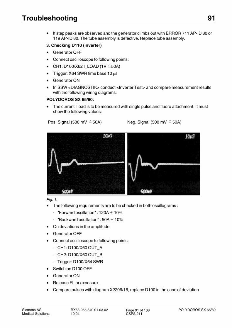
• The current I load is to be measured with single pulse and fluoro attachment. It must show the following values:
Fig. 1:
• The following requirements are to be checked in both oscillograms :
- "Forward oscillation" : 120A ± 10%
- "Backward oscillation” : 50A ± 10%
• On deviations in the amplitude:
• Generator OFF
• Connect oscilloscope to following points:
- CH1: D100/X60 OUT_A
- CH2: D100/X60 OUT_B
- Trigger: D100/X64 SWR
• Switch on D100 OFF
• Generator ON
• Release FL or exposure.
• Compare pulses with diagram X2206/16, replace D100 in the case of deviation
Pos. Signal (500 mV 50A) Neg. Signal (500 mV 50A)
Siemens AG RX63-055.840.01.03.02 POLYDOROS SX 65/8010.04 CSPS 211
Page 91 of 108Medical Solutions
92 Troubleshooting
• If pulses are OK proceed as follows:
- Replace inverter
- The FL attachment must be adjusted anew after replacement of the inverter.
4. Checking D111 "FL attachment”
• Check contacts of the "K6" contactor.
• Check screw connections.
5. Checking D220 filament board
If ERROR messages 711 and 119 AD-IP 80 occur sporadically, and if no error is found when checking D100, D110, D111, D115, D165 and the tube assembly, D220 can be defective. Perform check as follows:
• Ribbon cable between D100 and D220 must be run in front of the retaining bracket on H1.
• Generator OFF
• Connect oscilloscope to following points:
- CH1: MAACT (IRö ACT) D100/X64 MA_ACT
- CH2: kVACT D100/X61 kV-ACT
- Trigger: D100/X64 SWR
• SS switch on D100 OFF
• Generator ON
• Check trigger
• SS switch on D100 ON
• Perform measurements with both focal spots.
• Release exposure with 81 kV,32 mAs,100 ms and observe the tube current. If the cur-rent wave shape is linear, increase tube current with the mAs button and retain the 100 ms. If a too high current is measured in the measurement, the tube must be adjust-ed again. If abrupt changes of push factor occur during the setting and if the current can not be adjusted, replace D220.
6. HCheck high-voltage cable
• Check the plug of the HV cable for tracking. If tracking is present, the HV cable must be replaced.
• If there is no tracking on the HV cable, clean the HV plug, replace corona disks and gas-ket and insert in the tube assembly with silicone oil.
• No corona disks may be used on the transformer side.
• Approx. 10 mm oil must be present in the transformer receptacle.
• The ohmic value of the shielding braid may be 1 Ohm per meter. If there is suspicion the the HV cable is no longer voltage-proof, the HV cable must be replaced.
POLYDOROS SX 65/80 RX63-055.840.01.03.02 Siemens AG10.04 CSPS 211
Page 92 of 108Medical Solutions
Troubleshooting 93
Error 712 0
Meaning:
Plus kVmax error
Description:
The positive side of the high voltage is monitored for an absolute value of 80 kV.
Display LED D100.V168 "KV MAX+"
Possible causes and action:
• Check the +KV actual value on D220.X18.A7 and D100.X61 "KV+" (see Generator Wir-ing Diagram, page 15) at both test points: 1V 10KV.
• FL attachment is out of adjustment. Perform adjustment.
• Check ribbon cable between D220.X1 and D100.X1
• kV controller defective, replace D100
• kV actual value sensing on D220 defective
• Tube assembly or high-voltage cable defective
• High-voltage generator defective
• If the tube assembly is replaced, perform tube adjustment.
Siemens AG RX63-055.840.01.03.02 POLYDOROS SX 65/8010.04 CSPS 211
Page 93 of 108Medical Solutions
94 Troubleshooting
Error 713 0
Meaning:
Minus-kVmax error
Description:
The negative side of the high voltage is monitored for an absolute value of 80 kV.
Display LED D100.V167 "KV MAX-"
Possible causes and action:
• Check the kV actual value on D220.X18.A8 and D100.X61 "kV-" (see Generator Wiring Diagram, page 15) at both test points: 1V -10KV.
• Check ribbon cable between D220.X1 and D100.X1, kV controller defective
• kV actual value sensing on D220 defective
• Tube assembly or high-voltage cable defective
• High-voltage cable defective
• D100, D220 defective, replace.
• If the tube assembly is replaced, perform tube adjustment".
POLYDOROS SX 65/80 RX63-055.840.01.03.02 Siemens AG10.04 CSPS 211
Page 94 of 108Medical Solutions
Troubleshooting 95
Error 714 0
Meaning:
Plus-kVmin error
Description:
The plus kV(min) monitoring becomes active if the +kV actual value is more than 10 kV less than the +kV nominal value.
Display LED D100.V166 "kV MIN+"
Possible causes and action:
• +kV actual value on D220. Check X18.A7 and D100.X61 test point "kV+" (see Genera-tor Wiring Diagram, page 15) at both test points: 1V 10kV
• Check ribbon cable between D220.X1 and D100.X1.
• Perform "Diagnostic/Inverter Test"
• Check the oscillation current on D100.X62 "I_LOAD" (1V = 50A) and compare it with the diagram for ERROR 711.
• Check connection screws in the intermediate circuit and inverter.
• Measure intermediate circuit voltage at D110.X2 and X1 (see wiring diagram X2206-16)
- UZACT = 1.4 x Umains
- Caution! Direct voltage
• Actual value sensing D220 defective
• kV controller defective
• Tube arcing
• High-voltage generator H1 defective
• High-voltage cable OK?
• Filament current too high, perform tube adjust.
• If the tube assembly is replaced, perform tube adjust".
Siemens AG RX63-055.840.01.03.02 POLYDOROS SX 65/8010.04 CSPS 211
Page 95 of 108Medical Solutions
96 Troubleshooting
Error 715 0
Meaning:
Minus-kVmin error
Description:
The minus kVmin monitoring becomes active if the -kV actual value is more than 10 kV less than the -kV nominal value.
Display LED D100.V165 "kV MIN-"
Possible causes and action:
• Check the minus kV actual value on D220.X18.A8 and D100.X61 "kV-" (see Generator Wiring Diagram, page 15) at both test points: 1V -10KV.
• Check ribbon cable between D220.X1 and D100.X1
• Perform "Diagnostic/Inverter Test"
• Check the oscillation current on D100.X62 "I_LOAD" (1V 50A) and compare it with the diagram for ERROR 711.
• Check connection screws in the intermediate circuit and inverter
• Measure intermediate circuit voltage at D110.X2 and X1 (X2206-16)
- UZACT = 1.4 x Umains
- Caution! Direct voltage
• Actual value sensing D220 defective
• kV controller defective
• Tube arcing
• High-voltage generator H1 defective
• High-voltage cable OK?
• Filament current too high, perform tube adjust.
POLYDOROS SX 65/80 RX63-055.840.01.03.02 Siemens AG10.04 CSPS 211
Page 96 of 108Medical Solutions
Troubleshooting 97
Error 716 0
Meaning:
Short circuit in main inverter (one incident)
Description:
During an exposure or a fluoro there are in between 3.6 sec ONE inverter short circuit. This will result in under exposed images or in a DR series in a blank image plus an under-exposed one. If the short circuit continues, error 711 will be caused.
Siemens AG RX63-055.840.01.03.02 POLYDOROS SX 65/8010.04 CSPS 211
Page 97 of 108Medical Solutions
98 Troubleshooting
Error 800 0
Meaning:
Temperature switch of tube has been switched
Description:
Tube is too hot, the temperature switch of tube has been switched.
Possible causes and action:
• Tell the user to wait for next exposure until tube has cooled down a bit.
• With POLYDOROS SX65/80:
- Temperature switch of the tube is only connected for OPTI154/30/50R-100 and MEGALIX tube assemblies, for all other tube assemblies there is a jumper on D160.X61.1 and 2 for AP1, or D160.X62.1 and 2 for AP2, or D160.X63.1 and 2.
POLYDOROS SX 65/80 RX63-055.840.01.03.02 Siemens AG10.04 CSPS 211
Page 98 of 108Medical Solutions
Troubleshooting 99
Error 803 0
Meaning:
Bridge short circuit in the rotating anode starter inverter
Description:
A bridge short circuit has occurred in a branch of the inverter.
The "R_KURZ" signal is indicated by the LED’s V35 on D100 and V114 on D115.
Possible causes and action:
• Check stator resistances at the tube assembly connection (particulars at 20°)
- In the 3-phase stator
- In the 2-phase stator
- In the (Opti 154...)
• Stator defective?
• Correct stator configured?
• Check activation "AN0 - AN5" of the IGBT modules, from the D100 to the D115 (see wir-ing diagram X2206-31).
- POLYDOROS = OFF
- On D100 switch S2 "ZK" = OFF
- POLYDOROS = ON
- Check activation signals "AN0 - AN5" on the D100.X65 with oscilloscope. The indi-vidual voltage pulse of the activation signals "AN0 - AN5" should be approximately 13 V. If the activation signals are smaller than 10 V, the D100 is to be replaced.
• D115 defective
• Check phase shifter "Connection 2 phase tube assembly" connection (see wiring dia-gram X2206-30)
• Test stator cable, disconnect cable at tube assembly and measure with ohmmeter, there must be no connection between the leads I, II, 0.
• Test the currents in the stator leads with a current transformer.
0 - I 2.0 - 2.6 ohms
0 - II 2.0 - 2.6 ohms
0 - I 13 - 16 ohms
0 - II 18 - 20 ohms
0 - I ca. 10 ohms
0 - II ca. 10 ohms
Siemens AG RX63-055.840.01.03.02 POLYDOROS SX 65/8010.04 CSPS 211
Page 99 of 108Medical Solutions
100 Troubleshooting
• Measure intermediate circuit voltage at:
- D115.X6 and X5
- D110.X6 and X5
- UZACT = 1.4 x Umains
- Caution! Direct voltage
• Check intermediate circuit voltage connection terminals D165, D110, D115.
POLYDOROS SX 65/80 RX63-055.840.01.03.02 Siemens AG10.04 CSPS 211
Page 100 of 108Medical Solutions
Troubleshooting 101
Error 804 0
Meaning:
Invalid tube data
Description:
Error when selecting 2-phase or 3-phase tube assembly or error in nominal speed 5 Hz / 6 Hz
Siemens AG RX63-055.840.01.03.02 POLYDOROS SX 65/8010.04 CSPS 211
Page 101 of 108Medical Solutions
102 Troubleshooting
Error 805 0
Meaning:
No current in the main phase, no rotation (no ROT)
Description:
During bootup, the current is measured in the primary phase (test point D100.X60
"I_ANL") 1V 5A. The current must be more than 1.5 A.
The error is displayed no ROT, green LED V36 on D100 not on
Possible causes and action:
• Check activation "AN0 - AN5" of the IGBT modules, from the D100 to the D115 (see wir-ing diagram X2206-31).
- POLYDOROS = OFF
- On D100 switch S2 "ZK" = OFF
- POLYDOROS = ON
- Check activation signals "AN0 - AN5" on the D100.X65 with oscilloscope. The indi-vidual voltage pulse of the activation signals "AN0 - AN5" should be approximately 13 V. If the activation signals are smaller than 10 V, the D100 is to be replaced.
• D115 defective?
• Interruption in the stator cable. Disconnect the cable at the tube assembly and mea-sure ohmically, there must be no connection between the leads I, II, 0.
• Test the currents in the stator leads with a current transformer.
• Measure intermediate circuit voltage at D115.X6 and X5 and on D110.X6 and X5.
- UZACT = 1.4 x Umains
- Caution! Direct voltage
• Check intermediate circuit voltage connection terminals D165, D110, D115.
• Check stator resistances at the tube assembly connection (at 20° C)
- In the 3-phase stator
- In the 2-phase stator
- In the (Opti 154...)
0 - I 2.0 - 2.6 ohms
0 - II 2.0 - 2.6 ohms
0 - I 13 - 16 ohms
0 - II 18 - 20 ohms
0 - I ca. 10 ohms
0 - II ca. 10 ohms
POLYDOROS SX 65/80 RX63-055.840.01.03.02 Siemens AG10.04 CSPS 211
Page 102 of 108Medical Solutions
Troubleshooting 103
Error 806 0
Meaning:
Intermediate circuit is switched off when switching on the generator
Description:
During power-up inspect whether or not the intermediate circuit is switched on. If this is not the case and a liquid bearing X-ray tube is connected to the generator, then this tube will not be accelerated. The system is no longer ready for operation.
Possible causes and action:
• Switch off system, switch on intermediate circuit and switch on system again
Siemens AG RX63-055.840.01.03.02 POLYDOROS SX 65/8010.04 CSPS 211
Page 103 of 108Medical Solutions
104 Troubleshooting
Error 810 0
Meaning:
Stator contactor acknowledgment "SRTRSU" missing
Description:
K3 or K31 / K32 stator breaker (see Wiring Diagram, page 30) has not switched over.
Possible causes and action:
• K3 or K31 / K32 breaker defective.
• Acknowledgment interrupted.
• Check signal on D100.X20.23 "STRSU”.
• Signal OK
• K3 or K31 / K32 ON = 0V
• K3 or K31 / K32 OFF = 24V (± 15%)
• Replace D100
• Check whether a third workstation is configured and order contactor attachment, if nec-essary.
POLYDOROS SX 65/80 RX63-055.840.01.03.02 Siemens AG10.04 CSPS 211
Page 104 of 108Medical Solutions
Troubleshooting 105
Check of “Di Pulses” in XCS Network 0
Measurements in the XCS Cable Network 0
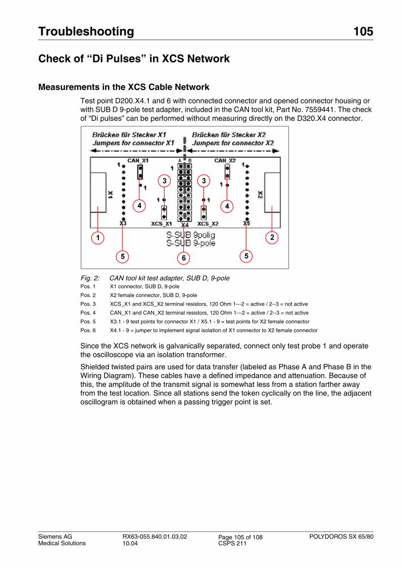
Test point D200.X4.1 and 6 with connected connector and opened connector housing or with SUB D 9-pole test adapter, included in the CAN tool kit, Part No. 7559441. The check of “Di pulses” can be performed without measuring directly on the D320.X4 connector.
Fig. 2: CAN tool kit test adapter, SUB D, 9-polePos. 1 X1 connector, SUB D, 9-pole
Pos. 2 X2 female connector, SUB D, 9-pole
Pos. 3 XCS_X1 and XCS_X2 terminal resistors, 120 Ohm 1---2 = active / 2--3 = not active
Pos. 4 CAN_X1 and CAN_X2 terminal resistors, 120 Ohm 1---2 = active / 2--3 = not active
Pos. 5 X3.1 - 9 test points for connector X1 / X5.1 - 9 = test points for X2 female connector
Pos. 6 X4.1 - 9 = jumper to implement signal isolation of X1 connector to X2 female connector
Since the XCS network is galvanically separated, connect only test probe 1 and operate the oscilloscope via an isolation transformer.
Shielded twisted pairs are used for data transfer (labeled as Phase A and Phase B in the Wiring Diagram). These cables have a defined impedance and attenuation. Because of this, the amplitude of the transmit signal is somewhat less from a station farther away from the test location. Since all stations send the token cyclically on the line, the adjacent oscillogram is obtained when a passing trigger point is set.
Siemens AG RX63-055.840.01.03.02 POLYDOROS SX 65/8010.04 CSPS 211
Page 105 of 108Medical Solutions
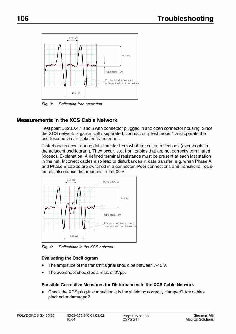
106 Troubleshooting
Fig. 3: Reflection-free operation
Measurements in the XCS Cable Network 0
Test point D320.X4.1 and 6 with connector plugged in and open connector housing. Since the XCS network is galvanically separated, connect only test probe 1 and operate the oscilloscope via an isolation transformer.
Disturbances occur during data transfer from what are called reflections (overshoots in the adjacent oscillogram). They occur, e.g. from cables that are not correctly terminated (closed). Explanation: A defined terminal resistance must be present at each last station in the net. Incorrect cables also lead to disturbances in data transfer, e.g. when Phase A and Phase B cables are switched in a connector. Poor connections and transitional resis-tances also cause disturbances in the XCS.
Fig. 4: Reflections in the XCS network
Evaluating the Oscillogram
• The amplitude of the transmit signal should be between 7-15 V.
• The overshoot should be a max. of 2Vpp.
Possible Corrective Measures for Disturbances in the XCS Cable Network
• Check the XCS plug-in connections; Is the shielding correctly clamped? Are cables pinched or damaged?
400 nS
200 nS
Uss max 2V
Am Netz sind3 Stationen angeschlo
7-15V
Upp max. 2V
Three stations areconnected to the netwo
400 nS
200 nS
Uss max 2V
Am Netz sind
3 Stationen angeschlo
7-15V
‹berschwinger
Upp max. 2V
Three stations areconnected to the netwo
Overshoots
POLYDOROS SX 65/80 RX63-055.840.01.03.02 Siemens AG10.04 CSPS 211
Page 106 of 108Medical Solutions
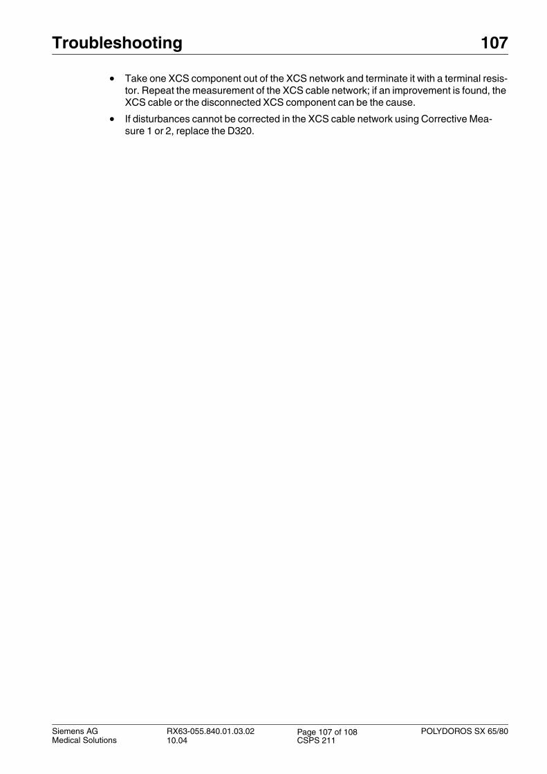
Troubleshooting 107
• Take one XCS component out of the XCS network and terminate it with a terminal resis-tor. Repeat the measurement of the XCS cable network; if an improvement is found, the XCS cable or the disconnected XCS component can be the cause.
• If disturbances cannot be corrected in the XCS cable network using Corrective Mea-sure 1 or 2, replace the D320.
Siemens AG RX63-055.840.01.03.02 POLYDOROS SX 65/8010.04 CSPS 211
Page 107 of 108Medical Solutions
108 Changes to Previous Version
4- 3Changes to Previous Version
Chapter Section Revision
Trouble-shooting
ERROR 810 New K31 / K32 stator breakers added.
Trouble-shooting
Check of “Di Pulses” in XCS Network
Note about the CAN tool kit, Part #7559441 added.
POLYDOROS SX 65/80 RX63-055.840.01.03.02 Siemens AG10.04 CSPS 211
Page 108 of 108Medical Solutions