RO Tablou de comandă pentru motoare Daphne 24V Daphne barriers... · 2015-04-23 · Fabricat doar...
61
1 RO Tablou de comandă pentru motoare Daphne 24V
Transcript of RO Tablou de comandă pentru motoare Daphne 24V Daphne barriers... · 2015-04-23 · Fabricat doar...
1
RO Tablou de comandă pentru motoare Daphne 24V

2
17
RO
Stagnoli D24 este tabloul de comandă conceput pentru Barierele 24V Daphne.
Fabricat doar cu produse de calitate, acesta a fost conceput să aibă consum mic de energie cînd nu este utilizat. O atenţie deosebită a fost acordată profesioniştilor din acest domeniu prin facilitarea programării tabloului de comandă datorită unui afişaj în mai multe limbi (4 limbi).
AVERTISMENTE ŞI NORME DE SECURITATE
• Se recomandă citirea întregului manual de instrucţiuni înainte de instalarea produsului.
• În timpul cablării, energia electrică trebuie oprită.
• Instalarea porţilor automate trebuie efectuată de personal tehnic calificat, iar
normele legale trebuie respectate.
• SECURITATE DUBLĂ: Tabloul de comandă are doi senzori de securitate: un senzor
codificator şi un senzor amperometric.
• Asiguraţi-vă că bariera este solidă, bine fixată cu produse adaptate la
automatizarea Daphne.
Explicaţi utilizatorului final cum funcţionează automatizarea, posibilele pericole legate de aceasta şi nevoia de întreţinere periodică şi nevoia de a verifica dispozitivele de securitate, cel puţin o dată la şase luni.
18
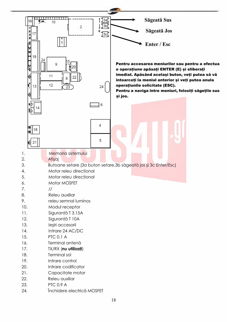
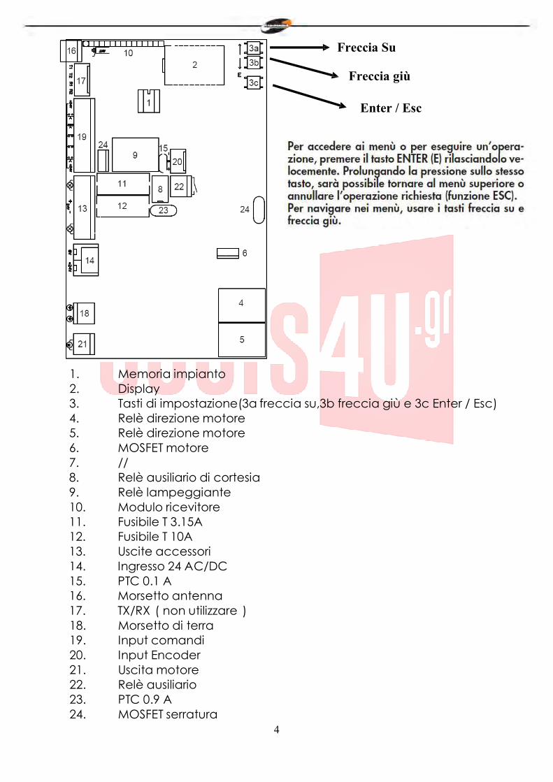
Săgeată Sus
Săgeată Jos
Enter / Esc
Pentru accesarea meniurilor sau pentru a efectua o operațiune apăsați ENTER (E) și eliberați imediat. Apăsând același buton, veți putea să vă întoarceți la meniul anterior și veți putea anula operațiunile solicitate (ESC). Pentru a naviga între meniuri, folosiți săgețile sus și jos.
1. Memoria sistemului 2. Afişaj 3. Butoane setare (3a buton setare,3b săgeată jos şi 3c Enter/Esc) 4. Motor releu direcţional 5. Motor releu direcţional 6. Motor MOSFET 7. // 8. Releu auxiliar 9. releu semnal luminos 10. Modul receptor 11. Siguranţă T 3.15A 12. Siguranţă T 10A 13. Ieşiri accesorii 14. Intrare 24 AC/DC 15. PTC 0.1 A 16. Terminal antenă 17. TX/RX (nu utilizaţi) 18. Terminal sol 19. Intrare control 20. Intrare codificator 21. Capacitate motor 22. Releu auxiliar 23. PTC 0.9 A 24. Închidere electrică MOSFET
19
19
13
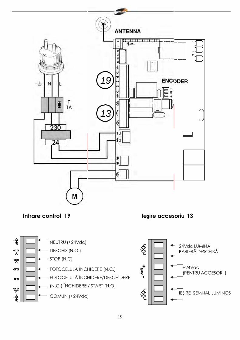
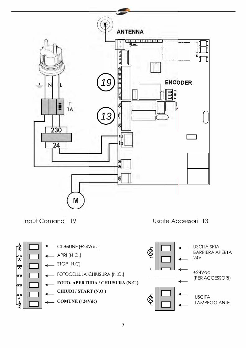
Intrare control 19 Ieşire accesoriu 13
NEUTRU (+24Vdc)
DESCHIS (N.O.)
STOP (N.C)
FOTOCELULĂ ÎNCHIDERE (N.C.)
FOTOCELULĂ ÎNCHIDERE/DESCHIDERE
(N.C ) ÎNCHIDERE / START (N.O)
COMUN (+24Vdc)
24Vdc LUMINĂ BARIERĂ DESCHISĂ
+24Vac (PENTRU ACCESORII)
IEŞIRE SEMNAL LUMINOS
20
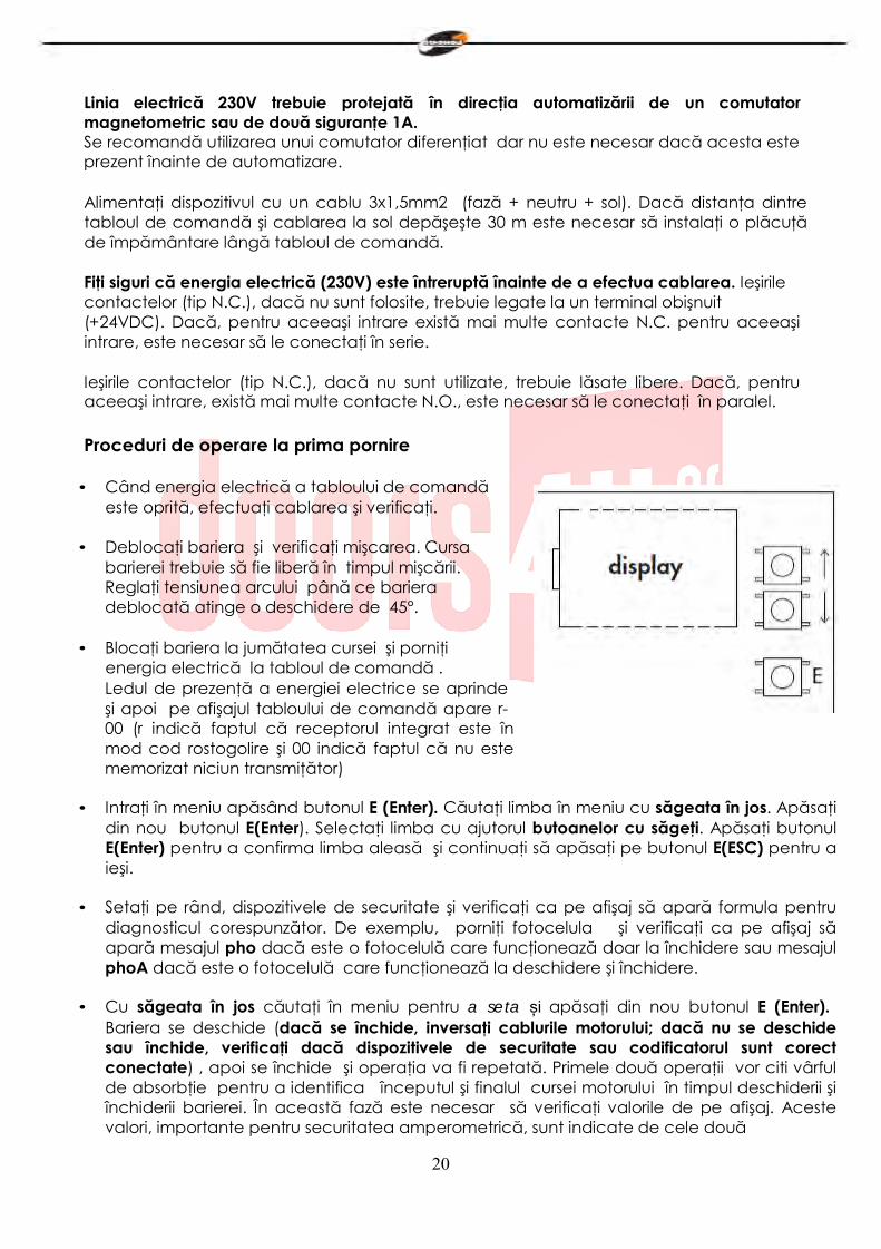
Linia electrică 230V trebuie protejată în direcţia automatizării de un comutator magnetometric sau de două siguranţe 1A. Se recomandă utilizarea unui comutator diferenţiat dar nu este necesar dacă acesta este prezent înainte de automatizare.
Alimentaţi dispozitivul cu un cablu 3x1,5mm2 (fază + neutru + sol). Dacă distanţa dintre tabloul de comandă şi cablarea la sol depăşeşte 30 m este necesar să instalaţi o plăcuţă de împământare lângă tabloul de comandă.
Fiţi siguri că energia electrică (230V) este întreruptă înainte de a efectua cablarea. Ieşirile contactelor (tip N.C.), dacă nu sunt folosite, trebuie legate la un terminal obişnuit (+24VDC). Dacă, pentru aceeaşi intrare există mai multe contacte N.C. pentru aceeaşi intrare, este necesar să le conectaţi în serie.
Ieşirile contactelor (tip N.C.), dacă nu sunt utilizate, trebuie lăsate libere. Dacă, pentru aceeaşi intrare, există mai multe contacte N.O., este necesar să le conectaţi în paralel.
Proceduri de operare la prima pornire
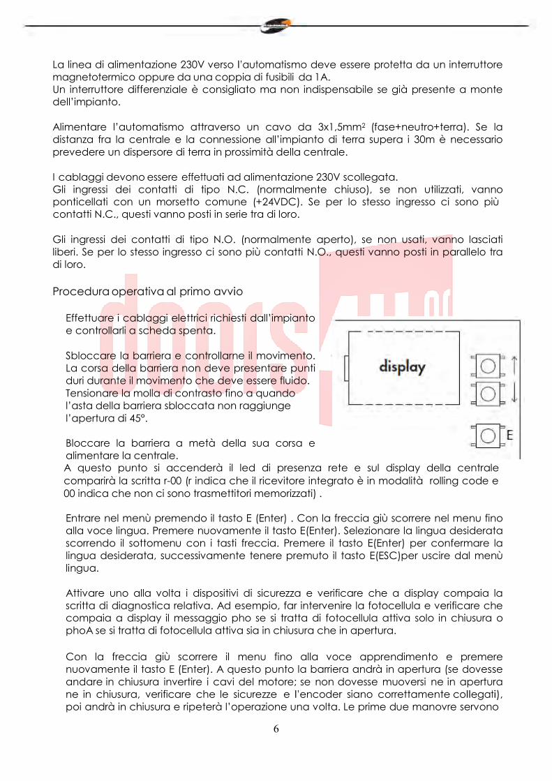
• Când energia electrică a tabloului de comandă
este oprită, efectuaţi cablarea şi verificaţi.
• Deblocaţi bariera şi verificaţi mişcarea. Cursa barierei trebuie să fie liberă în timpul mişcării. Reglaţi tensiunea arcului până ce bariera deblocată atinge o deschidere de 45°.
• Blocaţi bariera la jumătatea cursei şi porniţi
energia electrică la tabloul de comandă . Ledul de prezenţă a energiei electrice se aprinde şi apoi pe afişajul tabloului de comandă apare r- 00 (r indică faptul că receptorul integrat este în mod cod rostogolire şi 00 indică faptul că nu este memorizat niciun transmiţător)
• Intraţi în meniu apăsând butonul E (Enter). Căutaţi limba în meniu cu săgeata în jos. Apăsaţi
din nou butonul E(Enter). Selectaţi limba cu ajutorul butoanelor cu săgeţi. Apăsaţi butonul E(Enter) pentru a confirma limba aleasă şi continuaţi să apăsaţi pe butonul E(ESC) pentru a ieşi.
• Setaţi pe rând, dispozitivele de securitate şi verificaţi ca pe afişaj să apară formula pentru
diagnosticul corespunzător. De exemplu, porniţi fotocelula şi verificaţi ca pe afişaj să apară mesajul pho dacă este o fotocelulă care funcţionează doar la închidere sau mesajul phoA dacă este o fotocelulă care funcţionează la deschidere şi închidere.
• Cu săgeata în jos căutaţi în meniu pentru a seta și apăsaţi din nou butonul E (Enter).
Bariera se deschide (dacă se închide, inversaţi cablurile motorului; dacă nu se deschide sau închide, verificaţi dacă dispozitivele de securitate sau codificatorul sunt corect conectate) , apoi se închide şi operaţia va fi repetată. Primele două operaţii vor citi vârful de absorbţie pentru a identifica începutul şi finalul cursei motorului în timpul deschiderii şi închiderii barierei. În această fază este necesar să verificaţi valorile de pe afişaj. Aceste valori, importante pentru securitatea amperometrică, sunt indicate de cele două
21
numere de pe afişaj cu litera a înainte în timpul fazei de deschidere şi litera c în timpul fazei de închidere. Când faza de setare este terminată, pe afişaj apare ok dacă programarea este corectă sau apare err în cazul unei erori. Apăsaţi timp de două secunde butonul de selecţie E (Esc) pentru a ieşi din programare. Introduceţi corect în meniu nivelurile forţei antilovire la deschidere şi închidere care trebuie să fie mai mari decât valorile maxime afişate în timpul fazei de învăţare. Această reglare poate afecta gradul de securitate al automatizării.
În timpul manevrelor de învăţare, comenzile START, OPEN, CLOSE nu sunt active, iar tabloul de comandă lucrează cu parametrii forţă la maximum. Asiguraţi-vă, chiar dacă dispozitivele de securitate sunt încă active, că nimeni şi nimic nu se află în cursa de lucru a barierei.
• Efectuaţi câteva cicluri de teste verificând buna funcţionare a întregii instalaţii.
• Măsuraţi forţa de impact a barierei referitor la ceea ce este menţionat în norma
EN12445.
22
MENIU
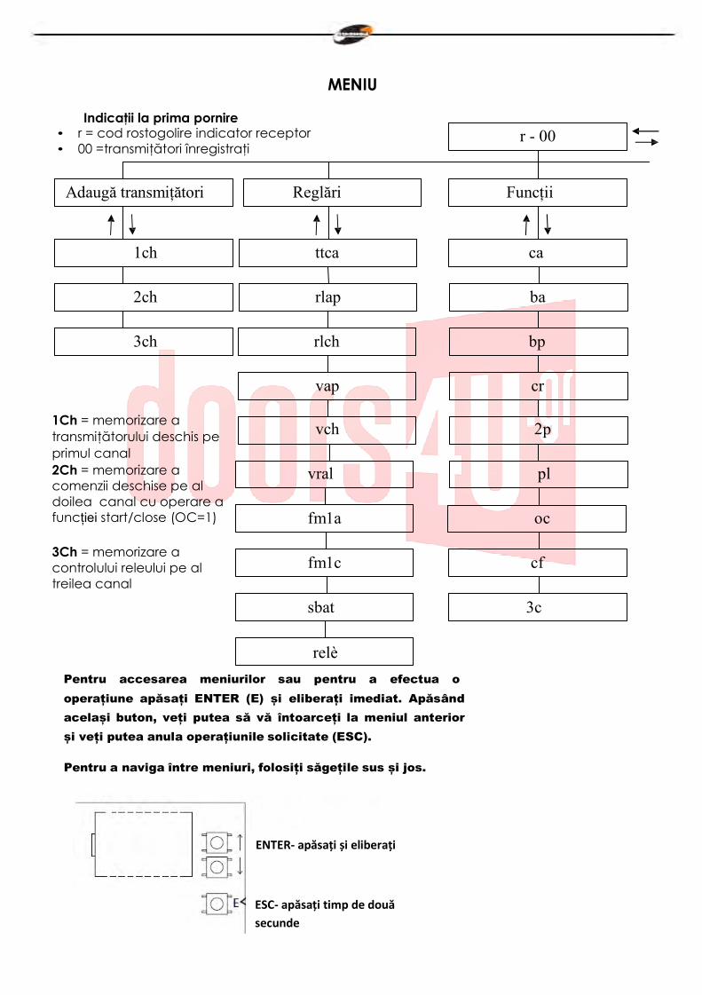
Indicaţii la prima pornire • r = cod rostogolire indicator receptor • 00 =transmiţători înregistraţi
r - 00
Adaugă transmițători Reglări Funcții
1ch ttca ca
2ch rlap ba
3ch rlch bp
vap cr
1Ch = memorizare a transmiţătorului deschis pe primul canal 2Ch = memorizare a comenzii deschise pe al doilea canal cu operare a funcției start/close (OC=1)
3Ch = memorizare a controlului releului pe al treilea canal
vch 2p
vral pl
fm1a oc
fm1c cf
sbat 3c
relè
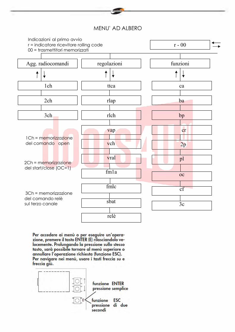
Pentru accesarea meniurilor sau pentru a efectua o operațiune apăsați ENTER (E) și eliberați imediat. Apăsând același buton, veți putea să vă întoarceți la meniul anterior și veți putea anula operațiunile solicitate (ESC).
Pentru a naviga între meniuri, folosiți săgețile sus și jos.
ENTER- apăsați și eliberați
ESC- apăsați timp de două secunde
23
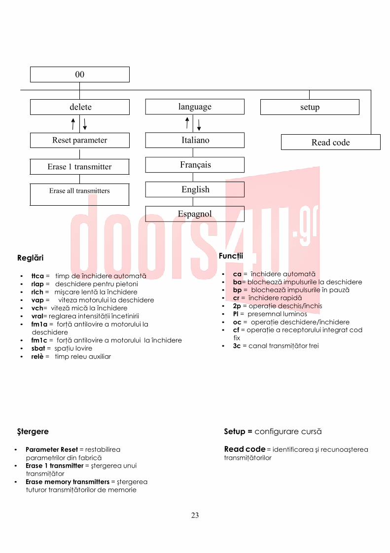
language
Italiano
Français
English
Espagnol
00
delete setup
Reset parameter Read code
Erase 1 transmitter
Erase all transmitters
Reglări
• ttca = timp de închidere automată • rlap = deschidere pentru pietoni • rlch = mişcare lentă la închidere • vap = viteza motorului la deschidere • vch= viteză mică la închidere • vral= reglarea intensităţii încetinirii • fm1a = forţă antilovire a motorului la
deschidere • fm1c = forţă antilovire a motorului la închidere • sbat = spaţiu lovire • relè = timp releu auxiliar
Funcţii • ca = închidere automată • ba= blochează impulsurile la deschidere • bp = blochează impulsurile în pauză • cr = închidere rapidă • 2p = operaţie deschis/închis • Pl = presemnal luminos • oc = operaţie deschidere/închidere • cf = operaţie a receptorului integrat cod
fix • 3c = canal transmiţător trei
Ştergere • Parameter Reset = restabilirea
parametrilor din fabrică • Erase 1 transmitter = ştergerea unui
transmiţător • Erase memory transmitters = ştergerea
tuturor transmiţătorilor de memorie
Setup = configurare cursă Read code = identificarea şi recunoaşterea transmiţătorilor
24
Configuraţia tabloului de comandă
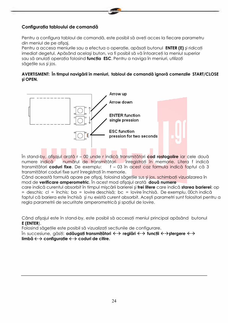
Pentru a configura tabloul de comandă, este posibil să aveţi acces la fiecare parametru din meniul de pe afişaj. Pentru a accesa meniurile sau a efectua o operaţie, apăsaţi butonul ENTER (E) şi ridicaţi imediat degetul. Apăsând acelaşi buton, va fi posibil să vă întoarceţi la meniul superior sau să anulaţi operaţia folosind funcţia ESC. Pentru a naviga în meniuri, utilizaţi săgeţile sus şi jos.
AVERTISMENT: În timpul navigării în meniuri, tabloul de comandă ignoră comenzile START/CLOSE şi OPEN.
În stand-by, afişajul arată r – 00 unde r indică transmiţători cod rostogolire iar cele două numere indică numărul de transmiţători înregistraţi în memorie. Litera f indică transmiţători coduri fixe. De exemplu: f – 03 în acest caz formula indică faptul că 3 transmiţători coduri fixe sunt înregistraţi în memorie. Când această formulă apare pe afişaj, folosind săgeţile sus şi jos, schimbaţi vizualizarea în mod de verificare amperometric. În acest mod afişajul arată două numere care indică curentul absorbit în timpul mişcării barierei şi trei litere care indică starea barierei: op = deschis; cl = închis; ba = lovire deschisă; bc = lovire închisă. De exemplu, 00ch indică faptul că bariera este închisă şi nu există curent absorbit. Aceşti parametri sunt folositori pentru a regla parametrii de securitate amperometrică şi spaţiul de lovire.
Când afişajul este în stand-by, este posibil să accesaţi meniul principal apăsând butonul E (ENTER). Folosind săgeţile este posibil să vizualizaţi secţiunile de configurare. În succesiune, găsiţi: adăugaţi transmiţători reglări funcţii ştergere limbă configuraţie coduri de citire.
25
Adăugaţi transmiţători
Înainte de a memoriza un transmiţător, asiguraţi-vă că este compatibil cu tipul de receptor care este integrat (cu afişajul în stand-by, va apărea r pentru un receptor cod rostogolire sau f pentru un receptor cod fix). Receptorul poate memoriza coduri rostogolire tip HCS300 STAGNOLI cu miliarde de combinaţii sau coduri fixe tip HT53200 cu 13 biţi sau partea fixă a unui cod rostogolire (28 biţi SN). Este posibil să memoreze până la 76 coduri (transmiţători diferiţi ).
• Intraţi în meniu adăugaţi transmiţători apăsând butonul E(ENTER), treceţi peste afişajul
care arată 1ch, 2ch sau 3ch cu săgeţile şi selectaţi canalul care urmează a fi memorat. Apăsaţi butonul E (ENTER) pentru a confirma canalul care va fi memorat. Apoi apăsaţi butonul transmiţătorului care va fi memorat când apare apăsaţi pe afişaj. Pe afişaj va apărea ok dacă operaţia a fost efectuată corect sau err dacă sunt erori de înregistrare sau full dacă memoria receptorului este plină. Dacă nu se întâmplă nimic înseamnă că transmiţătorul nu este compatibil.
• antenă externă instalată departe de sol măreşte vizibilitatea dintre transmiţător şi
receptor. Puterea receptorului poate fi redusă dacă părţi de metal sau beton armat sunt aşezate lângă el.
Reglări
Intraţi în meniul Reglare pentru a regla parametrii. Alegeţi parametrul care va fi reglat utilizând săgeţile şi apăsaţi butonul E(ENTER) pentru a vedea valoarea înregistrată. Utilizaţi săgeţile pentru a modifica parametrul şi confirmaţi apăsând butonul E(ENTER). Apăsaţi butonul E(ESC) timp de aproape 2 secunde pentru a ieşi din meniuri.
• ttca (timp închidere automată): acesta este timpul cuprins între momentul în care
bariera este larg deschisă şi momentul în care este închisă automat. Dacă fotocelula este pornită, timpul ttca se numără de la timpul la care fotocelula este liberă. Timpul de nefuncţionare setat de Stagnoli este de 10 sec şi poate fi reglat de la 1 la 240 sec.
• rlap (cursă încetinită la deschidere): tabloul de comandă încetineşte cursa motorului
în partea de sfârşit a deschiderii sale. Cursa de nefuncţionare setată este 50% şi poate fi reglată de la 0 la 90. Reglaţi această valoare pentru a împiedica bariera să aibă oscilaţii când ajunge la sfârşitul cursei în deschidere.
• rlch (cursă încetinită la închidere): tabloul de comandă încetineşte cursa motorului în
partea de final a închiderii. Cursa de nefuncţionare setată este 50% şi poate fi reglată de la 0 la 90. Reglaţi această valoare pentru a împiedica bariera să aibă oscilaţii când ajunge la finalul cursei în închidere.
• vap (viteza motorului deschidere): setaţi viteza motorului în timpul fazei de deschidere.
Viteza de nefuncţionare setată este 5 şi poate fi reglată de la 1 la 10.
• vch (viteza motorului închidere): setaţi viteza motorului în timpul fazei de închidere.
Viteza de nefuncţionare setată este 5 şi poate fi reglată de la 1 la 10.
• vral = reglarea intensităţii încetinirii) Viteza de nefuncţionare setată este 5 şi poate fi
reglată de la 1 la 10.
26
• fm1a (forţă antilovire la deschidere): aceasta este forţa antilovire a barierei. Valoarea de nefuncţionare setată de Stagnoli este 50 şi poate fi reglată de la 10 la 99.
• fm1c (forţă antilovire la închidere): aceasta este forţa antilovire a barierei. Valoarea
de nefuncţionare setată de Stagnoli este 50 şi poate fi reglată de la 10 la 99.
AVERTIZARE: modul în care aceşti doi parametri sunt setaţi poate influenţa nivelul de siguranţă al sistemului. Stagnoli recomandă setarea acestui parametru cu o marjă de siguranţă care este de cel puţin +10 comparat cu curentul maxim consumat de motor în fazele de deschidere şi respectiv închidere. Poate fi vizualizat în timpul cursei motorului pe afişajul din al doilea ecran principal (control amperometric). fm1a şi fm1c cu valori mici, indică o mai mare sensibilitate antilovire. Valorile prea mari pot detecta un punct tare cum ar fi un obstacol şi prin urmare o absorbţie de curent mai ridicată. La finalul instalării, verificaţi ca forţa impactului să fie în conformitate cu regulamentul EN12453.
• sbat (spaţiu lovire): acesta este procentajul cursei individualizat ca spaţiu lovire. În
zonă, securitatea amperometrică sau a codificatorului va fi detectată drept comutator limită şi nu ca obstacol. Valoarea de nefuncţionare setată de Stagnoli este 10 şi poate fi reglată de la 5 la 20.
• relé (timp releu auxiliar): acesta este timpul în care contactul releului auxiliar rămâne
închis după ce bariera s-a închis. În cazul parametrului activ 3c, această valoare indică în câte secunde contactul releului auxiliar va fi închis după ce s-a apăsat pe al treilea canal transmiţător.
27
Funcţii
Intraţi în meniul funcţii pentru a regla parametrii. Folosind săgeţile alegeţi parametrul care va fi modificat şi apăsaţi pe butonul E(ENTER) pentru a vedea dacă funcţia este activă (1) sau nu (0). Apăsaţi be butoanele cu săgeţi pentru a modifica. Apoi confirmaţi apăsând butonul E (ENTER) şi apăsaţi pe butonul E (ESC) pentru aproape 2 secunde pentru a ieşi.
• ca (închidere automată): închiderea automată a barierei după ce s-a deschis complet. Setaţi ttca pentru a regla timpul care trebuie să se scurgă între finalul deschiderii şi începutul închiderii automate.
• ba (blocarea impulsului în timpul deschiderii): tabloul de comandă ignoră impulsurile
START în timpul fazei de deschidere.
• bp (blocarea impulsurilor în timpul pauzei): tabloul de comandă ignoră impulsurile
START/CLOSE, OPEN în timpul pauzei dintre deschidere şi închiderea automată. Aceste funcţii sunt utile în cazul multor treceri cu multe intrări în aceeaşi intrare.
• cr (închidere rapidă): activează timpul de închidere rapidă automată după trecerea
prin fotocelule în timpul fazei de deschidere sau când bariera este deschisă. Timpul de reglare ttca (dacă este activ şi mai mare decât ch r) este automat redus la ch r secunde.
• 2p (operaţie deschis/închis): dacă este activă, la fiecare impuls START, mişcarea
barierei inversează direcţia (OPENING – CLOSING). Dacă nu este activă, ordinea barierei este OPENING – PAUSE (ttca) – CLOSING – STOP.
• pl (presemnal luminos): după comanda de deschidere a barierei, semnalul luminos se
activează timp de două secunde înainte de începerea fazei de deschidere sau închidere.
• oc (funcţie deschis/închis): intrarea terminalului START devine OPEN. Prin activarea
acestei funcţii, o comandă deschide bariera, iar o altă comandă închide bariera.
• cf (operarea receptorului integrat cu cod fix): dacă este activ, receptorul lucrează
cu coduri fixe.
• 3c (al treilea canal transmiţător): dacă este activ, când se apasă pe al treilea canal,
contactul releului auxiliar se închide în timp, în secunde, configurat în parametrul relé. Verificaţi să aveţi înregistrat în memorie al treilea canal transmiţător).
28
Anulare În acest meniu este posibil să resetaţi setările din fabrică sau să anulaţi controale radio prezente în memorie. Intraţi în meniul anulare, alegeţi parametrul cu butoane săgeţi şi confirmaţi cu butonul E (ENTER). Ieşiţi apăsând butonul E (ESC) timp de aproape 2 secunde.
• Parameter reset: pentru a reseta toate valorile funcţiilor şi reglărilor la setările din
fabrică, mergeţi la parametrul reset şi apăsaţi butonul E(ENTER). Pe afişaj apare mesajul rese, care clipeşte până când decizia de a reseta toţi parametrii este confirmată cu butonul E(ENTER) sau operaţia este anulată cu butonul E( ESC).
• erase 1 transmitter: pentru a anula un cod transmiţător, mergeţi la formula 1
transmitter şi apăsaţi pe butonul (E ENTER). Va apărea mesajul PRESS. Acum apăsaţi tasta transmiţătorului care trebuie anulat. Dacă operaţia a fost efectuată corect, va apărea mesajul OK. Dacă acesta nu a fost pus corect, va apărea mesajul ERR.
• Erase all memory transmitters: pentru a anula toţi transmiţătorii înregistraţi, mergeţi la
formula all memory transmitter şi apăsaţi butonul E (ENTER). Va apărea mesajul prg, care clipeşte până când decizia de a anula toate codurile înregistrate este confirmată apăsând pe E (ENTER) sau operaţia este anulată apăsând aceeaşi tastă E(ESC) pentru mai mult timp.
N.B: Pentru a anula memoria receptorului, este necesar ca anularea să se confirme de două ori (erase memory transmitters şi PRG).
Limbă
Afişajul este disponibil în patru limbi: italiano, français, english, espagnol. Pentru a alege limba de operare apăsaţi butonul E (ENTER) şi mergeţi la lingua menu cu săgeţile, apoi apăsaţi butonul E(ENTER) pentru a intra în meniu. Mergeţi la limba aleasă cu săgeţile şi confirmaţi apăsând din nou butonul E(ENTER). Pentru a ieşi din meniul limbă, apăsaţi două secunde butonul E(ESC).
Învăţare
Această operaţie permite automatizării să stabilească automat începutul şi finalul unei curse identificând cursele mecanice respective. Înainte de a continua cu această operaţie, asiguraţi-vă că bariera a fost instalată corect şi. Aşezaţi bariera la mijlocul cursei. Apăsaţi butonul E (ENTER) pentru a intra în meniu, apoi cu săgeţile mergeţi la learning menu şi apăsaţi butonul E (ENTER). În acest moment bariera se va deschide (în caz de închidere, inversaţi cablurile motorului; dacă bariera nu se închide sau deschide, verificaţi dispozitivele de securitate şi conectările codificatorului), apoi se va închide şi va repeta această operaţie încă o dată. Primele două manevre vor identifica începutul şi sfârşitul cursei motorului. Următoarele două manevre vor detecta vârful de absorbţie al motorului pe timpul deschiderii şi închiderii barierei. În această fază, verificaţi valorile afişate. Aceste valori, importante pentru securitatea amperometrică sunt indicate de litera a letter şi două numere de pe afişaj în timpul deschiderii şi de litera b şi două numere în timpul închiderii. La finalul procedurii de Învăţare, pe ecran va apărea formula ok dacă operaţia a fost efectuată corect sau err dacă sunt erori de înregistrare. Apăsaţi
29
E(ENTER) pentru a ieşi din programare. Introduceţi corect în meniu niveluri forţă antilovire la deschidere şi închidere care trebuie să fie mai mari decât valorile maxime afişate în timpul învăţării. AVERTISMENT: această operaţie poate influenţa gradul de securitate al automatizării. În timpul manevrelor de învăţare, tabloul de comandă va ignora comenzile START, OPEN şi CLOSE şi va lucra cu parametrii de forţă maximă. Chiar dacă siguranţele rămân active, asiguraţi-vă că nu există obiecte sau oameni în zona de operare a barierei. Efectuaţi nişte cicluri de teste verificând funcţionarea corectă a întregii instalaţii. Măsuraţi forţa de impact a barierei referitor la dispoziţiile normei EN12445.
Cod citire
Este posibil să verificaţi dacă un cod a fost deja memorat sau să citiţi codul unui transmiţător nou verificând dacă este compatibil cu tabloul de comandă. Poziţionaţi- vă pe read code, apăsaţi E(ENTER). Când afişajul va arăta mesajul PRESS, apăsaţi tasta transmiţătorului care trebuie verificat.
• primul ecran: Sr01 sau Sf01sau –r01 sau –f01 etc.. Prima literă indică producătorul controlului radio, unde S înseamnă Stagnoli şi - a producător generic. A doua literă indică tipul codului, unde r indică cod rostogolire şi f un cod fix. Ultimele două indică codul tastei care a fost apăsată.
• al doilea ecran : P_00, unde P indică cuvântul “poziţie” iar numărul care urmează (crescător de la 0 la 75) indică poziţia ocupată de transmiţător în me mo r i e . Dacă transmiţătorul nu este găsit în memorie, afişajul va arăta ----.
• al treilea şi al patrulea ecran: arată codul hexazecimal al transmiţătorului.
N.B În timpul afişării cuvântului press , când tasta transmiţătorului este apăsată, dacă nu s- a schimbat nimic pe afişaj, înseamnă că transmiţătorul nu este compatibil cu tabloul de comandă Stagnoli (asiguraţi-vă că receptorul este inserat corect şi că antena este corect montată).
30
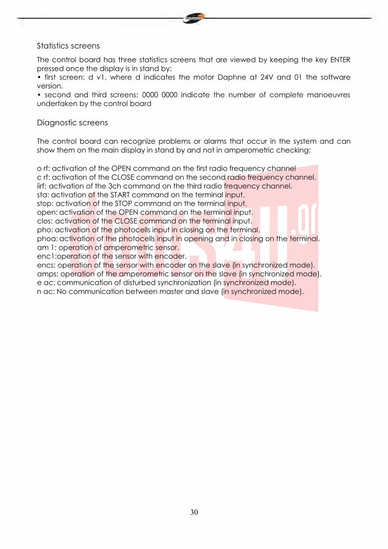
Ecrane statistică
Tabloul de comandă are trei ecrane statistică ce sunt vizualizate păstrând apăsat pe tasta ENTER odată ce afişajul este în stand by: • primul ecran: d v1, unde d indică motorul Daphne la 24V şi 01 versiunea software. • al doilea şi al treilea ecran: 0000 0000 indică numărul de manevre complete efectuate de tabloul de comandă
Ecrane diagnostic
Tabloul de comandă poate recunoaşte probleme sau alarme care au loc în sistem şi le poate arăta pe afişajul principal în stand by şi nu în verificare amperometrică:
o rf: activarea comenzii OPEN pe primul canal de frecvenţă radio c rf: activarea comenzii CLOSE pe al doilea canal de frecvenţă radio. iirf: activarea comenzii 3ch pe al treilea canal de frecvenţă radio. sta: activarea comenzii START la intrarea terminalului. stop: activarea comenzii STOP la intrarea terminalului. open: activarea comenzii OPEN la intrarea terminalului. clos: activarea comenzii CLOSE la intrarea terminalului. pho: activarea intrării fotocelulelor în închidere pe terminal. phoa: activarea intrării fotocelulelor la deschidere şi închidere pe terminal. am 1: operarea senzorului amperometric. enc1:operarea senzorului cu codificator. encs: operarea senzorului cu codificator pe slave (în mod sincronizat). amps: operarea senzorului amperometric pe slave (în mod sincronizat). e ac: comunicarea sincronizării deficiente (în mod sincronizat). n ac: Nicio comunicare între master şi slave (în mod sincronizat).

TA G N
. OL /
X61AI633 Rev.S-11-13
S ...,......, ...,..,_,I'
StagnoliT .G. sri Vla Mantova,travJ, 1OSA/8
+39.0309139511 +39.0309139580 [email protected]
3
I
D24 di Stagnoli è la centrale di comando studiata per le barriere Daphne a 24V.
Realizzata solo con materiali di prima scelta, è stata progettata per avere bassi assorbimenti a riposo permettendo un basso consumo di energia elettrica. Particolare attenzione è stata rivolta ai professionisti del settore facilitando la programmazione della centrale grazie a un display multilingua (4lingue).
AVVERTENZE E NORME DI SICUREZZA
Il presente manuale è stato realizzato da Stagnoli per lo specifico utilizzo da parte di personale professionista e qualificato .
Si consiglia di leggere interamente il manuale di istruzioni prima di procedere all’installazione del prodotto.
Durante la cablatura non deve esserci la presenza di tensione sull’impianto.
Gli impianti di cancelli automatici devono essere installati da personale tecnico qualificato e nel rispetto delle norme di legge.
DOPPIA SICUREZZA: La centrale è dotata di due sensori di sicurezza: uno ad encoder e l’altro amperometrico.
Verificare che la barriera sia solida, ben fissata con fissaggi adatti all’automazione Daphne.
Informare accuratamente l’utilizzatore finale sulla modalità d’uso, sulla pericolosità residua, sulla necessità della manutenzione e sulla necessità di un controllo dei dispositivi di sicurezza, almeno ogni sei mesi.
4
Freccia Su
Freccia giù
Enter / Esc
1. Memoria impianto 2. Display 3. Tasti di impostazione(3a freccia su,3b freccia giù e 3c Enter / Esc) 4. Relè direzione motore 5. Relè direzione motore 6. MOSFET motore 7. // 8. Relè ausiliario di cortesia 9. Relè lampeggiante 10. Modulo ricevitore 11. Fusibile T 3.15A 12. Fusibile T 10A 13. Uscite accessori 14. Ingresso 24 AC/DC 15. PTC 0.1 A 16. Morsetto antenna 17. TX/RX ( non utilizzare ) 18. Morsetto di terra 19. Input comandi 20. Input Encoder 21. Uscita motore 22. Relè ausiliario 23. PTC 0.9 A 24. MOSFET serratura
5
R
19
13
Input Comandi 19 Uscite Accessori 13
COMUNE (+24Vdc)
APRI (N.O.)
STOP (N.C)
FOTOCELLULA CHIUSURA (N.C.)
FOTO. APERTURA / CHIUSURA (N.C )
USCITA SPIA BARRIERA APERTA 24V +24Vac (PER ACCESSORI)
CHIUDI / STA
T (N.O )
USCITA
COMUNE (+24Vdc) LAMPEGGIANTE
6
La linea di alimentazione 230V verso l’automatismo deve essere protetta da un interruttore magnetotermico oppure da una coppia di fusibili da 1A. Un interruttore differenziale è consigliato ma non indispensabile se già presente a monte dell’impianto.
Alimentare l’automatismo attraverso un cavo da 3x1,5mm2 (fase+neutro+terra). Se la distanza fra la centrale e la connessione all’impianto di terra supera i 30m è necessario prevedere un dispersore di terra in prossimità della centrale.
I cablaggi devono essere effettuati ad alimentazione 230V scollegata. Gli ingressi dei contatti di tipo N.C. (normalmente chiuso), se non utilizzati, vanno ponticellati con un morsetto comune (+24VDC). Se per lo stesso ingresso ci sono più contatti N.C., questi vanno posti in serie tra di loro.
Gli ingressi dei contatti di tipo N.O. (normalmente aperto), se non usati, vanno lasciati liberi. Se per lo stesso ingresso ci sono più contatti N.O., questi vanno posti in parallelo tra di loro.
Procedura operativa al primo avvio
Effettuare i cablaggi elettrici richiesti dall’impianto e controllarli a scheda spenta.
Sbloccare la barriera e controllarne il movimento. La corsa della barriera non deve presentare punti duri durante il movimento che deve essere fluido. Tensionare la molla di contrasto fino a quando l’asta della barriera sbloccata non raggiunge l’apertura di 45°.
Bloccare la barriera a metà della sua corsa e alimentare la centrale. A questo punto si accenderà il led di presenza rete e sul display della centrale comparirà la scritta r-00 (r indica che il ricevitore integrato è in modalità rolling code e 00 indica che non ci sono trasmettitori memorizzati) .
Entrare nel menù premendo il tasto E (Enter) . Con la freccia giù scorrere nel menu fino alla voce lingua. Premere nuovamente il tasto E(Enter). Selezionare la lingua desiderata scorrendo il sottomenu con i tasti freccia. Premere il tasto E(Enter) per confermare la lingua desiderata, successivamente tenere premuto il tasto E(ESC)per uscire dal menù lingua.
Attivare uno alla volta i dispositivi di sicurezza e verificare che a display compaia la scritta di diagnostica relativa. Ad esempio, far intervenire la fotocellula e verificare che compaia a display il messaggio pho se si tratta di fotocellula attiva solo in chiusura o phoA se si tratta di fotocellula attiva sia in chiusura che in apertura.
Con la freccia giù scorrere il menu fino alla voce apprendimento e premere nuovamente il tasto E (Enter). A questo punto la barriera andrà in apertura (se dovesse andare in chiusura invertire i cavi del motore; se non dovesse muoversi ne in apertura ne in chiusura, verificare che le sicurezze e l’encoder siano correttamente collegati), poi andrà in chiusura e ripeterà l’operazione una volta. Le prime due manovre servono
7
per identificare l’inizio e la fine della corsa del motore, le due seguenti servono a rilevare il picco di assorbimento del motore durante l’apertura e la chiusura della barriera. In questa fase è necessario monitorare i valori visualizzati a display. Questi valori, importanti per la sicurezza amperometrica, sono indicati dalle due cifre del display precedute dalla lettera a durante la fase di apertura, dalla lettera c durante la fase di chiusura. Al termine della fase di apprendimento, sul display sarà visualizzato ok nel caso di corretta programmazione o err nel caso vi siano stati degli errori. Per uscire dalla programmazione premere per due secondi il tasto di selezione E(Esc). Impostare correttamente i livelli di forza antischiacciamento in apertura e in chiusura nel menu, che devono essere superiori ai valori massimi visualizzati durante l’apprendimento. Questa regolazione può influire sul grado di sicurezza dell’automazione.
Durante le manovre di apprendimento, la centrale ignora i comandi di START, OPEN, CLOSE e lavora con i parametri di forza al massimo. Anche se rimangono attive le sicurezze, assicurarsi che non vi siano oggetti o persone sulla traiettoria di lavoro della barriera.
Effettuare alcuni cicli di prova verificando il corretto funzionamento di tutto l’impianto.
Effettuare le misure della forza di impatto della barriera secondo quanto specificato dalle norme EN12445
8
8
MENU’ AD ALBERO
Indicazioni al primo avvio r = indicatore ricevitore rolling code 00 = trasmettitori memorizzati
r - 00
Agg. radiocomandi regolazioni funzioni
1ch ttca ca
2ch rlap ba
3ch rlch bp
1Ch = memorizzazione del comando open
2Ch = memorizzazione del start/close (OC=1)
3Ch = memorizzazione del comando relè sul terzo canale
vap cr
vch 2p
vral pl
fm1a oc fmlc cf sbat 3c
relè

9
00
cancella lingua apprendimento
reset parametri italiano leggi codice
Cancella 1 radiocomando francese
Cancella tutta la memoria radio
inglese spagnolo
Regolazioni
ttca = tempo di chiusura automatica rlap = corsa rallentata in apertura rlch = corsa rallentata in chiusura vap = velocità motore apertura vch= velocità motore chiusura vral= regolazione velocità e intensità del rallentamento durante la chiusura.ù fm1a = forza antischiacciamento del motore in apertura fm1c = forza antischiacciamento del motore in chiusura sbat = spazio di battuta relé = tempo relé ausiliario
Funzioni
ca = chiusura automatica ba = blocca impulsi durante l’apertura bp= blocca impulsi durante la pausa cr = chiusura rapida 2p = funzionamento apri / chiudi Pl = prelampeggio oc = funzionamento open /close cf = funzionamento del ricevitore integrato a codice fisso 3c = terzo canale radiocomando
Cancella Reset parametri = ripristino dei parametri di fabbrica Cancella 1 radiocomando = cancellazione di un trasmettitore Cancella tutta la memoria radio = cancellazione di tutti i trasmettitori memorizzati
Apprendimento = apprendimento della corsa Leggi codice = identificazione e riconoscimento trasmettitori
10
Configurazione della centrale
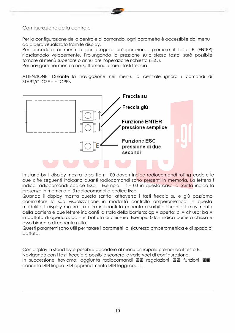
Per la configurazione della centrale di comando, ogni parametro è accessibile dal menu ad albero visualizzato tramite display. Per accedere ai menù o per eseguire un’operazione, premere il tasto E (ENTER) rilasciandolo velocemente. Prolungando la pressione sullo stesso tasto, sarà possibile tornare al menù superiore o annullare l’operazione richiesta (ESC). Per navigare nei menu o nei sottomenu, usare i tasti freccia.
ATTENZIONE: Durante la navigazione nei menu, la centrale ignora i comandi di START/CLOSE e di OPEN.
In stand-by il display mostra la scritta r – 00 dove r indica radiocomandi rolling code e le due cifre seguenti indicano quanti radiocomandi sono presenti in memoria. La lettera f indica radiocomandi codice fisso. Esempio: f – 03 in questo caso la scritta indica la presenza in memoria di 3 radiocomandi a codice fisso. Quando il display mostra questa scritta, attraverso i tasti freccia su e giù possiamo commutare la sua visualizzazione in modalità controllo amperometrico. In questa modalità il display mostra tre cifre indicanti la corrente assorbita durante il movimento della barriera e due lettere indicanti lo stato della barriera: op = aperto; cl = chiuso; ba = in battuta di apertura; bc = in battuta di chiusura. Esempio 00ch indica barriera chiusa e assorbimento di corrente nullo. Questi parametri sono utili per tarare i parametri di sicurezza amperometrica e di spazio di battuta.
Con display in stand-by è possibile accedere al menu principale premendo il testo E. Navigando con i tasti freccia è possibile scorrere le varie voci di configurazione. In successione troviamo: aggiunta radiocomandi regolazioni funzioni cancella lingua apprendimento leggi codici.
11
Aggiunta radiocomandi
Prima di memorizzare un trasmettitore, assicurarsi che sia compatibile con la tipologia di ricevitore integrato (con display a riposo apparirà r, se si tratta di un ricevitore in modalità rolling code o f se si tratta di un ricevitore in modalità codice fisso). Il ricevitore può memorizzare codici rolling code di tipo HCS300 STAGNOLI con miliardi di combinazioni o codici fissi di tipo HT53200 a 13 bit o la parte fissa di un codice rolling code (28 bit SN). É possibile memorizzare fino a 76 codici (trasmettitori diversi).
Entrare nel sottomenu aggiunta radiocomando premendo il tasto E(ENTER), scegliere il canale che si vuole memorizzare portandosi sulla scritta a display 1ch o 2ch o 3ch tramite i tasti freccia. Premere il tasto E(ENTER) per confermare il canale da memorizzare. Successivamente premere il tasto del radiocomando che si desidera memorizzare quando viene visualizzata la scritta premi: a questo punto il display visualizzerà la scritta ok se l’operazione viene portata a termine in maniera corretta, err nel caso si verifichino errori di registrazione o full se la memoria del ricevitore è piena. Se non accadrà nulla significa che il telecomando utilizzato non rientra nello standard adottato da Stagnoli.
Installando un’antenna esternamente alla centrale e lontana dal suolo, l’area di visibilità tra trasmettitori e centrale aumenta. Ricordarsi, inoltre, che parti metalliche e cemento armato, se posti tra la centrale e il ricevitore, diminuiscono la capacità di ricezione di questo ultimo.
Regolazioni
Le regolazioni dei parametri si effettuano entrando nel sottomenu regolazioni. Scegliere il parametro da modificare tramite i tasti freccia e premere E(ENTER) per visualizzare il valore impostato. Utilizzare i tasti freccia per modificare il parametro e confermare tramite il tasto E(ENTER). Per uscire dai menù tenete premuto il tasto E(ESC) per circa 2 secondi.
ttca (tempo di chiusura automatica): è il tempo che intercorre tra l’apertura completa della barriera e la sua chiusura che avviene in modo automatico. Se la fotocellula è occupata, il tempo di ttca viene conteggiato dal momento in cui la fotocellula si disimpegna. Il tempo impostato di default è 10sec ed è regolabile da 1 a 240sec.
rlap (corsa rallentata in apertura): la centrale rallenta la corsa del motore nella parte finale della sua fase di apertura. Il rallentamento impostato di default è il 50% della corsa ed è regolabile da 0 a 90. Impostare questo valore affinché la barriera non presenti forti oscillazioni nell’arrivare a fine corsa in apertura.
rlch (corsa rallentata in chiusura): la centrale rallenta la corsa del motore nella parte finale della sua fase di chiusura. Il rallentamento impostato di default è il 50% della corsa ed è regolabile da 0 a 90. Impostare questo valore affinché la barriera non presenti forti oscillazioni nell’arrivare a fine corsa in chiusura.
vap (velocità motore apertura): impostare la velocità del motore durante la sua fase di apertura. La velocità impostata di default è 5 ed è regolabile da 1 a 10.
Vch (velocità motore chiusura):: impostare la velocità del motore durante la sua fase di chiusura. La velocità impostata di default è 5 ed è regolabile da 1 a 10.
12
vral (velocità di rallentamento durante la chiusura ): impostare la velocità del motore durante la fase di rallentamento in chiusura. La velocità impostata di default è 5 ed è regolabile da 1 a 10.
fm1a (forza antischiacciamento del motore in apertura): è la forza antischiacciamento della barriera. La forza impostata di default è 50 e può essere regolata da 10 a 99.
fm1c (forza antischiacciamento del motore in chiusura): è la forza antischiacciamento della barriera. La forza impostata di default è 50 e può essere regolata da 10 a 99.
ATTENZIONE: l’impostazione di questi due parametri può influire sul grado di sicurezza dell’impianto stesso. Si consiglia di impostare questi parametri con un margine di sicurezza tale che risultino almeno +10 rispetto al massimo della corrente consumata dal motore rispettivamente in fase di apertura e di chiusura. La corrente assorbita durante la corsa del motore si può leggere sul display nella seconda schermata principale (controllo amperometrico). fm1a e fm1c bassi di valore, indicano una maggiore sensibilità antischiacciamento. Valori troppo bassi potrebbero rilevare come ostacolo un punto duro di movimentazione e quindi di assorbimento di corrente più elevato. Verificare al termine dell’installazione che le forze di impatto rispettino la norma EN12453.
sbat (spazio di battuta): è la percentuale della corsa individuata come spazio di battuta. In questa zona la sicurezza encoder o amperometrica verrà rilevata come fine corsa e non come ostacolo. Il valore impostato di default è 10 e può essere regolato da 5 a 20.
relè (tempo relé ausiliario): è il tempo durante il quale il contatto del relé ausiliario rimane chiuso dopo che la barriera si è chiusa. In caso di parametro 3c attivo questo valore indica quanti secondi rimarrà chiuso il contatto relé ausiliario dopo che si è premuto il terzo canale del radiocomando.
Funzioni
Le regolazioni dei parametri si effettuano entrando nel sottomenu funzioni. Scegliere il parametro da modificare tramite i tasti freccia e premere E(ENTER) per visualizzare se la funzione è attivata (1) o se disattivata (0).Per modificare lo stato premere i tasti freccia. Successivamente confermare tramite il tasto E(ENTER) e uscire tenendo premuto il tasto E(ESC) per circa 2 secondi.
ca (chiusura automatica): chiusura automatica della barriera dopo la sua completa apertura. Impostare la regolazione ttca per personalizzare il tempo che deve intercorrere tra la fine dell’apertura e l’inizio della chiusura automatica.
13
ba (blocco impulsi durante l’apertura): la centrale ignora gli impulsi di START durante la fase di apertura.
bp (blocco impulsi durante la pausa): la centrale ignora gli impulsi di START/CLOSE, OPEN durante la pausa tra l’apertura e la chiusura automatica. Queste funzioni si rivelano utili nei casi in cui vi siano diversi passaggi con diversi input attraverso lo stesso ingresso.
cr (chiusura rapida): attiva il tempo di chiusura rapida automatica dopo il passaggio attraverso le fotocellule durante la fase di apertura o a barriera aperta. Il tempo della regolazione ttca (se attivato e superiore di ch r) viene automaticamente ridotto al tempo ch r impostato.
2p (funzionamento apri/chiudi): se attivo, ad ogni impulso di START, il movimento della barriera inverte la direzione (APERTURA - CHIUSURA). Se disattivo la sequenza di movimento della barriera diventa APERTURA - FERMATA (ttca) - CHIUSURA - STOP.
pl (prelampeggio): dopo il comando di apertura della barriera, il lampeggiante o la luce di cortesia si attivano per due secondi prima che venga iniziata la fase di apertura o di chiusura.
oc (funzionamento open/close): l’ingresso in morsettiera di START diventa CLOSE. In questa modalità un comando apre la barriera e l’altro lo chiude.
cf (funzionamento della ricevente integrata a codice fisso): se attivo la ricevente funziona con i codici fissi.
3c (terzo canale radiocomando): se attivo, alla pressione del terzo canale del radiocomando, il contatto del relé ausiliario si chiude per il tempo impostato nel parametro relé. (ricordarsi di aver memorizzato il terzo canale radio).
14
Cancella
In questo sottomenu è possibile ripristinare i parametri di fabbrica o cancellare i radiocomandi presenti in memoria. Entrando nel sottomenu cancella scegliere la voce desiderata tramite i tasti freccia e confermare con il tasto E(ENTER). Uscire tenendo premuto il tasto E(ESC) per circa 2 secondi.
reset parametri: per reimpostare tutti i valori delle regolazioni e delle funzioni a quelli di fabbrica premere il tasto E(ENTER) e portarsi sulla dicitura reset parametri del sottomenu e premere il tasto E(ENTER). Verrà visualizzato il messaggio rese che lampeggerà fino a quando non sarà confermata l’intenzione di reimpostare tutti i parametri tramite tasto E(ENTER) o di annullare l’operazione tramite tasto E(ESC).
cancella 1 radiocomando: per cancellare il codice di un trasmettitore, portarsi sulla dicitura 1 radiocomando del sottomenu e premere il tasto E(ENTER). Verrà visualizzato il messaggio premi. Premere a questo punto il tasto del trasmettitore da cancellare. Se l’operazione sarà portata a termine in maniera corretta, verrà visualizzato il messaggio ok. In caso contrario, err.
cancella tutta memoria radio: per cancellare tutti i trasmettitori registrati, portarsi sulla dicitura tutta memoria radio del sottomenu e premere il tasto E(ENTER). Verrà visualizzato il messaggio prg che lampeggerà fino a quando non sarà confermata l’intenzione di cancellare tutti i codici registrati premendo il tasto E(ENTER) o di annullare l’operazione premendo il tasto E(ESC). N.B: Per portare a termine la cancellazione della memoria radio viene richiesto di confermare due volte la volontà di effettuare la cancellazione stessa (cancella tutta memoria radio e prg).
Lingua
Il display può visualizzare i messaggi in più lingue: italiano, francese, inglese e spagnolo. Per scegliere la lingua di funzionamento premere il tasto E(ENTER) e portarsi sul sottomenu lingua attraverso i tasti freccia e premere E(ENTER) per entrare nel menù .Portarsi sulla lingua desiderata tramite i tasti freccia e confermare premendo nuovamente E(ENTER). Per uscire dal menù lingua premere per due secondi il tasto E(ESC).
15
Apprendimento
Questa operazione permette all’automazione di stabilire automaticamente l’inizio e la fine della corsa. Prima di procedere con questa operazione, assicurarsi che la barriera sia solidamente installata. Posizionare la barriera a metà corsa. Premere il tasto E(ENTER) per entrare nel menù e spostarsi con i tasti freccia fino ad arrivare al sottomenu apprendimento e premere il tasto E(ENTER). A questo punto la barriera andrà in apertura (se dovesse andare in chiusura invertire i cavi del motore; se non dovesse muoversi ne in apertura ne in chiusura, verificare che le sicurezze e l’encoder siano correttamente collegate), poi andrà in chiusura e ripeterà l’operazione un’altra volta. Le prime due manovre servono per identificare l’inizio e la fine della corsa del motore. Le due seguenti, servono a rilevare il picco di assorbimento del motore durante l’apertura e la chiusura della barriera. In questa fase, monitorare i valori visualizzati a display. Questi valori, importanti per la sicurezza amperometrica, sono indicati dalle due cifre del display precedute dalla lettera a durante la fase di apertura, dalla lettera c durante la fase di chiusura. Al termine della fase di apprendimento, sul display sarà visualizzato ok nel caso di corretta programmazione, o err nel caso vi siano stati degli errori. Per uscire dalla programmazione premere il tasto di selezione E(ENTER). Impostare correttamente i livelli di forza antischiacciamento in apertura e in chiusura nel menu, che devono essere superiori ai valori massimi visualizzati durante l’apprendimento ATTENZIONE: questa regolazione può influire sul grado di sicurezza dell’automazione. Durante le manovre di apprendimento, la centrale ignora i comandi di START, OPEN, CLOSE e lavora con i parametri di forza al massimo. Anche se rimangono attive le sicurezze, assicurarsi che non vi siano oggetti o persone sulla traiettoria di lavoro della barriera. Effettuare alcuni cicli di prova verificando il corretto funzionamento di tutto l’impianto. Effettuare le misure della forza di impatto della barriera secondo quanto specificato dalle norme EN12445.
Leggi codice
È possibile verificare se un radiocomando è già stato memorizzato oppure leggere il codice di un nuovo telecomando verificando così la compatibilità con la centrale. Per effettuare tale operazione entrare nel sottomenu leggi codice tramite il tasto E(ENTER). Quando sul display verrà visualizzato il messaggio premi, premere il tasto del trasmettitore che si desidera verificare.
• prima schermata: Sr01 oppure Sf01oppure –r01 oppure –f01 ecc.. Il primo carattere indica il produttore del radiocomando, dove S indica Stagnoli mentre - un produttore generico. Il secondo carattere indica la tipologia di codice, dove r indica rolling code mentre f indica codice fisso. Gli ultimi due caratteri indicano il canale del tasto premuto. • seconda schermata: P_00, dove P indica la parola “posizione” mentre la cifra successiva (progressiva da 0 a 75) indica la posizione occupata dal trasmettitore in memoria. Se il trasmettitore non dovesse essere presente in memoria, apparirà sul display - ---.
16
• terza e quarta schermata: verrà visualizzata la codifica esadecimale del trasmettitore. N.B Durante la comparsa della scritta premi , se alla pressione del tasto del radiocomando non cambia nulla, significa che il radiocomando utilizzato non è compatibile con la centrale Stagnoli (assicurarsi prima che il modulo ricevente sia inserito bene nello zoccolo e che sia montata correttamente l’antenna).
Schermate di statistica
La centrale di comando dispone di tre schermate statistiche che vengono visualizzate mantenendo la pressione del tasto ENTER mentre il display si trova a riposo: • prima schermata: d v1, dove d indica il motore Daphne a 24V e 01 la versione del software. • seconda e terza schermata: 0000 0000 indicano il numero delle manovre complete effettuate dalla centrale fino a quel momento.
Schermate di diagnostica
La centrale è in grado di riconoscere i problemi o gli allarmi che si stanno verificando sull’impianto e di segnalarli sul display principale mentre è a riposo e non in controllo amperometrico:
o rf: attivazione del comando OPEN sul primo canale di radiofrequenza. c rf: attivazione del comando CLOSE sul secondo canale di radiofrequenza. iirf: attivazione del comando 3ch sul terzo canale di radiofrequenza. sta: attivazione del comando di START sull’ingresso della morsettiera. stop: attivazione del comando di STOP sull’ingresso della morsettiera. open: attivazione del comando di OPEN sull’ingresso della morsettiera. clos: attivazione del comando di CLOSE sull’ingresso della morsettiera. pho: attivazione del l’ingresso delle fotocellule in chiusura sulla morsettiera. phoa: attivazione dell’ingresso delle fotocellule in apertura e in chiusura sulla morsettiera. am 1: intervento del sensore amperometrico. enc1: intervento del sensore ad encoder. encs: intervento del sensore ad encoder sullo slave (in modalità sincronizzata). amps: intervento del sensore amperometrico sullo slave (in modalità sincronizzata). e ac: comunicazione di sincronizzazione disturbata (in modalità sincronizzata). n ac: comunicazione tra master e slave assente (in modalità sincronizzata).
17
GB
Stagnoli D24 is the control board designed for the 24V Daphne Barriers.
Manufactured only with first choice products, it has been designed to have low power consumption when not in use. A particular attention has been paid to professional people of this sector making easier the control board programmation thanks to a multilingual display (4 languages).
WARNINGS AND SECURITY NORMS
This manual has been written by Stagnoli for a specific use of professional and qualified people.
It is recommended to read the entire instruction manual before installing the product.
During the wiring, electrical power must be turned off.
Automatic gate installations must be done by qualified technical staff and law norms must be respected.
DOUBLE SECURITY : The control board has two security sensors : an encoder sensor and an amperometric sensor.
Make sure that the barrier is solid, well fixed with fixings adapted to the Daphne automation.
Explain the final user how the automatism works, about possible hazards related to it and the need for periodical maintenance and the need to check security devices, at least every six months.
18
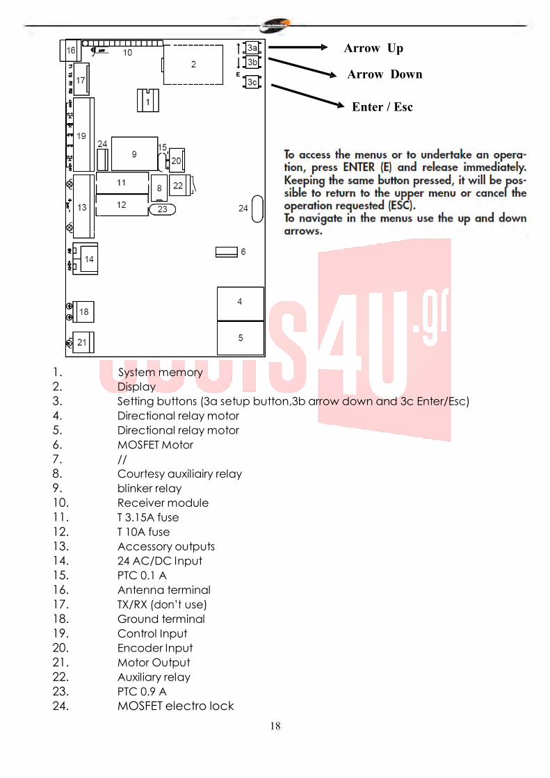
Arrow Up
Arrow Down
Enter / Esc
1. System memory 2. Display 3. Setting buttons (3a setup button,3b arrow down and 3c Enter/Esc) 4. Directional relay motor 5. Directional relay motor 6. MOSFET Motor 7. // 8. Courtesy auxiliairy relay 9. blinker relay 10. Receiver module 11. T 3.15A fuse 12. T 10A fuse 13. Accessory outputs 14. 24 AC/DC Input 15. PTC 0.1 A 16. Antenna terminal 17. TX/RX (don’t use) 18. Ground terminal 19. Control Input 20. Encoder Input 21. Motor Output 22. Auxiliary relay 23. PTC 0.9 A 24. MOSFET electro lock

19
19
13
Control Input 19 Accessory Output 13
COMMON (+24Vdc)
OPEN (N.O.)
STOP (N.C)
CLOSING PHOTOCELL (N.C.)
CLOSING/OPENING PHOTOCELL(N.C )
CLOSING / START (N.O)
COMMON (+24Vdc)
24Vdc OPEN BARRIER LIGHT
+24Vac (FOR ACCESSORIES)
FLASHER OUTPUT
20
The 230V power line must be protected in direction of the automation by a magnetometric switch or by a couple of 1A fuses. It is recommended to use a differential switch but it is not necessary if already present prior to the automation.
Feed the device with a 3x1,5mm2 cable (phase + neutral + ground). If the distance between the control board and the ground wiring exceeds 30 m it is necessary to install an earth plate near the control board.
Make sure that the power (230V) is switched off before carring out cabling. Outputs of contacts (N.C. type), if not used, must be bridged with an ordinary terminal (+24VDC). If, for the same input there are more N.C. contacts for the same input, it is necessary to connect them in series.
Outputs of contacts (N.C. type), if not used, must be left free. If, for the same input, there are more N.O. contacts, it is necessary to connect them in parallel.
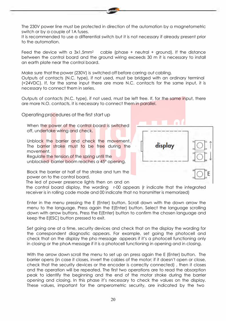
Operating procedures at the first start up
When the power of the control board is switched off, undertake wiring and check.
Unblock the barrier and check the movement. The barrier stroke must to be free during the movement. Regulate the tension of the spring until the unblocked barrier boom reaches a 45° opening.
Block the barrier at half of the stroke and turn the power on to the control board. The led of power presence lights then on and on the control board display, the wording r-00 appears (r indicate that the integrated receiver is in rolling code mode and 00 indicate that no transmitter is memorized)
Enter in the menu pressing the E (Enter) button. Scroll down with the down arrow the menu to the language. Press again the E(Enter) button. Select the language scrolling down with arrow buttons. Press the E(Enter) button to confirm the chosen language and keep the E(ESC) button pressed to exit.
Set going one at a time, security devices and check that on the display the wording for the correspondent diagnostic appears. For example, set going the photocell and check that on the display the pho message appears if it’s a photocell functioning only in closing or the phoA message if it is a photocell functioning in opening and in closing.
With the arrow down scroll the menu to set up an press again the E (Enter) button. The barrier opens (in case it closes, invert the cables of the motor; if it doesn’t open or close, check that the security devices or the encoder is correctly connected) , then it closes and the operation will be repeated. The first two operations are to read the absorption peak to identify the beginning and the end of the motor stroke during the barrier opening and closing. In this phase it’s necessary to check the values on the display. These values, important for the amperometric security, are indicated by the two
21
numbers on the display with the letter a before during the opening phase and with the letter c during the closing phase. When the set up phase is finished, ok appears on the display if the programming is correct or err appears in case of error. Press for two seconds the E (Esc) selection button to exit from the programming. Insert correctly in the menu, the levels of anti- crushing force in opening and in closing that must be higher than maximum displayed values during the learning phase. This regulation can affect the security grade of the automation.
During learning manoeuvres, START, OPEN, CLOSE commands are not active and the control board works with the force parameters at the maximum. Make sure, even if security devices are still active, that nobody and nothing is on the working stroke of the barrier.
Undertake some test cycles checking the good functioning of the whole installation.
Measure the barrier impact force in respect with what is specified by the EN12445 norm.
22
22
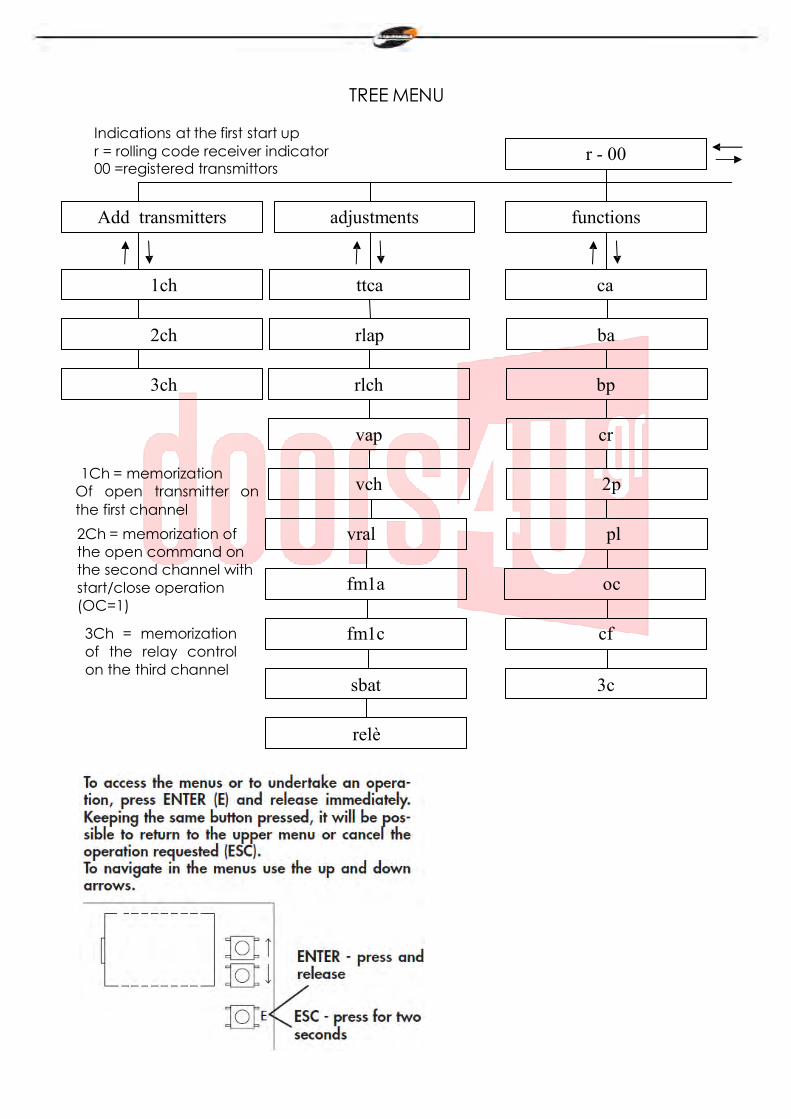
TREE MENU
Indications at the first start up r = rolling code receiver indicator 00 =registered transmittors
r - 00
Add transmitters adjustments functions
1ch ttca ca
2ch rlap ba
3ch rlch bp
vap cr
1Ch = memorization Of open transmitter on the first channel 2Ch = memorization of the open command on the second channel with start/close operation (OC=1)
3Ch = memorization of the relay control on the third channel
vch 2p
vral pl
fm1a oc
fm1c cf
sbat 3c
relè
23
language
Italiano
Français
English
Espagnol
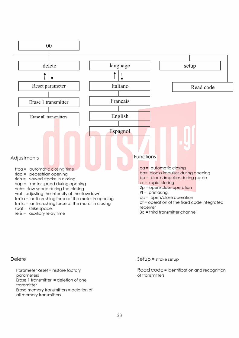
00
delete setup
Reset parameter Read code
Erase 1 transmitter
Erase all transmitters
Adjustments
ttca = automatic closing time rlap = pedestrian opening rlch = slowed stocke in closing vap = motor speed during opening vch= slow speed during the closing vral= adjusting the intensity of the slowdown fm1a = anti-crushing force of the motor in opening fm1c = anti-crushing force of the motor in closing sbat = strike space relè = auxiliary relay time
Functions
ca = automatic closing ba= blocks impulses during opening bp = blocks impulses during pause cr = rapid closing 2p = open/close operation Pl = preflasing oc = open/close operation cf = operation of the fixed code integrated receiver 3c = third transmitter channel
Delete
Parameter Reset = restore factory parameters Erase 1 transmitter = deletion of one transmitter Erase memory transmitters = deletion of all memory transmitters
Setup = stroke setup Read code = identification and recognition of transmitters
24
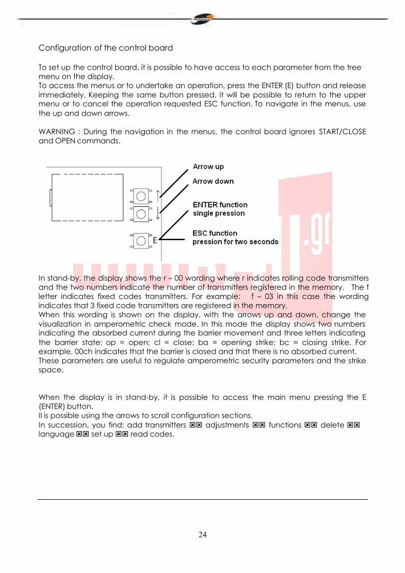
Configuration of the control board
To set up the control board, it is possible to have access to each parameter from the tree menu on the display. To access the menus or to undertake an operation, press the ENTER (E) button and release immediately. Keeping the same button pressed, it will be possible to return to the upper menu or to cancel the operation requested ESC function. To navigate in the menus, use the up and down arrows.
WARNING : During the navigation in the menus, the control board ignores START/CLOSE and OPEN commands.
In stand-by, the display shows the r – 00 wording where r indicates rolling code transmitters and the two numbers indicate the number of transmitters registered in the memory. The f letter indicates fixed codes transmitters. For example: f – 03 in this case the wording indicates that 3 fixed code transmitters are registered in the memory. When this wording is shown on the display, with the arrows up and down, change the visualization in amperometric check mode. In this mode the display shows two numbers indicating the absorbed current during the barrier movement and three letters indicating the barrier state: op = open; cl = close; ba = opening strike; bc = closing strike. For example, 00ch indicates that the barrier is closed and that there is no absorbed current. These parameters are useful to regulate amperometric security parameters and the strike space.
When the display is in stand-by, it is possible to access the main menu pressing the E (ENTER) button. Il is possible using the arrows to scroll configuration sections. In succession, you find: add transmitters adjustments functions delete language set up read codes.
25
Add transmitters
Before memorizing a transmitter, make sure that it is compatible with the type of receiver that is integrated (with the display in stand-by, r will appear for a rolling code receiver or f for a fixed code receiver). The receiver can memorize rolling codes type HCS300 STAGNOLI with billions of combinations or fixed codes type HT53200 with 13 bits or the fixed part of a rolling code (28 bits SN). It is possible to memorize up to 76 codes (different transmitters).
Enter the menu add transmitter pressing the E(ENTER) button, move over the wording display 1ch or 2ch or 3ch with the arrows and select the channel to be memorized. Press E (ENTER) button to confirm the channel to be memorized. Then press the button of the transmitter to be memorized when the press wording appears on the display. The wording ok will appear on the display if the operation has been carried out correctly or err if there are registration errors or full if the receiver memory is full. If nothing happens it means that the transmitter is not compatible.
An external antenna installed far from the ground, increases the visibility between the transmitter and the receiver. The power of the receiver can be reduced if metal parts or reinforced concrete are placed next to it.
Adjusments
Enter the Adjustment menu to regulate parameters. Choose the parameter to be regulated using the arrows and press the E(ENTER) button to see the registered value. Use the arrows to modify the parameter and confirm by pressing the E(ENTER) button. Press the E(ESC) button for about 2 seconds to exit from menus.
ttca (automatic closing time): this is the time from when the barrier is fully open to when it is closed automatically. If the photocell is engaged, the ttca time is counted from the time when the photocell is free. The default time set by Stagnoli is 10 sec and it can be regulated from 1 to 240 sec.
rlap (slowed stroke in opening): the control board slows down the stroke of the motor in the end part of its opening. The set up default stroke set is 50% and it can be regulated from 0 to 90. Regulate this value to prevent the barrier from having oscillations when it arrives at the end of the stroke in opening.
rlch (slowed stroke in closing): the control board slows down the stroke of the motor in the end part of its closing. The set up default stroke set is 50% and it can be regulated from 0 to 90. Regulate this value to prevent the barrier from having oscillations when it arrives at the end of the stroke in closing.
vap (opening motor speed): set the motor speed during the opening phase. The set up default speed set is 5 and it can be regulated from 1 to 10.
vch (closing motor speed): set the motor speed during the closing phase. The set up default speed set is 5 and it can be regulated from 1 to 10.
vral = adjusting the intensity of the slowdown) The set up default speed set is 5 and it can be regulated from 1 to 10.
26
fm1a (anti-crushing force in opening): this is the anti-crushing force of the barrier. The default value set by Stagnoli is 50 and it can be regulated from 10 to 99.
fm1c (anti-crushing force in closing): this is the anti-crushing force of the barrier. The default value set by Stagnoli is 50 and it can be regulated from 10 to 99.
WARNING: the way these two parameters are set can influence the level of safety of the system. Stagnoli advises setting this parameter with a safety margin that is at least +10 compared with the maximum current consumed by the motor in the opening and closing phases respectively. It is shown during the motor stroke on the display in the second main screen (amperometric control). fm1a and fm1c with low values, indicate greater anti-crushing sensibility. Too high values could detect an hard point as an obstacle and therefore a more elevated current absorption. At the end of the installation, check that the force of impact is in compliance with the regulation EN12453.
sbat (striking space): this is the percentage of the stroke individuated as strike space. In the area, the amperometric or encoder security will be detected as limit switch and not as obstacle. The default value set by Stagnoli is 10 and can be regulated from 5 to 20.
relé (auxiliary relay time): this is the time during which the auxiliary relay contact
remains closed after the barrier has closed. In case of active parameter 3c, this value indicates in how many seconds the auxiliary relay contact will be closed after having pressed the transmitter third channel.
27
Functions
Enter in the functions menu to regulate parameters. With the arrows choose the parameter to be modified and press the E(ENTER) button to see if the function is active (1) or not (0). Press the arrow buttons to modify. Then confirm pressing the E (ENTER) button and press the E (ESC) button for about 2 seconds to exit.
ca (automatic closing): automatic closing of the barrier after it has opened fully. Set ttca to adjust the time that must elapse between the end of the opening and the beginning of the automatic closing.
ba (impulse block during opening): the control board ignores the START impulses during the opening phase.
bp (block impulses during pause): the control board ignores START/CLOSE, OPEN impulses during the pause between the opening and the automatic closing. These functions are useful in case of many passages with many inputs in the same entry.
cr (rapid closing): activates the automatic rapid closing time after the passage through photocells during the opening phase or when the barrier is open. The ttca regulating time (if active and higher than ch r) is automatically reduced to ch r seconds.
2p (open/close operation): if active, at each START impulse, the movement of the barrier inverts the direction (OPENING – CLOSING). If not active, the barrier sequence of the barrier is OPENING – PAUSE (ttca) – CLOSING – STOP.
pl (preflashing): after the opening barrier command, the flasher or the courtesy light actives for two seconds before the opening or closing phase begins.
oc (open/close function): the START terminal input becomes OPEN. Activating this function, a command open the barrier and another command closes the barrier.
cf (operation of the fixed code integrated receiver): if active, the receiver works with fixed codes.
3c (third transmitter channel): if active, when the third channel is pressed, the auxiliary relay contact closes during the time, in seconds, set up in the relé parameter. Check to have registered in the memory the third transmitter channel).
28
Cancel It is possible in this menu to reset the factory settings or to cancel radio controls present in the memory. Enter in the cancel menu, chose the parameter with arrows buttons and confirm with the E (ENTER) button. Exit keeping pressed the E (ESC) button for about 2 seconds.
Parameter reset: to reset all regulating and functions values to the factory settings, go on the reset parameter wording and press the E(ENTER) button. The rese message is shown on the display, it flashes until the decision to reset all the parameters is confirmed with the E(ENTER) button or the operation is cancelled with the E( ESC) button.
erase 1 transmitter: to cancel a transmitter code, go to the wording 1 transmitter and press the (E ENTER) button. The message PRESS will appear. Press now the key of the transmitter that must be cancelled. If the operation has been carried out correctly, the message OK will appear. If this has not been put correctly, the message ERR will appear.
Erase all memory transmitters: to cancel all the recorded transmitters, go to the wording all memory transmitter and press the E (ENTER) button. The message prg will appear, it flashes until the decision to cancel all the recorded codes is confirmed by pressing E (ENTER) or the operation is cancelled by keeping the same key E(ESC) pressed for longer. N.B: To cancel the memory of the receiver, it is necessary to confirm twice the cancellation (erase memory transmitters and PRG).
Language
The display is available in four languages: italiano, français, english, espagnol. To chosen the operation language press the E (ENTER) button and go to the lingua menu with the arrows, then press the E(ENTER) button to enter in the menu. Go to the chosen language with the arrows and confirm pressing again the E(ENTER) button. To exit from the language menu, press for two seconds the E(ESC) button.
Learning
This operation allows the automation to automatically establish the start and end of a stroke identifying the respective mechanical strokes. Before proceeding with this operation, ensure that the barrier has been installed correctly and . Place the barrier at half stroke. Press E (ENTER) button to enter the menu, then with the arrows go to learning menu and press the E (ENTER) button. At this point the barrier will open (in case of closing, invert motor cables; if the barrier doesn’t close or open, check security devices and encoder connections), then it will close and will repeat this operation once more. The two first manoeuvres are to identify the beginning and the end of the motor stroke. The two following manoeuvres are to detect the motor absorption peak during the opening and closing of the barrier. In this phase, check the displayed values. These values, important for the amperometric security, are indicated by the a letter and two numbers on the display during the opening and by the b letter and two number during the closing. At the end of the Learning procedure, the wording ok will appear on the display if the operation has been carried out correctly or err if there are registration errors. Press the
29
E(ENTER) to exit from programming. Insert correctly in the menu anti-crushing force levels in opening and closing that must be upper than maximum values displayed during the learning. WARNING: this operation can influence on the automation security grade. During learning manoeuvres, the control board will ignore START, OPEN and CLOSE commands and will work with the maximum force parameters. Even if the safeties remain active, ensure that there are no objects or people in the area of operation of the barrier. Carry out some test working cycles checking the correct functioning of the whole installation. Measure the impact force of the barrier in respect with EN12445 norms dispositions.
Read code
It is possible to check if a code has already been memorized or to read the code of a new transmitter checking if it is compatible with the control board. Position yourself on the wording read code, press E(ENTER). When the display will show the message PRESS, press the transmitter key that must be checked.
• first screen: Sr01 or Sf01or –r01 or –f01 etc.. The first letter indicates the manufacturer of the radio control, where S means Stagnoli and - a generic manufacturer. The second letter indicates the type of code, where r indicates a rolling code and f a fixed code. The last two indicate the code of the key that was pressed.
• second screen : P_00, where P indicate the word “position” and the number that follows (progressive from 0 to 75) indicates the position occupied by the transmitter in the memory. If the transmitter is not found in the memory, the display will show ----.
• third and fourth screens : show the hexadecimal code of the transmitter.
N.B During the displaying of the wording press , when the transmitter key is pressed, if nothing changed on the display, it means that the transmitter is not compatible with the Stagnoli control board (make sure that the receiver is correctly inserted and that antenna is correctly mounted).
30
Statistics screens
The control board has three statistics screens that are viewed by keeping the key ENTER pressed once the display is in stand by: • first screen: d v1, where d indicates the motor Daphne at 24V and 01 the software version. • second and third screens: 0000 0000 indicate the number of complete manoeuvres undertaken by the control board
Diagnostic screens
The control board can recognize problems or alarms that occur in the system and can show them on the main display in stand by and not in amperometric checking:
o rf: activation of the OPEN command on the first radio frequency channel c rf: activation of the CLOSE command on the second radio frequency channel. iirf: activation of the 3ch command on the third radio frequency channel. sta: activation of the START command on the terminal input. stop: activation of the STOP command on the terminal input. open: activation of the OPEN command on the terminal input. clos: activation of the CLOSE command on the terminal input. pho: activation of the photocells input in closing on the terminal. phoa: activation of the photocells input in opening and in closing on the terminal. am 1: operation of amperometric sensor. enc1:operation of the sensor with encoder. encs: operation of the sensor with encoder on the slave (in synchronized mode). amps: operation of the amperometric sensor on the slave (in synchronized mode). e ac: communication of disturbed synchronization (in synchronized mode). n ac: No communication between master and slave (in synchronized mode).
31
Centrale de commande pour barrières Daphne 24V
F
D24 de Stagnoli est la centrale de commande étudiée pour les barrières Daphne 24V.
Réalisée seulement avec des matériels de premier choix, elle a été conçue pour avoir des absorptions basses au repos permettant ainsi une consommation d’énergie électrique basse. Une attention particulière a été portée aux professionnels du secteur en facilitant la programmation de la centrale grâce à un display en plusieurs langues (4 langues).
AVERTISSEMENTS ET NORMES DE SECURITE
Le présent manuel a été réalisé par Stagnoli pour une utilisation spécifique de la part d’un personnel professionnel et qualifié.
Nous conseillons de lire entièrement les instructions avant de procéder à l’installation du produit.
Durant le câblage, la tension sur l’installation doit être coupée.
Les installations de portails automatiques doivent être installées par un personnel technique qualifié et dans le respect des normes de loi.
DOUBLE SECURITE : La centrale est dotée de deux capteurs de sécurité : un encoder et un capteur ampérométrique.
Vérifier que la barrière soit solidement et bien fixée avec des attaches adaptées à l’automation Daphne.
Bien informer l’utilisateur final sur les modalités d’utilisation, sur le danger résiduel, sur la nécessité d’entretien et sur le besoin d’un contrôle des dispositifs de sécurité au moins tous les six mois.
32
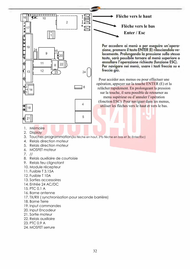
Flèche vers le haut
Flèche vers le bas Enter / Esc
Pour accéder aux menus ou pour effectuer une opération, appuyer sur la touche ENTER (E) et la relâcher rapidement. En prolongeant la pression
sur la touche, il sera possible de retourner au menu supérieur ou d’annuler l’opération
(fonction ESC). Pour naviguer dans les menus, utiliser les flèches vers le haut et vers le bas.
1. Mémoire 2. Display 3. Touches programmation(3a flèche en haut, 3°b flèche en bas et 3c Enter/Esc) 4. Relais direction moteur 5. Relais direction moteur 6. MOSFET moteur 7. // 8. Relais auxiliaire de courtoisie 9. Relais feu clignotant 10. Module récepteur 11. Fusible T 3.15A 12. Fusible T 10A 13. Sorties accessoires 14. Entrée 24 AC/DC 15. PTC 0.1 A 16. Borne antenne 17. TX/RX ( synchronisation pour seconde barrière) 18. Borne Terre 19. Input commandes 20. Input Encodeur 21. Sortie moteur 22. Relais auxiliaire 23. PTC 0.9 A 24. MOSFET serrure
33
19
13
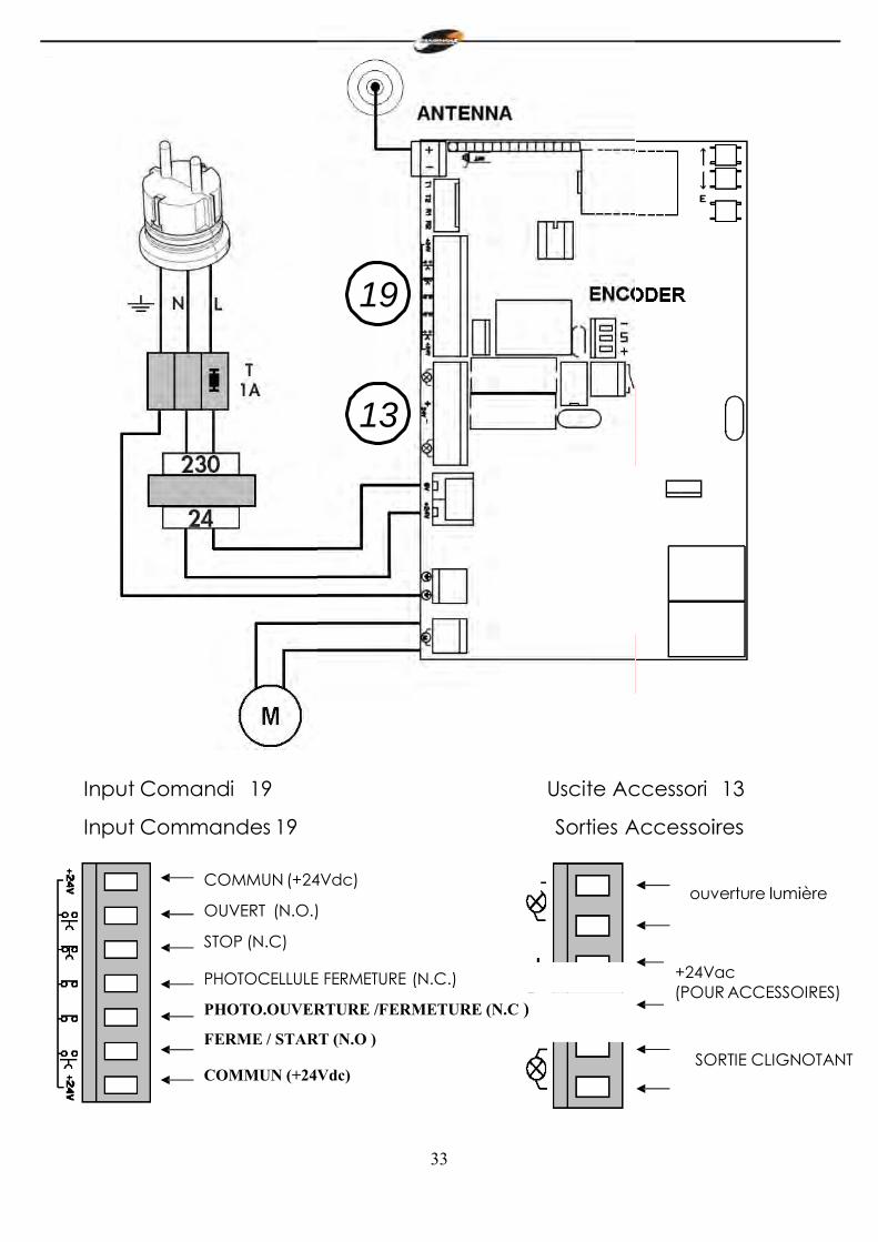
Input Comandi 19
Input Commandes 19
COMMUN (+24Vdc)
OUVERT (N.O.)
STOP (N.C)
PHOTOCELLULE FERMETURE (N.C.)
PHOTO.OUVERTURE /FERMETURE (N.C )
FERME / START (N.O )
COMMUN (+24Vdc)
Uscite Accessori 13
Sorties Accessoires
ouverture lumière
+24Vac (POUR ACCESSOIRES)
SORTIE CLIGNOTANT
34
La ligne d’alimentation 230V vers l’automatisme doit être protégée par un interrupteur magnétothermique ou bien par un couple de fusible d’1A. Un interrupteur différentiel est conseillé mais n’est pas indispensable si déjà présent en amont de l’installation.
Alimenter l’automatisme à travers un câble de 3x1,5mm2 (phase+neutre+terre). Si la distance entre la centrale et la connexion à l’installation à la terre dépasse les 30 m, il est nécessaire de prévoir un déperditeur de terre à proximité de la centrale.
Les câblages doivent être effectués lorsque l’alimentation 230V est débranchée. Les entrées des contacts de type N.C. (normalement fermé), si non utilisées, doivent être shuntées avec une borne commun (+24VDC). Si pour la même entrée, il existe plusieurs contacts N.C., ils doivent être branchés en série entre eux.
Les entrées des contacts de type N.O. (normalement ouvert), si non utilisées, doivent être laissées libres. Si pour la même entrée, il existe plusieurs contacts N.O., ils doivent être branchés en parallèle entre eux.
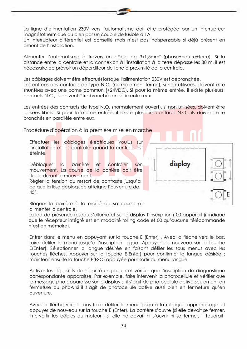
Procédure d’opération à la première mise en marche
Effectuer les câblages électriques voulus sur l’installation et les contrôler quand la centrale est éteinte.
Débloquer la barrière et contrôler son mouvement. La course de la barrière doit être fluide durant le mouvement. Régler la tension du ressort de contraste jusqu’à ce que la lisse débloquée atteigne l’ouverture de 45°.
Bloquer la barrière à la moitié de sa course et alimenter la centrale. La led de présence réseau s’allume et sur le display l’inscription r-00 apparait (r indique que le récepteur intégré est en modalité rolling code et 00 qu’aucune télécommande n’est en mémoire).
Entrer dans le menu en appuyant sur la touche E (Enter) . Avec la flèche vers le bas, faire défiler le menu jusqu’à l’inscription lingua. Appuyer de nouveau sur la touche E(Enter). Sélectionner la langue désirée en faisant défiler les sous menus avec les touches flèches. Appuyer sur la touche E(Enter) pour confirmer la langue désirée ; maintenir ensuite la touche E(ESC) appuyée pour sortir du menu langue.
Activer les dispositifs de sécurité un par un et vérifier que l’inscription de diagnostique correspondante apparaisse. Par exemple, faire intervenir la photocellule et vérifier que le message pho apparaisse sur le display si il s’agit de photocellule active seulement en fermeture ou phoA si il s’agit de photocellule active aussi bien en fermeture qu’en ouverture.
Avec la flèche vers le bas faire défiler le menu jusqu’à la rubrique apprentissage et appuyer de nouveau sur la touche E (Enter). La barrière s’ouvre (si elle devait se fermer, intervertir les câbles du moteur ; si elle ne devait ni s’ouvrir ni se fermer, il faudrait

35
vérifier que les sécurités et l’encodeur soient correctement branchés), puis elle se ferme et répète l’opération encore une fois. Les deux premières manœuvres servent à identifier le commencement et la fin de la course du moteur, les deux suivantes servent à relever le pic d’absorption du moteur durant l’ouverture et la fermeture de la barrière. Dans cette phase, il est nécessaire de contrôler les valeurs affichées sur le display. Ces valeurs, importantes pour la sécurité ampérométrique, sont indiquées par deux chiffres sur le display, précédés de la lettre a durant la phase d’ouverture et de la lettre c durant la phase de fermeture. A la fin de l’apprentissage, ok sera affiché sur le display si la programmation est correcte ou err si des erreurs ont été commises. Pour sortir de la programmation, appuyer pendant deux secondes sur la touche de sélection E(Esc). Programmer correctement les niveaux de force anti-écrasement en ouverture et en fermeture dans le menu, qui doivent être supérieures aux valeurs maximum affichées durant l’apprentissage. Ce réglage peut influencer le degré de sécurité de l’automation.
Durant les manœuvres d’apprentissage, la centrale ignore les commandes de START, OPEN (ouverture), CLOSE (fermeture) et travaille avec les paramètres de force au maximum. Même si les sécurités restent actives, s’assurer qu’aucun objet et que personne ne se trouve sur la trajectoire de travail de la barrière. l
Effectuer quelques cycles d’essai en vérifiant le bon fonctionnement de toute l’installation.
Prendre les mesures de la force d’impact de la barrière selon ce qui est spécifié par les normes EN12445
36
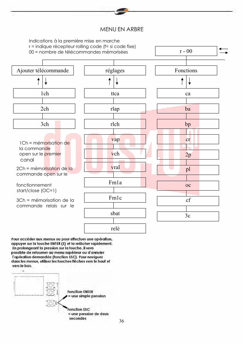
MENU EN ARBRE
Indications à la première mise en marche r = indique récepteur rolling code (f= si code fixe) 00 = nombre de télécommandes mémorisées r - 00
Ajouter télécommande réglages Fonctions
1ch ttca ca
2ch rlap ba
3ch rlch bp
1Ch = mémorisation de la commande open sur le premier canal
2Ch = mémorisation de la commande open sur le
fonctionnement start/close (OC=1)
3Ch = mémorisation de la commande relais sur le
vap cr
vch 2p
vral pl Fm1a oc
Fm1c cf
sbat 3c
relè
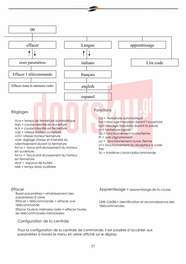
37
00
effacer Langue apprentissage
reset paramètres italiano Lire code
Effacer 1 télécommande français
Effacer toute la mémoire radio english
espanol
Réglages
ttca = temps de fermeture automatique rlap = course ralentie en ouverture rlch = course ralentie en fermeture vap = vitesse moteur ouverture vch= vitesse moteur fermeture vral= réglage vitesse et intensité du ralentissement durant la fermeture fm1a = force anti-écrasement du moteur en ouverture fm1c = force anti-écrasement du moteur en fermeture sbat = espace de butée relé = temps relais auxiliaire
Fonctions
ca = fermeture automatique ba = blocage impulsion durant l’ouverture bp= blocage impulsion durant la pause cr = fermeture rapide 2p = fonctionnement ouvre/ferme Pl = pré-clignotement oc = fonctionnement ouvre /ferme cf = fonctionnement du récepteur à code fixe 3c = troisième canal radiocommande
Effacer Reset paramètres = rétablissement des paramètres d’usine Effacer 1 télécommande = effacer une télécommande Effacer toute la mémoire radio = effacer toutes les télécommandes mémorisées
Apprentissage = apprentissage de la course Lire code = identification et reconnaissance des télécommandes
Configuration de la centrale
Pour la configuration de la centrale de commande, il est possible d’accéder aux paramètres à travers le menu en arbre affiché sur le display.
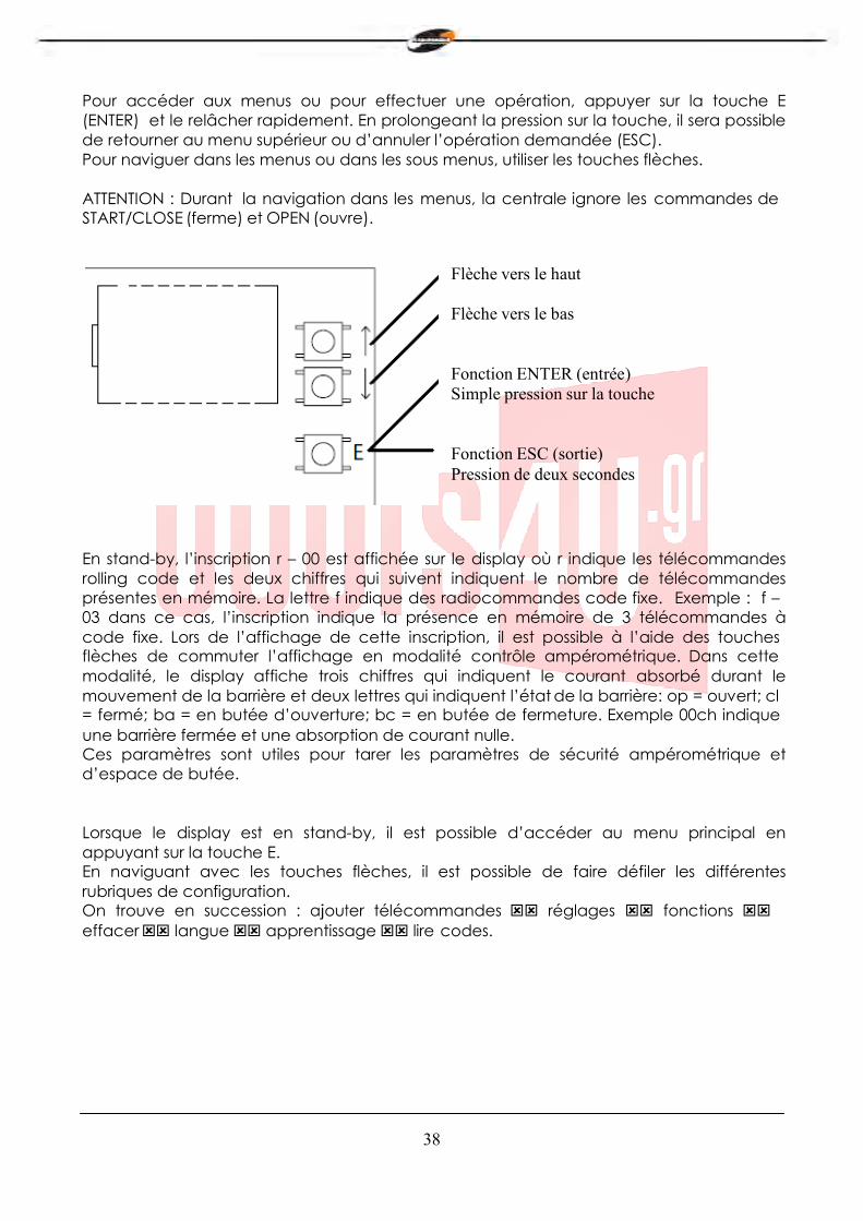
38
Pour accéder aux menus ou pour effectuer une opération, appuyer sur la touche E (ENTER) et le relâcher rapidement. En prolongeant la pression sur la touche, il sera possible de retourner au menu supérieur ou d’annuler l’opération demandée (ESC). Pour naviguer dans les menus ou dans les sous menus, utiliser les touches flèches.
ATTENTION : Durant la navigation dans les menus, la centrale ignore les commandes de START/CLOSE (ferme) et OPEN (ouvre).
Flèche vers le haut
Flèche vers le bas
Fonction ENTER (entrée) Simple pression sur la touche
Fonction ESC (sortie) Pression de deux secondes
En stand-by, l’inscription r – 00 est affichée sur le display où r indique les télécommandes rolling code et les deux chiffres qui suivent indiquent le nombre de télécommandes présentes en mémoire. La lettre f indique des radiocommandes code fixe. Exemple : f – 03 dans ce cas, l’inscription indique la présence en mémoire de 3 télécommandes à code fixe. Lors de l’affichage de cette inscription, il est possible à l’aide des touches flèches de commuter l’affichage en modalité contrôle ampérométrique. Dans cette modalité, le display affiche trois chiffres qui indiquent le courant absorbé durant le mouvement de la barrière et deux lettres qui indiquent l’état de la barrière: op = ouvert; cl = fermé; ba = en butée d’ouverture; bc = en butée de fermeture. Exemple 00ch indique une barrière fermée et une absorption de courant nulle. Ces paramètres sont utiles pour tarer les paramètres de sécurité ampérométrique et d’espace de butée.
Lorsque le display est en stand-by, il est possible d’accéder au menu principal en appuyant sur la touche E. En naviguant avec les touches flèches, il est possible de faire défiler les différentes rubriques de configuration. On trouve en succession : ajouter télécommandes réglages fonctions effacer langue apprentissage lire codes.
39
Ajouter télécommandes
Avant de mémoriser une télécommandes, s’assurer que la télécommande soit compatible avec la typologie de récepteur intégré (avec display au repos, la lettre r sera affichée s’il s’agit d’un récepteur en modalité rolling code ou f s’il s’agit d’un récepteur en modalité code fixe). Le récepteur peut mémoriser des codes rolling codes de type HCS300 STAGNOLI avec des milliards de combinaisons ou codes fixes de type HT53200 à 13 bit ou la partie fixe d’un code rolling code (28 bit SN). Il est possible de mémoriser jusqu’à 76 codes (télécommandes différentes).
Entrer dans le sous menu ajouter télécommande en appuyant sur la touche E(ENTER), choisir le canal à mémoriser en se portant sur l’inscription sur le display 1ch ou 2ch ou 3ch à l’aide des touches flèches. Appuyer sur la touche E(ENTER) pour confirmer le canal à mémoriser. Appuyer ensuite sur la touche de la télécommande que l’on veut mémoriser quand l’inscription premi (appuyer) apparait à l’écran : l’inscription ok sera ensuite affichée à l’écran si l’opération a été effectuée correctement, l’inscription err en cas d’erreur d’enregistrement ou full si la mémoire du récepteur est pleine. Si aucune inscription n’apparait, la télécommande utilisée ne rentre pas dans le standard adopté par Stagnoli.
En installant une antenne extérieure à la centrale et loin du sol, la zone de visibilité entre télécommandes et centrale augmente. Les pièces métalliques et en ciment armé, si placées entre la centrale et le récepteur, diminuent la capacité de réception.
Réglages
Les réglages des paramètres s’effectuent en entrant dans le sous menu réglages. Choisir le paramètre à modifier à l’aide des touches flèches et appuyer sur E(ENTER) pour visualiser la valeur programmée. Utiliser les touches flèches pour modifier le paramètre et confirmer avec la touche E(ENTER). Pour sortir des menus, maintenir la touche E(ESC) appuyée pendant environ 2 secondes.
ttca (temps de fermeture automatique) : c’est le temps qui s’écoule entre l’ouverture complète de la barrière et sa fermeture qui se produit en mode automatique. Si la photocellule est occupée, le temps de ttca est calculé à partir du moment où la photocellule se libère. Le temps de défaut programmé par Stagnoli est de 10 sec. et est réglable de 1 à 240 sec.
rlap (course ralentie en ouverture)= la centrale ralentit la course du moteur dans la partie finale de sa phase d’ouverture. Le ralentissement programmé par défaut par Stagnoli est de 50 % de la course et le paramètre est réglable de 0 à 90. Programmer cette valeur de façon à ce que la barrière ne présente pas d’oscillations fortes lors de son arrivée en fin de course en ouverture.
rlch (course ralentie en fermeture)= la centrale ralentit la course du moteur dans la partie finale de sa phase de fermeture. Le ralentissement programmé par Stagnoli est de 50 % de la course et ce paramètre est réglable de 0 à 90. Programmer cette valeur de façon à ce que la barrière ne présente pas d’oscillations fortes lors de son arrivée en fin de course en fermeture.
40
vap (vitesse moteur ouverture) : programmer la vitesse du moteur durant sa phase d’ouverture. La vitesse de défaut est 5 et est réglable de 1 à 10.
vch. (vitesse moteur fermeture) : programmer la vitesse du moteur durant sa phase de fermeture. La vitesse de défaut est 5 et est réglable de 1 à 10.
Vral : (Vitesse de ralentissement durant la fermeture) : programmer la vitesse du moteur durant la phase de ralentissement en fermeture. La vitesse programmée par défaut est 5 et est réglable de 1 à 10.
fm1a (force anti-écrasement du moteur en ouverture) : c’est la force anti-écrasement de la barrière. La force programmée par défaut est 50 et peut être réglée de 10 à 90.
fm1c (force anti-écrasement du moteur en fermeture) : c’est la force anti-écrasement de la barrière. La force programmée par défaut est 50 et peut être réglée de 10 à 90.
ATTENTION : la programmation de ces deux paramètres peut influencer le degré de sécurité de l’installation. Nous conseillons de programmer ces paramètres avec une marge de sécurité qui soit au moins de + 10 par rapport au maximum du courant consommé par le moteur respectivement en phase d’ouverture et de fermeture. Le courant absorbé durant la course du moteur peut être lu sur le display – deuxième page principale (contrôle ampérométrique). fm1a et fm1c, avec des valeurs basses, indiquent une plus grande sensibilité à l’anti- écrasement. Des valeurs trop basses peuvent relever comme obstacle un point dur durant le mouvement et donc d’absorption de courant plus élevé. Vérifier après avoir installé la barrière que les forces d’impact respectent la norme EN12453.
sbat (espace de butée) : c’est le pourcentage de la course déterminée comme espace de butée. Dans cette zone, la sécurité encoder ou ampérométrique sera relevée comme fin de course et non comme obstacle. La valeur programmée par défaut est 10 et peut être réglée de 5 à 20.
relè (temps relais auxiliaire) : c’est le temps durant lequel le contact du relais auxiliaire reste fermé après que la barrière se soit fermée. En cas de paramètre 3c actif cette valeur indique le nombre de secondes pendant lesquelles le contact relais auxiliaire restera fermé après avoir appuyé sur le troisième canal de la télécommande.
41
Fonctions
Les réglages des paramètres se font en entrant dans le sous menu fonctions. Choisir le paramètre à modifier à l’aide des touches flèches et appuyer sur E(ENTER) pour visualiser si la fonction est active (1) ou si elle est désactivée (0). Pour modifier l’état, appuyer sur les touches flèches. Confirmer ensuite à l’aide de la touche E(ENTER) et sortir en maintenant la touche E(ESC) appuyée pendant 2 secondes.
ca (fermeture automatique): fermeture automatique de la barrière après son ouverture complète. Programmer le paramètre ttca pour personnaliser le temps qui doit s’écouler entre la fin de l’ouverture et de commencement de la fermeture automatique.
ba (blocage impulsion durant l’ouverture) : la centrale ignore les impulsions de START durant la phase d’ouverture.
bp (blocage impulsions durant la pause): la centrale ignore les impulsions de START/CLOSE, OPEN durant la pausa entre l’ouverture et la fermeture automatique. Ces fonctions sont utiles en cas de différents passages avec différentes commandes sur la même entrée.
cr (fermeture rapide) : active le temps de fermeture rapide automatique après le passage à travers les photocellules durant la phase d’ouverture ou quand la barrière est ouverte. Le temps du réglage ttca (si activé et supérieur à ch r) est automatiquement réduit au temps ch r programmé.
2p (fonctionnement ouvre/ferme) : si actif, à chaque impulsion de START, le mouvement de la barrière change la direction (OUVERTURE - FERMETURE). Si désactivé, la séquence de mouvement de la barrière devient OUVERTURE – ARRET (ttca) - FERMETURE - STOP.
pl (pré-clignotement): après la commande d’ouverture de la barrière, le clignotement ou la lumière de courtoisie s’activent pendant deux secondes avant que la phase d’ouverture ou de fermeture ne commence.
oc (fonctionnement ouvre/ferme) : l’entrée sur la plaque à bornes de START devient CLOSE (FERME). Dans cette modalité une commande ouvre la barrière, l’autre la ferme.
cf (fonctionnement du récepteur intégré à code fixe) : si actif, le récepteur fonctionne avec les codes fixes.
3c (troisième canal radiocommande) : si actif, en appuyant sur le troisième canal de la télécommande, le contact du relais auxiliaire, le contact du relais auxiliaire se ferme pendant le temps programmé dans le paramètre relé.
sc (voyant barrière ouverte) : si actif, la sortie serrure électrique/magnétique devient la sortie voyant barrière ouverte. Tant que la barrière reste ouverte, cette sortie restera active à +24VDC. ms (maitre): activer cette fonction si on veut que la centrale devienne master (maitre) dans une configuration à deux barrières (voir paragraphe synchronisation). De cette manière, la centrale reçoit les commandes d’ouverture fermeture et les photocellules
42
selon le câblage effectué et transmet à la centrale slave (esclave) les commandes pour contrôler le mouvement. ATTENTION : ne pas activer les deux paramètres ms et sl.
sl (esclave): activer cette fonction si on veut que la centrale devienne slave (esclave) dans une configuration à deux barrières (voir paragraphe synchronisation). De cette manière les commandes d’ouverture, fermeture et les photocellules sont reçues par la centrale master (maitre) qui contrôle les mouvements. ATTENTION : ne pas activer les deux paramètres ms et sl.
Effacer
Dans ce sous menu, il est possible de rétablir les paramètres d’usine ou d’effacer les radiocommandes présentes en mémoire. En entrant dans le sous menu cancella (effacer) choisir la rubrique désirée à l’aide des touches flèches et confirmer avec la touche E(ENTER). Sortir en maintenant la touche E(ESC) appuyée pendant environ 2 secondes.
reset paramètres : pour reprogrammer toutes les valeurs et les fonctions à la sortie d’usine, appuyer sur la touche E(ENTER) et se porter sur la rubrique reset parametri (reset paramètres) du sous menu et appuyer sur la touche E(ENTER). Le message rese sera affiché et clignotera jusqu’à ce que l’intention de reprogrammer tous les paramètres par l’intermédiaire de la touche E(ENTER) ou d’annuler l’opération par l’intermédiaire de la touche E(ESC) n’aura pas été confirmé.
effacer 1 radiocommande= pour effacer le code d’un émetteur, une fois entré
dans le menu effacer, se porter sur l’inscription effacer 1 radiocommande sur le display et appuyer sur la touche E (ENTER). Le message PREMI (APPUYER) sera affiché. Appuyer alors sur la touche de l’émetteur à effacer. Si l’opération est correctement menée à terme, le message OK sera affiché. Dans le cas contraire, ERR sera affiché.
effacer toute la mémoire radio= pour effacer tous les émetteurs enregistrés,
une fois entré dans le menu effacer, se porter sur l’inscription effacer toute la mémoire radio sur le display et appuyer sur la touche E(ENTER). Le message prg sera affiché et clignotera tant que l’intention d’effacer tous les codes enregistrés en appuyant sur la touche E(ENTER) ou d’annuler l’opération en prolongeant la pression de la touche E(ESC), ne sera pas confirmée. N.B : Pour porter l’effacement de la mémoire radio à terme, il est demandé de confirmer deux fois la volonté d’effacer(effacer toute la mémoire radio et PRG).
43
Langue Les messages sur le display peuvent être affichés en plusieurs langues: italien, francais, anglais et espagnol. Pour choisir la langue de fonctionnement, se porter sur le menu langue et appuyer sur E(ENTER). Se porter alors, en passant par le sous menu lingua et confirmer en appuyant de nouveau sur E(ENTER). Se porter sur la langue désirée à l’aide des flèches et confirmer en appuyant sur E(ENTER). Pour sortir du menu langue appuyer pendant deux secondes sur la touche E(ESC).
Synchronisation
Il est possible avec deux centrales Daphne de configurer deux barrières de manière synchronisée pour permettre de doubler la longueur de l’ouverture. Dans cette modalité, les deux centrales communiquent via câble (à 4 pôles) pour synchroniser les mouvements. Une centrale (master - maitre) sera à la commande de l’ouverture alors que la deuxième centrale (slave-esclave) effectuera les commandes envoyées par la centrale de commande. Les photocellules et les commandes d’entrée doivent être branchées uniquement à la centrale master. Les systèmes de sécurité encodeur et ampérométrique de la centrale slave seront de toute façon actifs. Le câble de branchement entre les deux centrales qui permet la synchronisation doit être raccordé à la borne M2(voir figure 1 composant 17) en branchant la sortie TX du master (T1-T2) avec l’entrée RX du slave (R1-R2) et vice versa. Activer les paramètres correspondants de master et slave comme décrit dans le paragraphe menu fonctions.
Pages-écrans de diagnostic La centrale est en mesure de reconnaitre les problèmes ou les alarmes qui peuvent se produire sur l’installation et pour lesquels elle peut signaler certains messages sur le display pour permettre de déterminer le problème: o rf: activation de la commande OPEN sur le premier canal de radiofréquence. c rf: activation de la commande CLOSE (ferme) sur le deuxième canal de radiofréquence. iirf: activation de la commande 3ch sur le troisième canal de radiofréquence. sta: activation de la commande de START sur l’entrée de la plaque à bornes. stop: activation de la commande de STOP sur l’entrée de la plaque à bornes. open: activation de la commande de OPEN sur l’entrée de la plaque à bornes. clos: activation de la commande de CLOSE sur l’entrée de la plaque à bornes. pho: activation de l’entrée des photocellules en fermeture sur la plaque à bornes. phoa: activation de l’entrée des photocellules en ouverture et en fermeture sur la plaque à bornes. am 1: intervention du détecteur ampérométrique. enc1: intervention du détecteur à encodeur. encs: intervention du détecteur à encoder sur le slave (en modalité synchronisée). amps: intervention du détecteur ampérométrique sur le slave (en modalité synchronisée). e ac: communication de synchronisation perturbée (en modalité synchronisée). n ac: communication entre master et slave absente (en modalité synchronisée).

44
X61Al633 Rev.S-11-13
StagnoliT.G. sri
Via Mantova,trav.I, 105A/B +39.0309139511

+39.0309139580 [email protected] www.stagnoli.com