SR en 1317-2 Din 2010 Dispozitive de Protectie La Drumuri
29
ICS 13.200; 93.080.30 STANDARD ROMÂN SR EN 1317-2 Octombrie 2010 Dispozitive de protecĠie la drumuri Partea 2: Clase de performanĠă, criterii de acceptare a încercărilor la úoc úi metode de încercare a parapetelor de siguranĠă Road restraint systems. Part 2: Performance classes, impact test acceptance criteria and test methods for safety barriers including vehicle parapets Dispositifs de retenue routiers. Partie 2: Classes de performance, critères d' acceptation des essais de choc et méthodes d' essai pour les barrières de sécurité incluant les barrières de bord d' ouvrage d' art APROBARE Aprobat de Directorul General al ASRO la 31 octombrie 2010 Standardul european EN 1317-2:2010 a fost adoptat prin metoda notei de confirmare şi are statutul unui standard român Înlocuieşte SR EN 1317-2:2000, SR EN 1317-2:2000/A1:2006 şi SR EN 1317-2:2000/C91:2009 CORESPONDENŢĂ Acest standard este identic cu standardul european EN 1317-2:2010 This standard is identical with the European Standard EN 1317-2:2010 La présente norme est identique à la Norme européenne EN 1317-2:2010 ASOCIAğIA DE STANDARDIZARE DIN ROMÂNIA (ASRO) Str. Mendeleev nr. 21-25, cod 010362, Bucureşti Director General: Tel.: +40 21 316 32 96, Fax: +40 21 316 08 70 Direcţia Standardizare: Tel. +40 21 310 17 30, +40 21 310 43 08, +40 21 312 47 44, Fax: +40 21 315 58 70 Direcţia Publicaţii- Serv. Vânzări/Abonamente: Tel. +40 21 316 77 25, Fax + 40 21 317 25 14, +40 21 312 94 88 Serviciul Redacţie-Marketing, Drepturi de Autor: Tel.: + 40 21 316.99.74 © ASRO Reproducerea sau utilizarea integrală sau parţială a prezentului standard în orice publicaţii şi prin orice procedeu (electronic, mecanic, fotocopiere, microfilmare etc.) este interzisă dacă nu există acordul scris al ASRO Ref.: SR EN 1317-2:2010 Ediţia 2 Pagina tiparita cu aplicatia InfoStandard (c) 2008 ASRO (www.asro.ro) & SKY PROJECT (www.skyproject.ro). Asociatia de Standardizare din Romania, REF 4-319 / 2011-02-07 GIROD SEMNALIZARE RUTIERA SRL
-
Upload
adrian-constantin -
Category
Documents
-
view
665 -
download
72
Transcript of SR en 1317-2 Din 2010 Dispozitive de Protectie La Drumuri
ICS 13.200; 93.080.30
STANDARD ROMÂN
SR EN 1317-2 Octombrie 2010
Dispozitive de protec ie la drumuri Partea 2: Clase de performan , criterii de acceptare a încerc rilor la oc i metode de încercare a parapetelor de siguran
Road restraint systems. Part 2: Performance classes, impact test
acceptance criteria and test methods for safety barriers including vehicle parapets
Dispositifs de retenue routiers. Partie 2: Classes de performance,
critères d' acceptation des essais de choc et méthodes d' essai pour les barrières de sécurité incluant les barrières de bord d' ouvrage d' art
APROBARE Aprobat de Directorul General al ASRO la 31 octombrie 2010 Standardul european EN 1317-2:2010 a fost adoptat prin metoda notei de confirmare şi are statutul unui standard român Înlocuieşte SR EN 1317-2:2000, SR EN 1317-2:2000/A1:2006 şi SR EN 1317-2:2000/C91:2009
CORESPONDENŢĂ Acest standard este identic cu standardul european EN 1317-2:2010 This standard is identical with the European Standard EN 1317-2:2010 La présente norme est identique à la Norme européenne EN 1317-2:2010
ASOCIA IA DE STANDARDIZARE DIN ROMÂNIA (ASRO) Str. Mendeleev nr. 21-25, cod 010362, Bucureşti
Director General: Tel.: +40 21 316 32 96, Fax: +40 21 316 08 70 Direcţia Standardizare: Tel. +40 21 310 17 30, +40 21 310 43 08, +40 21 312 47 44, Fax: +40 21 315 58 70
Direcţia Publicaţii- Serv. Vânzări/Abonamente: Tel. +40 21 316 77 25, Fax + 40 21 317 25 14, +40 21 312 94 88 Serviciul Redacţie-Marketing, Drepturi de Autor: Tel.: + 40 21 316.99.74
© ASRO Reproducerea sau utilizarea integrală sau parţială a prezentului standard în orice publicaţii şi prin orice procedeu (electronic, mecanic, fotocopiere, microfilmare etc.) este interzisă dacă nu există acordul scris al ASRO
Ref.: SR EN 1317-2:2010 Ediţia 2
Pagina tiparita cu aplicatia InfoStandard (c) 2008 ASRO (www.asro.ro) & SKY PROJECT (www.skyproject.ro).Asociatia de Standardizare din Romania, REF 4-319 / 2011-02-07 GIROD SEMNALIZARE RUTIERA SRL

EUROPEAN STANDARD
NORME EUROPÉENNE
EUROPÄISCHE NORM
EN 1317-2
July 2010
ICS 13.200; 93.080.30 Supersedes EN 1317-2:1998
English Version
Road restraint systems - Part 2: Performance classes, impact test acceptance criteria and test methods for safety barriers
including vehicle parapets
Dispositifs de retenue routiers - Partie 2: Classes de performance, critères d'acceptation des essais de choc et
méthodes d'essai pour les barrières de sécurité incluant les barrières de bord d'ouvrage d'art
Rückhaltesysteme an Straßen - Teil 2: Leistungsklassen, Abnahmekriterien für Anprallprüfungen und Prüfverfahren
für Schutzeinrichtungen und Fahrzeugbrüstungen
This European Standard was approved by CEN on 29 April 2010. CEN members are bound to comply with the CEN/CENELEC Internal Regulations which stipulate the conditions for giving this European Standard the status of a national standard without any alteration. Up-to-date lists and bibliographical references concerning such national standards may be obtained on application to the CEN Management Centre or to any CEN member. This European Standard exists in three official versions (English, French, German). A version in any other language made by translation under the responsibility of a CEN member into its own language and notified to the CEN Management Centre has the same status as the official versions. CEN members are the national standards bodies of Austria, Belgium, Bulgaria, Croatia, Cyprus, Czech Republic, Denmark, Estonia, Finland, France, Germany, Greece, Hungary, Iceland, Ireland, Italy, Latvia, Lithuania, Luxembourg, Malta, Netherlands, Norway, Poland, Portugal, Romania, Slovakia, Slovenia, Spain, Sweden, Switzerland and United Kingdom.
EUROPEAN COMMITTEE FOR STANDARDIZATION C O M I T É E U R O P É E N D E N O R M A LI S A T I O N EUR OP ÄIS C HES KOM ITEE FÜR NOR M UNG
Management Centre: Avenue Marnix 17, B-1000 Brussels
© 2010 CEN All rights of exploitation in any form and by any means reserved worldwide for CEN national Members.
Ref. No. EN 1317-2:2010: E
Pagina tiparita cu aplicatia InfoStandard (c) 2008 ASRO (www.asro.ro) & SKY PROJECT (www.skyproject.ro).Asociatia de Standardizare din Romania, REF 4-319 / 2011-02-07 GIROD SEMNALIZARE RUTIERA SRL
EN 1317-2:2010 (E)
2
Contents Page
Foreword ...................................................................................................................................................................... 3
Introduction ................................................................................................................................................................. 6
1 Scope .............................................................................................................................................................. 7
2 Normative references .................................................................................................................................... 7
3 Performance classes ..................................................................................................................................... 73.1 General ............................................................................................................................................................ 73.2 Containment levels ........................................................................................................................................ 73.3 Impact severity ............................................................................................................................................... 93.4 Location of the ATD ....................................................................................................................................... 93.5 Deformation of the restraint system ............................................................................................................ 93.6 Vehicle pedestrian parapets ....................................................................................................................... 13
4 Impact test acceptance criteria .................................................................................................................. 134.1 General .......................................................................................................................................................... 134.2 Safety barrier including vehicle parapet behaviour ................................................................................. 144.3 Test vehicle behaviour ................................................................................................................................ 154.4 Severity Index ............................................................................................................................................... 174.5 Test vehicle deformation ............................................................................................................................ 174.6 Safety barrier deformation .......................................................................................................................... 174.7 Tests for system type tested safety barriers (Families of barriers) ....................................................... 17
5 Test methods ................................................................................................................................................ 175.1 Test site ........................................................................................................................................................ 175.2 Test vehicles ................................................................................................................................................ 185.3 Safety barrier ................................................................................................................................................ 185.3.1 General .......................................................................................................................................................... 185.3.2 Installation .................................................................................................................................................... 185.3.3 Position of the impact point ....................................................................................................................... 185.4 Accuracies and limit deviations of impact speeds and approach angle ............................................... 185.4.1 Vehicle impact speed .................................................................................................................................. 185.4.2 Vehicle approach angle ............................................................................................................................... 195.4.3 Combined limit deviation of speed and angle .......................................................................................... 195.5 Vehicle instrumentation .............................................................................................................................. 195.6 Photographic coverage ............................................................................................................................... 20
6 Test report .................................................................................................................................................... 21
Annex A (normative) Detailed Test Report Template ............................................................................................ 22
Annex B (informative) Criteria for sufficient test length evaluation .................................................................... 27
Bibliography .............................................................................................................................................................. 28
Pagina tiparita cu aplicatia InfoStandard (c) 2008 ASRO (www.asro.ro) & SKY PROJECT (www.skyproject.ro).Asociatia de Standardizare din Romania, REF 4-319 / 2011-02-07 GIROD SEMNALIZARE RUTIERA SRL

EN 1317-2:2010 (E)
3
Foreword
This document (EN 1317-2:2010) has been prepared by Technical Committee CEN/TC 226 “Road equipment”, the secretariat of which is held by AFNOR.
This European Standard shall be given the status of a national standard, either by publication of an identical text or by endorsement, at the latest by January 2011, and conflicting national standards shall be withdrawn at the latest by January 2011.
Attention is drawn to the possibility that some of the elements of this document may be the subject of patent rights. CEN [and/or CENELEC] shall not be held responsible for identifying any or all such patent rights.
This document supersedes EN 1317-2:1998.
This document has been prepared under a mandate given to CEN by the European Commission and the European Free Trade Association, and supports essential requirements of EU Directive(s).
EN 1317 consists of the following parts:
⎯ EN 1317-1, Road restraint systems ⎯ Part 1: Terminology and general criteria for test methods;
⎯ EN 1317-2, Road restraint systems ⎯ Part 2: Performance classes, impact test acceptance criteria and test methods for safety barriers including vehicle parapets;
⎯ EN 1317-3, Road restraint systems ⎯ Part 3: Performance classes, impact test acceptance criteria and test methods for crash cushions;
⎯ ENV 1317-4, Road restraint systems Part 4: Performance classes, impact test acceptance criteria and test methods for terminals and transitions of safety barriers;
⎯ prEN 1317-4, Road restraint systems ⎯ Part 4: Performance classes, impact test acceptance criteria and test methods for transitions of safety barriers (under preparation: this document will supersede ENV 1317-4:2001 for the clauses concerning transitions);
⎯ EN 1317-5, Road restraint systems ⎯ Part 5: Product requirements and evaluation of conformity for vehicle restraint systems;
⎯ prEN 1317-6, Road restraint systems ⎯ Pedestrian restraint systems Part 6: Pedestrian Parapet (under preparation);
⎯ prEN 1317-7, Road restraint systems ⎯ Part 7: Performance classes, impact test acceptance criteria and test methods for terminals of safety barriers (under preparation: this document will supersede ENV 1317-4:2001 for the clauses concerning terminals);
⎯ prEN 1317-8, Road restraint systems ⎯ Part 8: Motorcycle road restraint systems which reduce the impact severity of motorcyclist collisions with safety barriers (under preparation).
Annex A is normative and Annex B is informative.
The significant technical changes incorporated in this revision are:
3.2 Containment levels
Pagina tiparita cu aplicatia InfoStandard (c) 2008 ASRO (www.asro.ro) & SKY PROJECT (www.skyproject.ro).Asociatia de Standardizare din Romania, REF 4-319 / 2011-02-07 GIROD SEMNALIZARE RUTIERA SRL
EN 1317-2:2010 (E)
4
In Table 2 the new containment classes L1, L2, L3, L4a and L4b have been added, requiring the same tests of the corresponding H classes plus the test TB 32.
3.3 Impact severity
The requirement for the index PHD (Post impact Head Deceleration) has been cancelled. Only ASI and THIV are required.
3.5 Deformation of the restraint system
New requirement on the accuracy of measurement of Dynamic Deflection and Working Width:
The accuracy required for the measurement of the dynamic deflection and for the working width shall be 10 % but not less than 0,1 m.
New definition of vehicle intrusion (VI).
New definitions of Normalised Dynamic Deflection DN, Normalised Working Width WN and Normalised Vehicle Intrusion VIN.
Table 4 – Levels of working width based on the normalised values
Table 5 – Levels of normalised vehicle intrusion (new item)
4 Impact test acceptance criteria
Table 6 – Safety barrier test parameters includes containment levels L
4.2 Safety barrier including parapet behaviour
The first two sentences of the paragraph in the 1998 text:
The safety barrier shall contain and redirect the vehicle without complete breakage of the principal longitudinal elements of the system.
No major part of the safety barrier shall become totally detached or present an undue hazard to other traffic, pedestrians or personnel in a work zone.
are replaced by:
The safety barrier including parapet shall contain the vehicle without complete breakage of any of the principal longitudinal elements of the system.
All totally detached parts of the safety barrier with a mass greater than 2,0 kg shall be identified, located and recorded in the test report with their size.
4.3 Test vehicle behaviour
The first two sentences of the paragraph in the 1998 text:
The centre of gravity of the vehicle shall not cross the centreline of the deformed system.
The vehicle shall remain upright during and after impact, although moderate rolling, pitching and yawing are acceptable.
are replaced by:
Pagina tiparita cu aplicatia InfoStandard (c) 2008 ASRO (www.asro.ro) & SKY PROJECT (www.skyproject.ro).Asociatia de Standardizare din Romania, REF 4-319 / 2011-02-07 GIROD SEMNALIZARE RUTIERA SRL
EN 1317-2:2010 (E)
5
During and after the impact, no more than one of the wheels of the vehicle shall completely pass over or under the safety barrier.
The vehicle shall not roll over (including rollover of the vehicle onto its side) during or after impact.
For tests with HGVs and buses, not more than 5 % of the mass of the ballast shall become detached or be spilt during the test up to the time when the wheel tracks of the vehicle leaves the exit box.
4.4 Severity Index
The requirement for the index PHD (Post impact Head Deceleration) has been cancelled. Only ASI and THIV are required.
4.7 Tests for system type tested safety barriers (Families of barriers)
New specifications for families of barriers.
5 Test methods
The specifications of 5.1 "Test Site" and 5.2 "Test Vehicles" are moved to Part 1.
5.3.2 Installation
This subclause has been entirely revised with detailed requirements on the test length, end anchorages, pretensioned systems and infilling of vehicle pedestrian parapets.
5.3.3 Position of the impact point
New requirement:
If the test house chooses an impact point other than that at a point about one third of the installation length, in order to ensure worst-case conditions, then this choice shall be justified in the test report.
5.5 Vehicle instrumentation
The specifications of 5.5 are moved to Part 1.
5.6 Photographic coverage
New requirement:
Normal speed cameras shall be operated at a minimum of 24 frames per second.
Annex A – Detailed Test Report Template
New normative item.
Annex B – Criteria for sufficient test length evaluation
New informative item on a possible criterion to evaluate the adequacy of the length of the test installation.
According to the CEN/CENELEC Internal Regulations, the national standards organizations of the following countries are bound to implement this European Standard: Austria, Belgium, Bulgaria, Croatia, Cyprus, Czech Republic, Denmark, Estonia, Finland, France, Germany, Greece, Hungary, Iceland, Ireland, Italy, Latvia, Lithuania, Luxembourg, Malta, Netherlands, Norway, Poland, Portugal, Romania, Slovakia, Slovenia, Spain, Sweden, Switzerland and the United Kingdom.
Pagina tiparita cu aplicatia InfoStandard (c) 2008 ASRO (www.asro.ro) & SKY PROJECT (www.skyproject.ro).Asociatia de Standardizare din Romania, REF 4-319 / 2011-02-07 GIROD SEMNALIZARE RUTIERA SRL
EN 1317-2:2010 (E)
6
Introduction
This European Standard is a revision of EN 1317-2:1998. This standard includes improved impact test procedures and allows for the introduction of Families of Products and a report template.
In order to improve safety the design of roads may require the installation of safety barriers including vehicle parapets which are intended to contain errant vehicles safely for the benefit of the occupants and other road users on sections of road and at particular locations defined by the national or local authorities.
In this standard, several levels of performance are given for the three main criteria relating to the restraint of a road vehicle:
⎯ The containment level;
⎯ The impact severity levels;
⎯ The deformation as expressed by the working width and vehicle intrusion (including normalised values).
The different performance levels of safety barriers including vehicle parapets will enable national and local authorities to specify the performance class of the system to be deployed.
The description of a safety barrier including vehicle parapet system conforming to this standard incorporates the relevant classes and performance levels of the product.
To ensure satisfactory product design it is highly recommended to consider the requirements of this standard and the references in Clause 2, together with the requirements of EN 1317-1. The evaluation of conformity and the durability should meet the requirements of EN 1317-5.
Pagina tiparita cu aplicatia InfoStandard (c) 2008 ASRO (www.asro.ro) & SKY PROJECT (www.skyproject.ro).Asociatia de Standardizare din Romania, REF 4-319 / 2011-02-07 GIROD SEMNALIZARE RUTIERA SRL
EN 1317-2:2010 (E)
7
1 Scope
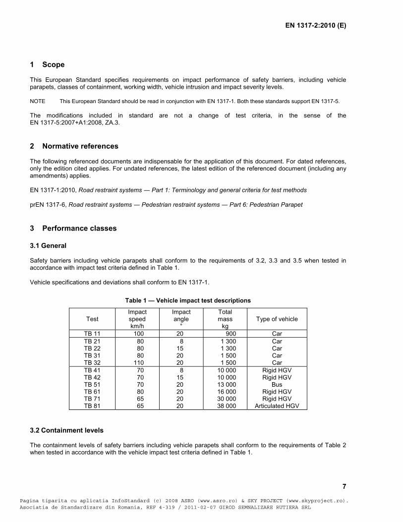
This European Standard specifies requirements on impact performance of safety barriers, including vehicle parapets, classes of containment, working width, vehicle intrusion and impact severity levels.
NOTE This European Standard should be read in conjunction with EN 1317-1. Both these standards support EN 1317-5.
The modifications included in standard are not a change of test criteria, in the sense of the EN 1317-5:2007+A1:2008, ZA.3.
2 Normative references
The following referenced documents are indispensable for the application of this document. For dated references, only the edition cited applies. For undated references, the latest edition of the referenced document (including any amendments) applies.
EN 1317-1:2010, Road restraint systems Part 1: Terminology and general criteria for test methods
prEN 1317-6, Road restraint systems Pedestrian restraint systems Part 6: Pedestrian Parapet
3 Performance classes
3.1 General
Safety barriers including vehicle parapets shall conform to the requirements of 3.2, 3.3 and 3.5 when tested in accordance with impact test criteria defined in Table 1.
Vehicle specifications and deviations shall conform to EN 1317-1.
Table 1 — Vehicle impact test descriptions
Test Impact speed km/h
Impact angle
°
Total mass
kg Type of vehicle
TB 11 100 20 900 Car TB 21 TB 22 TB 31 TB 32
80 80 80 110
8 15 20 20
1 300 1 300 1 500 1 500
Car Car Car Car
TB 41 TB 42 TB 51 TB 61 TB 71 TB 81
70 70 70 80 65 65
8 15 20 20 20 20
10 000 10 000 13 000 16 000 30 000 38 000
Rigid HGV Rigid HGV
Bus Rigid HGV Rigid HGV
Articulated HGV
3.2 Containment levels
The containment levels of safety barriers including vehicle parapets shall conform to the requirements of Table 2 when tested in accordance with the vehicle impact test criteria defined in Table 1.
Pagina tiparita cu aplicatia InfoStandard (c) 2008 ASRO (www.asro.ro) & SKY PROJECT (www.skyproject.ro).Asociatia de Standardizare din Romania, REF 4-319 / 2011-02-07 GIROD SEMNALIZARE RUTIERA SRL

EN 1317-2:2010 (E)
8
Table 2 — Containment levels
Containment levels Acceptance test
Low angle containment T1
TB 21
T2
TB 22
T3
TB 41 and TB 21
Normal containment N1
TB 31
N2 TB 32 and TB 11
Higher containment H1
TB 42 and TB 11
L1 TB 42 and TB32 and TB 11
H2 TB 51 and TB 11
L2 TB 51 and TB32 and TB 11
H3 TB 61 and TB 11
L3 TB 61 and TB32 and TB 11
Very high containment H4a H4b TB 71 and TB 11
TB 81 and TB 11
L4a L4b
TB 71 and TB32 and TB 11 TB 81 and TB32 and TB 11
NOTE 1 Low angle containment levels are intended to be used only for temporary safety barriers. Temporary safety barriers can also be tested for higher levels of containment.
NOTE 2 A successfully tested barrier at a given containment level should be considered as having met the containment requirements of any lower level, except that N1 and N2 do not include T3, H-Levels do not include L-Levels and that H1, ..., H4b do not include N2.
NOTE 3 Because testing and development for very high containment safety barriers in different countries has taken place using significantly different types of heavy vehicles, both tests TB 71 and TB 81 are included in the standard at present. The two containment levels H4a and H4b should not be regarded as equivalent and no hierarchy is given between them. The same holds for the two containment levels L4a and L4b.
NOTE 4 The performance of Containment Classes L is enhanced in respect to the corresponding H classes by the addition of Test TB 32.
The evaluation of a vehicle restraint system within the range of containment levels T3, N2, H1, H2, H3, H4a, H4b, L1, L2, L3, L4a and L4b shall require the carrying out of different tests:
a) A test according to the maximum level of containment for that particular system; and
Pagina tiparita cu aplicatia InfoStandard (c) 2008 ASRO (www.asro.ro) & SKY PROJECT (www.skyproject.ro).Asociatia de Standardizare din Romania, REF 4-319 / 2011-02-07 GIROD SEMNALIZARE RUTIERA SRL
EN 1317-2:2010 (E)
9
b) Test(s) using cars in order to verify that satisfactory containment of the maximum level is also compatible with safety for a range of cars.
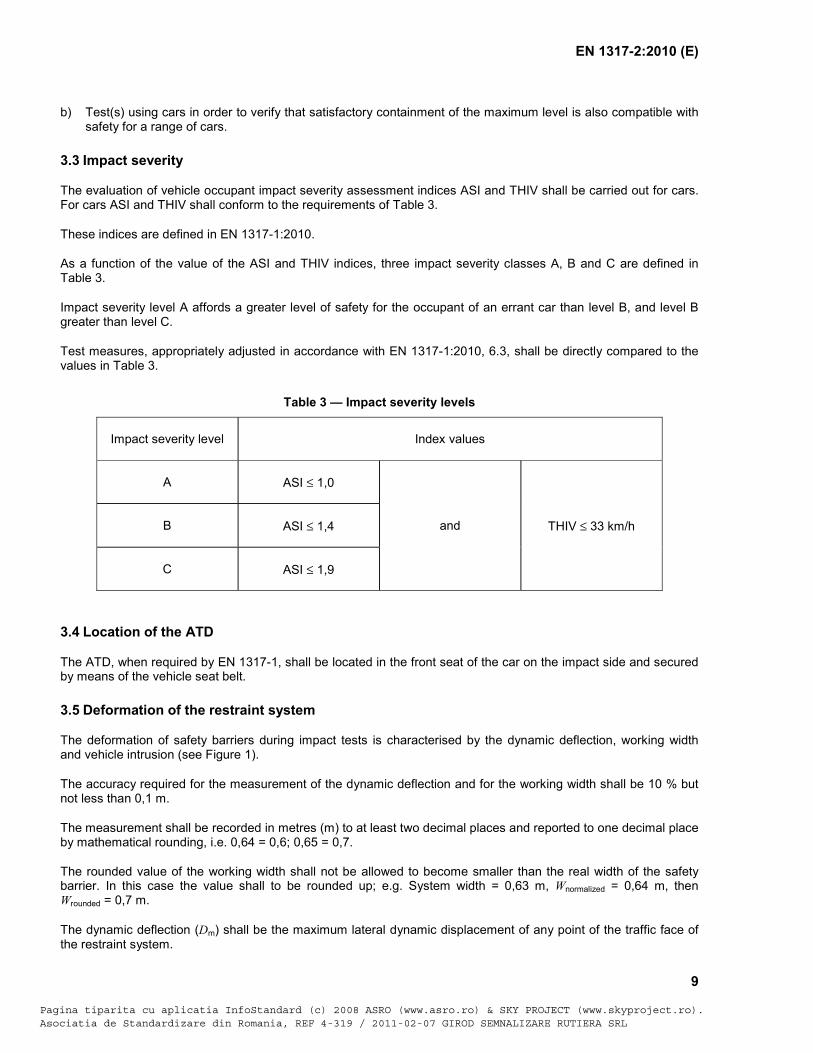
3.3 Impact severity
The evaluation of vehicle occupant impact severity assessment indices ASI and THIV shall be carried out for cars. For cars ASI and THIV shall conform to the requirements of Table 3.
These indices are defined in EN 1317-1:2010.
As a function of the value of the ASI and THIV indices, three impact severity classes A, B and C are defined in Table 3.
Impact severity level A affords a greater level of safety for the occupant of an errant car than level B, and level B greater than level C.
Test measures, appropriately adjusted in accordance with EN 1317-1:2010, 6.3, shall be directly compared to the values in Table 3.
Table 3 — Impact severity levels
Impact severity level Index values
A ASI ≤ 1,0
and THIV ≤ 33 km/h B ASI ≤ 1,4
C ASI ≤ 1,9
3.4 Location of the ATD
The ATD, when required by EN 1317-1, shall be located in the front seat of the car on the impact side and secured by means of the vehicle seat belt.
3.5 Deformation of the restraint system
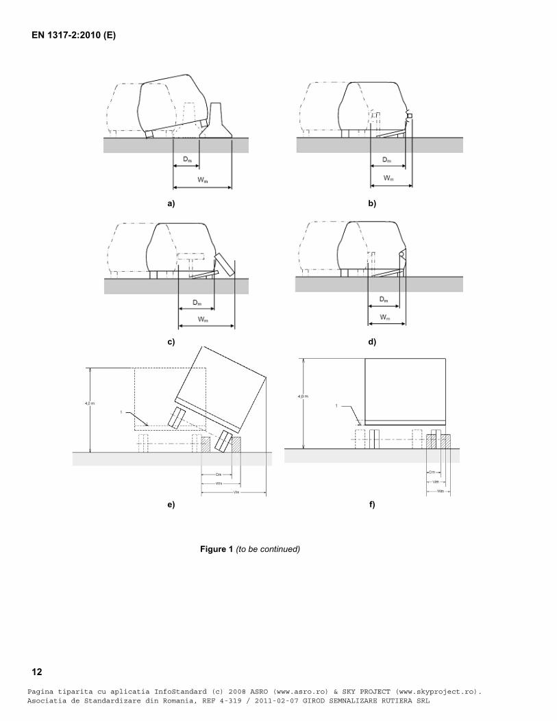
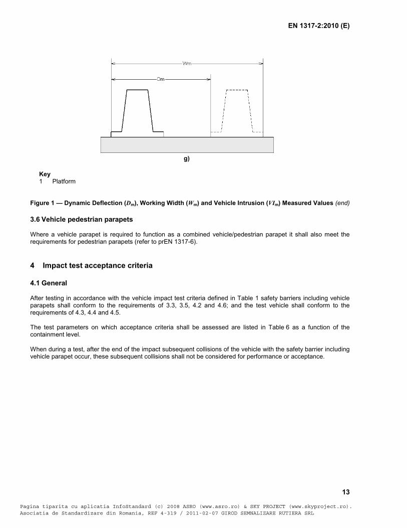
The deformation of safety barriers during impact tests is characterised by the dynamic deflection, working width and vehicle intrusion (see Figure 1).
The accuracy required for the measurement of the dynamic deflection and for the working width shall be 10 % but not less than 0,1 m.
The measurement shall be recorded in metres (m) to at least two decimal places and reported to one decimal place by mathematical rounding, i.e. 0,64 = 0,6; 0,65 = 0,7.
The rounded value of the working width shall not be allowed to become smaller than the real width of the safety barrier. In this case the value shall to be rounded up; e.g. System width = 0,63 m, Wnormalized = 0,64 m, then Wrounded = 0,7 m.
The dynamic deflection (Dm) shall be the maximum lateral dynamic displacement of any point of the traffic face of the restraint system.
Pagina tiparita cu aplicatia InfoStandard (c) 2008 ASRO (www.asro.ro) & SKY PROJECT (www.skyproject.ro).Asociatia de Standardizare din Romania, REF 4-319 / 2011-02-07 GIROD SEMNALIZARE RUTIERA SRL
EN 1317-2:2010 (E)
10
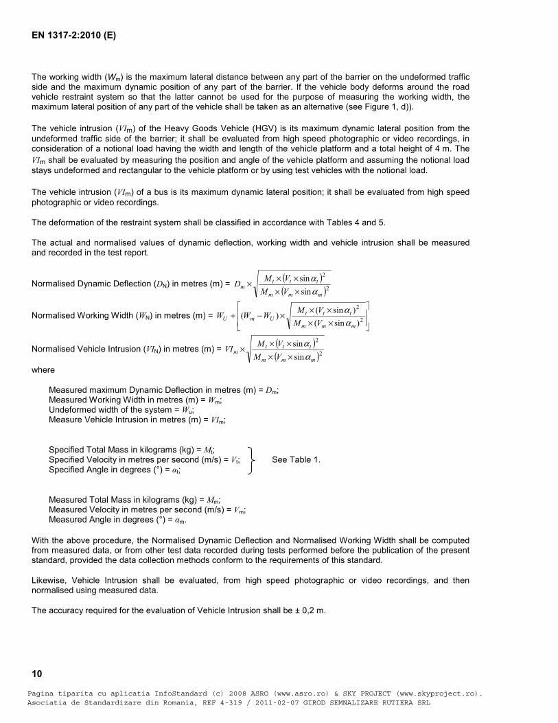
The working width (Wm) is the maximum lateral distance between any part of the barrier on the undeformed traffic side and the maximum dynamic position of any part of the barrier. If the vehicle body deforms around the road vehicle restraint system so that the latter cannot be used for the purpose of measuring the working width, the maximum lateral position of any part of the vehicle shall be taken as an alternative (see Figure 1, d)).
The vehicle intrusion (VIm) of the Heavy Goods Vehicle (HGV) is its maximum dynamic lateral position from the undeformed traffic side of the barrier; it shall be evaluated from high speed photographic or video recordings, in consideration of a notional load having the width and length of the vehicle platform and a total height of 4 m. The VIm shall be evaluated by measuring the position and angle of the vehicle platform and assuming the notional load stays undeformed and rectangular to the vehicle platform or by using test vehicles with the notional load.
The vehicle intrusion (VIm) of a bus is its maximum dynamic lateral position; it shall be evaluated from high speed photographic or video recordings.
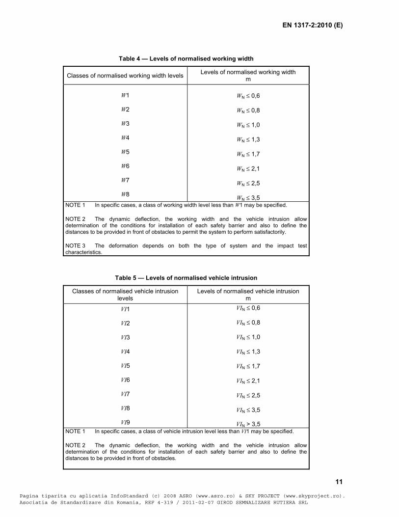
The deformation of the restraint system shall be classified in accordance with Tables 4 and 5.
The actual and normalised values of dynamic deflection, working width and vehicle intrusion shall be measured and recorded in the test report.
Normalised Dynamic Deflection (DN) in metres (m) = ( )( )2
2
sinsin
mmm
tttm VM
VMDαα
×××××
Normalised Working Width (WN) in metres (m) = ×××××−+ 2
2
)sin()sin()(mmm
tttUmU VM
VMWWWαα
Normalised Vehicle Intrusion (VIN) in metres (m) = ( )( )2
2
sinsin
mmm
tttm VM
VMVIαα
×××××
where
Measured maximum Dynamic Deflection in metres (m) = Dm; Measured Working Width in metres (m) = Wm; Undeformed width of the system = Wu; Measure Vehicle Intrusion in metres (m) = VIm;
Specified Total Mass in kilograms (kg) = Mt; Specified Velocity in metres per second (m/s) = Vt; See Table 1. Specified Angle in degrees (°) = t;
Measured Total Mass in kilograms (kg) = Mm; Measured Velocity in metres per second (m/s) = Vm; Measured Angle in degrees (°) = m.
With the above procedure, the Normalised Dynamic Deflection and Normalised Working Width shall be computed from measured data, or from other test data recorded during tests performed before the publication of the present standard, provided the data collection methods conform to the requirements of this standard.
Likewise, Vehicle Intrusion shall be evaluated, from high speed photographic or video recordings, and then normalised using measured data.
The accuracy required for the evaluation of Vehicle Intrusion shall be ± 0,2 m.
Pagina tiparita cu aplicatia InfoStandard (c) 2008 ASRO (www.asro.ro) & SKY PROJECT (www.skyproject.ro).Asociatia de Standardizare din Romania, REF 4-319 / 2011-02-07 GIROD SEMNALIZARE RUTIERA SRL
EN 1317-2:2010 (E)
11
Table 4 — Levels of normalised working width
Classes of normalised working width levels Levels of normalised working width m
W1
W2
W3
W4
W5
W6
W7
W8
WN ≤ 0,6
WN ≤ 0,8
WN ≤ 1,0
WN ≤ 1,3
WN ≤ 1,7
WN ≤ 2,1
WN ≤ 2,5
WN ≤ 3,5
NOTE 1 In specific cases, a class of working width level less than W1 may be specified.
NOTE 2 The dynamic deflection, the working width and the vehicle intrusion allow determination of the conditions for installation of each safety barrier and also to define the distances to be provided in front of obstacles to permit the system to perform satisfactorily.
NOTE 3 The deformation depends on both the type of system and the impact test characteristics.
Table 5 — Levels of normalised vehicle intrusion
Classes of normalised vehicle intrusion levels
Levels of normalised vehicle intrusion m
VI1 VI2
VI3
VI4
VI5
VI6
VI7
VI8
VI9
VIN ≤ 0,6
VIN ≤ 0,8
VIN ≤ 1,0
VIN ≤ 1,3
VIN ≤ 1,7
VIN ≤ 2,1
VIN ≤ 2,5
VIN ≤ 3,5
VIN > 3,5 NOTE 1 In specific cases, a class of vehicle intrusion level less than VI1 may be specified.
NOTE 2 The dynamic deflection, the working width and the vehicle intrusion allow determination of the conditions for installation of each safety barrier and also to define the distances to be provided in front of obstacles.
Pagina tiparita cu aplicatia InfoStandard (c) 2008 ASRO (www.asro.ro) & SKY PROJECT (www.skyproject.ro).Asociatia de Standardizare din Romania, REF 4-319 / 2011-02-07 GIROD SEMNALIZARE RUTIERA SRL
EN 1317-2:2010 (E)
12
Figure 1 (to be continued)
a) b)
c) d)
e) f)
Pagina tiparita cu aplicatia InfoStandard (c) 2008 ASRO (www.asro.ro) & SKY PROJECT (www.skyproject.ro).Asociatia de Standardizare din Romania, REF 4-319 / 2011-02-07 GIROD SEMNALIZARE RUTIERA SRL
EN 1317-2:2010 (E)
13
Key 1 Platform
Figure 1 — Dynamic Deflection (Dm), Working Width (Wm) and Vehicle Intrusion (VIm) Measured Values (end)
3.6 Vehicle pedestrian parapets
Where a vehicle parapet is required to function as a combined vehicle/pedestrian parapet it shall also meet the requirements for pedestrian parapets (refer to prEN 1317-6).
4 Impact test acceptance criteria
4.1 General
After testing in accordance with the vehicle impact test criteria defined in Table 1 safety barriers including vehicle parapets shall conform to the requirements of 3.3, 3.5, 4.2 and 4.6; and the test vehicle shall conform to the requirements of 4.3, 4.4 and 4.5.
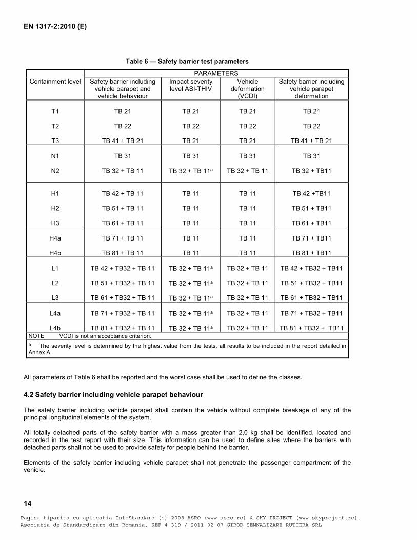
The test parameters on which acceptance criteria shall be assessed are listed in Table 6 as a function of the containment level.
When during a test, after the end of the impact subsequent collisions of the vehicle with the safety barrier including vehicle parapet occur, these subsequent collisions shall not be considered for performance or acceptance.
g)
Pagina tiparita cu aplicatia InfoStandard (c) 2008 ASRO (www.asro.ro) & SKY PROJECT (www.skyproject.ro).Asociatia de Standardizare din Romania, REF 4-319 / 2011-02-07 GIROD SEMNALIZARE RUTIERA SRL
EN 1317-2:2010 (E)
14
Table 6 — Safety barrier test parameters
PARAMETERS Containment level Safety barrier including
vehicle parapet and vehicle behaviour
Impact severity level ASI-THIV
Vehicle deformation
(VCDI)
Safety barrier including vehicle parapet
deformation
T1
T2
T3
TB 21
TB 22
TB 41 + TB 21
TB 21
TB 22
TB 21
TB 21
TB 22
TB 21
TB 21
TB 22
TB 41 + TB 21
N1
N2
TB 31
TB 32 + TB 11
TB 31
TB 32 + TB 11a
TB 31
TB 32 + TB 11
TB 31
TB 32 + TB11
H1
H2
H3
TB 42 + TB 11
TB 51 + TB 11
TB 61 + TB 11
TB 11
TB 11
TB 11
TB 11
TB 11
TB 11
TB 42 +TB11
TB 51 + TB11
TB 61 + TB11
H4a
H4b
TB 71 + TB 11
TB 81 + TB 11
TB 11
TB 11
TB 11
TB 11
TB 71 + TB11
TB 81 + TB11
L1
L2
L3
TB 42 + TB32 + TB 11
TB 51 + TB32 + TB 11
TB 61 + TB32 + TB 11
TB 32 + TB 11a
TB 32 + TB 11a
TB 32 + TB 11a
TB 32 + TB 11
TB 32 + TB 11
TB 32 + TB 11
TB 42 + TB32 + TB11
TB 51 + TB32 + TB11
TB 61 + TB32 + TB11
L4a
L4b
TB 71 + TB32 + TB 11
TB 81 + TB32 + TB 11
TB 32 + TB 11a
TB 32 + TB 11a
TB 32 + TB 11
TB 32 + TB 11
TB 71 + TB32 + TB11
TB 81 + TB32 + TB11
NOTE VCDI is not an acceptance criterion. a
The severity level is determined by the highest value from the tests, all results to be included in the report detailed in Annex A.
All parameters of Table 6 shall be reported and the worst case shall be used to define the classes.
4.2 Safety barrier including vehicle parapet behaviour
The safety barrier including vehicle parapet shall contain the vehicle without complete breakage of any of the principal longitudinal elements of the system.
All totally detached parts of the safety barrier with a mass greater than 2,0 kg shall be identified, located and recorded in the test report with their size. This information can be used to define sites where the barriers with detached parts shall not be used to provide safety for people behind the barrier.
Elements of the safety barrier including vehicle parapet shall not penetrate the passenger compartment of the vehicle.
Pagina tiparita cu aplicatia InfoStandard (c) 2008 ASRO (www.asro.ro) & SKY PROJECT (www.skyproject.ro).Asociatia de Standardizare din Romania, REF 4-319 / 2011-02-07 GIROD SEMNALIZARE RUTIERA SRL
EN 1317-2:2010 (E)
15
Deformations of, or intrusions into the passenger compartment that can cause serious injuries shall not be permitted.
Foundations, ground anchorages and fixings shall perform according to the design of the safety barrier including vehicle parapets.
NOTE The performance of barriers including vehicle parapets may be strongly influenced by the behaviour of their foundations, anchorages and fixing. If anchorages are embedded in soil, the test item should be installed in a soil corresponding to the specifications in the design of the barrier. If the barrier is designed to be installed on a bridge or on a retaining wall, the bearing capability of the supporting surface and the strength of the anchorages should be not less than the design requirements.
4.3 Test vehicle behaviour
During and after the impact, no more than one of the wheels of the vehicle shall completely pass over or under the safety barrier.
The vehicle shall not roll over (including rollover of the vehicle onto its side) during or after impact.
For tests with HGVs and buses, not more than 5 % of the mass of the ballast shall become detached or be spilt during the test up to the time when the wheel tracks of the vehicle leaves the exit box.
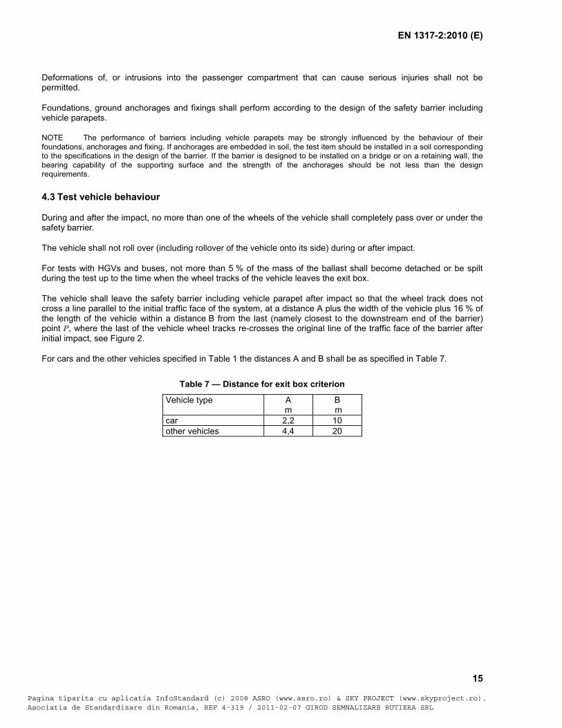
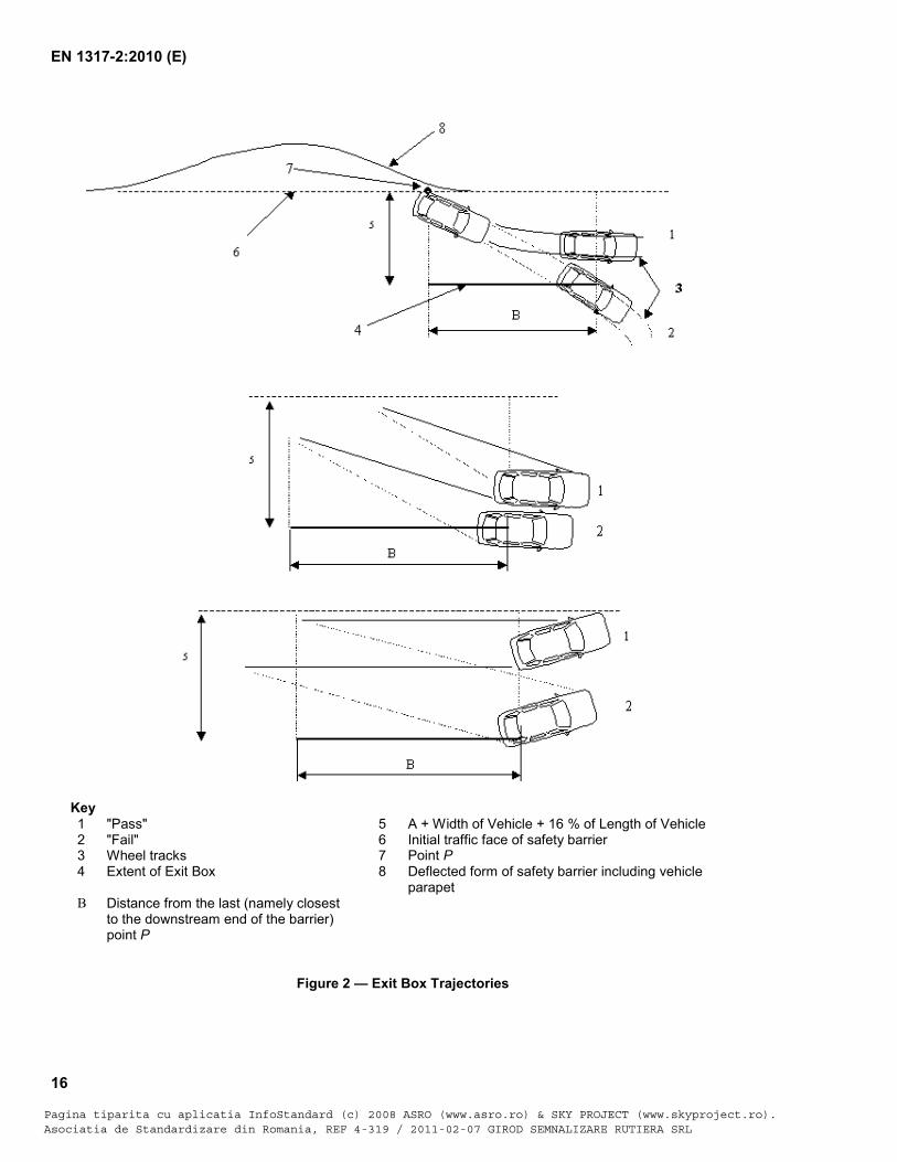
The vehicle shall leave the safety barrier including vehicle parapet after impact so that the wheel track does not cross a line parallel to the initial traffic face of the system, at a distance A plus the width of the vehicle plus 16 % of the length of the vehicle within a distance B from the last (namely closest to the downstream end of the barrier) point P, where the last of the vehicle wheel tracks re-crosses the original line of the traffic face of the barrier after initial impact, see Figure 2.
For cars and the other vehicles specified in Table 1 the distances A and B shall be as specified in Table 7.
Table 7 — Distance for exit box criterion
Vehicle type A m
B m
car 2,2 10 other vehicles 4,4 20
Pagina tiparita cu aplicatia InfoStandard (c) 2008 ASRO (www.asro.ro) & SKY PROJECT (www.skyproject.ro).Asociatia de Standardizare din Romania, REF 4-319 / 2011-02-07 GIROD SEMNALIZARE RUTIERA SRL
EN 1317-2:2010 (E)
16
Key 1 "Pass" 5 A + Width of Vehicle + 16 % of Length of Vehicle 2 "Fail" 6 Initial traffic face of safety barrier 3 Wheel tracks 7 Point P 4 Extent of Exit Box 8 Deflected form of safety barrier including vehicle
parapet B Distance from the last (namely closest
to the downstream end of the barrier) point P
Figure 2 — Exit Box Trajectories
Pagina tiparita cu aplicatia InfoStandard (c) 2008 ASRO (www.asro.ro) & SKY PROJECT (www.skyproject.ro).Asociatia de Standardizare din Romania, REF 4-319 / 2011-02-07 GIROD SEMNALIZARE RUTIERA SRL
EN 1317-2:2010 (E)
17
4.4 Severity Index
The severity index ASI and THIV shall be computed using the vehicle instrumentation as specified in EN 1317-1. These values shall be quoted in the test report.
Severity indices shall be reported for all tests with cars.
4.5 Test vehicle deformation
The deformation of the interior of the vehicle shall be evaluated and recorded in the form of VCDI (Vehicle Cockpit Deformation Index) in all tests with cars as described in EN 1317-1.
4.6 Safety barrier deformation
The measured and normalised values for dynamic deflection and for the working width shall be determined and the levels quoted in the test report detailed in Annex A. Vehicle intrusion shall also be quoted in the test report for tests involving HGVs and buses.
4.7 Tests for system type tested safety barriers (Families of barriers)
A family of barriers can be derived from a single parent barrier. The parent barrier shall fulfil the requirements of a containment level. The parent barrier shall be the lowest working width member to define the upper containment level, and the highest severity level, for the family of barriers. A family of barriers might cover various containment levels and/or working width. The purpose of family of barriers is to avoid subsequent TB32 (for L1 to L4b), TB11 or TB21 (for T3 only) tests. Each barrier of the family shall be tested at least once with the heaviest vehicle in the containment class. This defines the containment and working width classes for the family member.
The severity level for each family member shall be defined by the parent barrier test.
The family of barriers shall be only relevant to the following three cases:
a) For barriers with single or multiple identically cross sectioned longitudinal elements, with a different spacing of posts or intermediate ground fixations;
b) For the case of a free-standing barrier, differing only in their unit length;
c) Barriers with additional height and additional parts, where the parts in contact with the vehicle during the TB11 test do not differ.
The family of barriers:
d) are assembled from the same components, excluding extra parts;
e) have the same family name;
f) have the same working mechanism for the system and for the components.
All other cases shall be treated as modified products.
5 Test methods
5.1 Test site
Test site shall be according to EN 1317-1:2010, 5.1.
Pagina tiparita cu aplicatia InfoStandard (c) 2008 ASRO (www.asro.ro) & SKY PROJECT (www.skyproject.ro).Asociatia de Standardizare din Romania, REF 4-319 / 2011-02-07 GIROD SEMNALIZARE RUTIERA SRL
EN 1317-2:2010 (E)
18
5.2 Test vehicles
Test vehicles shall be according to EN 1317-1:2010, 5.2.
5.3 Safety barrier
5.3.1 General
Detailed descriptions and design specifications of the test item shall be included in the test report to enable verification of conformity of the installed system to be tested.
The design specification shall include reference to foundation performance requirements, and where the product is a vehicle parapet, the design specification shall include reference to the anchor/ground fixing.
5.3.2 Installation
The length of the safety barrier or vehicle parapet tested shall be sufficient to demonstrate the full performance characteristic of any longer installation. After the test the adequacy of the length of installation shall be checked by procedure as the one in Annex B. The test lengths shall be defined by the manufacturer prior to the test so that the car test(s) demonstrates the maximum severity of impact, and the large vehicle test demonstrates the maximum dynamic deflection characteristics.
End conditions (for example end anchorage) shall be provided in accordance with the safety barrier including vehicle parapet specification and defined by the manufacturer. If an end anchorage is used which is specifically for testing and not part of the design of the system being tested, this end anchorage shall be fully described in the test report. Any end anchorage should not restrict the maximum lateral deflection of the safety barrier.
Foundations shall meet the design specification.
When testing pretensioned systems, where tension can be adjusted (for example cable barriers), the small vehicle test shall be performed with a tension corresponding to a temperature of - 10 °C and the large vehicle test with a tension corresponding to a temperature of + 30 °C. For the containment levels with only one test, the tension shall correspond to a temperature of 0 °C. The data for the recommended tensions/temperature shall be supplied by the manufacturer.
Where a vehicle parapet is required to have infilling or other modification in order that it may function as a vehicle pedestrian parapet, this infilling or other modification shall be included in the test installation if it will affect the performance of the vehicle parapet.
5.3.3 Position of the impact point
The impact point shall be chosen by the test house and shall demonstrate the worst-case testing conditions of the safety barrier including vehicle parapet, and shall include any sensitive feature of the design. If the test house chooses an impact point other than that at a point about one third of the installation length, in order to ensure worst-case conditions, then this choice shall be justified in the test report.
5.4 Accuracies and limit deviations of impact speeds and approach angle
5.4.1 Vehicle impact speed
Vehicle impact speed shall be measured along the vehicle approach path no further than 6 m before the impact point. The overall accuracy of speed measurement shall be within ± 1 %.
The impact speed limit deviation shall be: %0
%7+.
Pagina tiparita cu aplicatia InfoStandard (c) 2008 ASRO (www.asro.ro) & SKY PROJECT (www.skyproject.ro).Asociatia de Standardizare din Romania, REF 4-319 / 2011-02-07 GIROD SEMNALIZARE RUTIERA SRL

EN 1317-2:2010 (E)
19
5.4.2 Vehicle approach angle
Vehicle approach angle shall be measured along the vehicle approach path no further than 6 m before the impact point. The overall accuracy shall be within ± 0,5°.
The impact angle limit deviation shall be: °−°+
0,15,1
.
5.4.3 Combined limit deviation of speed and angle
To avoid large differences of impact energy, the maximum limit deviation for speed and angle shall not be combined.
At the upper angle tolerance of + 1,5° the upper speed limit deviation is reduced to + 5 %, and at the angle limit deviation of - 1,0° the lower speed limit deviation is increased to + 2 %.
The complete combined tolerance envelope shall be shown in Figure 3.
Key A Angle B Speed
Figure 3 — Envelope of combined tolerances
The given limit deviations only serve to take account of different test installations or test procedures and are not intended to provide a spectrum from which the energy of the test can be chosen.
In any case, the nominal values of Table 1 shall serve as a basis.
5.5 Vehicle instrumentation
Vehicle instrumentation shall be according to EN 1317-1:2010, Clause 6.
A
B
Pagina tiparita cu aplicatia InfoStandard (c) 2008 ASRO (www.asro.ro) & SKY PROJECT (www.skyproject.ro).Asociatia de Standardizare din Romania, REF 4-319 / 2011-02-07 GIROD SEMNALIZARE RUTIERA SRL
EN 1317-2:2010 (E)
20
5.6 Photographic coverage
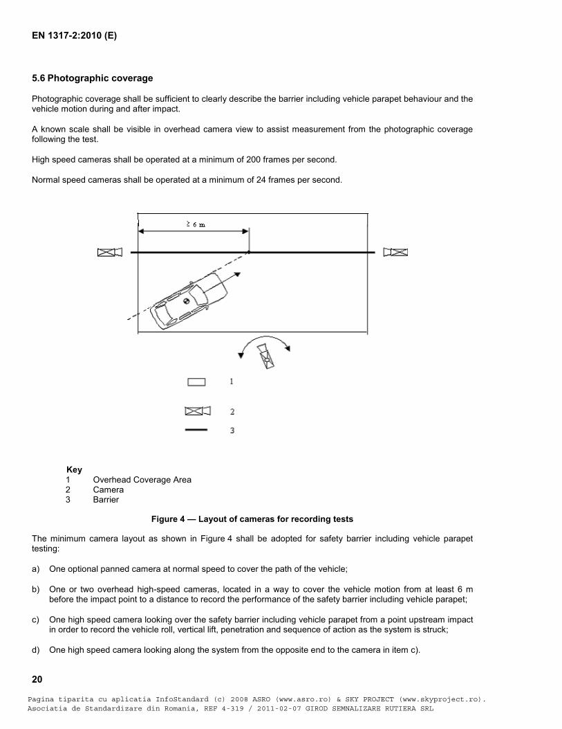
Photographic coverage shall be sufficient to clearly describe the barrier including vehicle parapet behaviour and the vehicle motion during and after impact.
A known scale shall be visible in overhead camera view to assist measurement from the photographic coverage following the test.
High speed cameras shall be operated at a minimum of 200 frames per second.
Normal speed cameras shall be operated at a minimum of 24 frames per second.
Key
1 Overhead Coverage Area 2 Camera 3 Barrier
Figure 4 — Layout of cameras for recording tests
The minimum camera layout as shown in Figure 4 shall be adopted for safety barrier including vehicle parapet testing:
a) One optional panned camera at normal speed to cover the path of the vehicle;
b) One or two overhead high-speed cameras, located in a way to cover the vehicle motion from at least 6 m before the impact point to a distance to record the performance of the safety barrier including vehicle parapet;
c) One high speed camera looking over the safety barrier including vehicle parapet from a point upstream impact in order to record the vehicle roll, vertical lift, penetration and sequence of action as the system is struck;
d) One high speed camera looking along the system from the opposite end to the camera in item c).
Pagina tiparita cu aplicatia InfoStandard (c) 2008 ASRO (www.asro.ro) & SKY PROJECT (www.skyproject.ro).Asociatia de Standardizare din Romania, REF 4-319 / 2011-02-07 GIROD SEMNALIZARE RUTIERA SRL
EN 1317-2:2010 (E)
21
NOTE The need for additional cameras should be considered to cover areas of special interest.
6 Test report
The test report shall be comply with Annex A.
Pagina tiparita cu aplicatia InfoStandard (c) 2008 ASRO (www.asro.ro) & SKY PROJECT (www.skyproject.ro).Asociatia de Standardizare din Romania, REF 4-319 / 2011-02-07 GIROD SEMNALIZARE RUTIERA SRL
EN 1317-2:2010 (E)
22
Annex A (normative)
Detailed Test Report Template
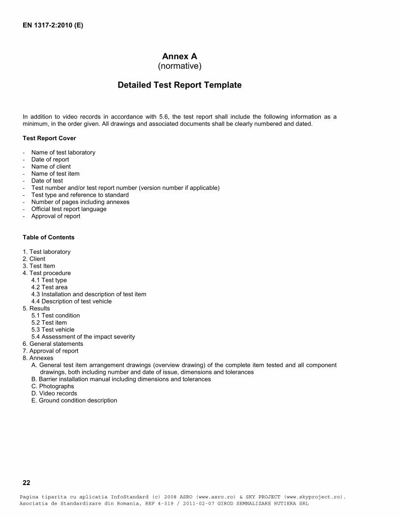
In addition to video records in accordance with 5.6, the test report shall include the following information as a minimum, in the order given. All drawings and associated documents shall be clearly numbered and dated.
Test Report Cover - Name of test laboratory - Date of report - Name of client - Name of test item - Date of test - Test number and/or test report number (version number if applicable) - Test type and reference to standard - Number of pages including annexes - Official test report language - Approval of report Table of Contents
1. Test laboratory 2. Client 3. Test Item 4. Test procedure
4.1 Test type 4.2 Test area 4.3 Installation and description of test item 4.4 Description of test vehicle
5. Results 5.1 Test condition 5.2 Test item 5.3 Test vehicle 5.4 Assessment of the impact severity
6. General statements 7. Approval of report 8. Annexes
A. General test item arrangement drawings (overview drawing) of the complete item tested and all component drawings, both including number and date of issue, dimensions and tolerances
B. Barrier installation manual including dimensions and tolerances C. Photographs D. Video records E. Ground condition description
Pagina tiparita cu aplicatia InfoStandard (c) 2008 ASRO (www.asro.ro) & SKY PROJECT (www.skyproject.ro).Asociatia de Standardizare din Romania, REF 4-319 / 2011-02-07 GIROD SEMNALIZARE RUTIERA SRL
EN 1317-2:2010 (E)
23
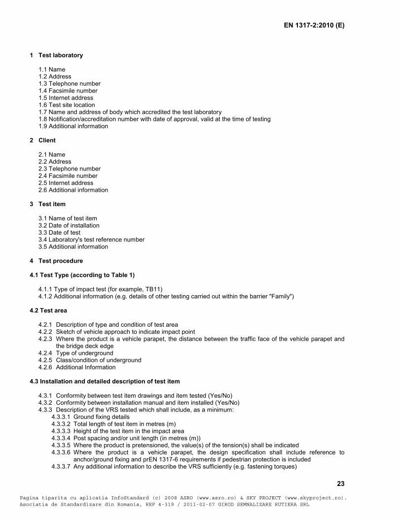
1 Test laboratory 1.1 Name 1.2 Address 1.3 Telephone number 1.4 Facsimile number 1.5 Internet address 1.6 Test site location 1.7 Name and address of body which accredited the test laboratory 1.8 Notification/accreditation number with date of approval, valid at the time of testing 1.9 Additional information
2 Client 2.1 Name 2.2 Address 2.3 Telephone number 2.4 Facsimile number 2.5 Internet address 2.6 Additional information
3 Test item 3.1 Name of test item 3.2 Date of installation 3.3 Date of test 3.4 Laboratory's test reference number 3.5 Additional information
4 Test procedure
4.1 Test Type (according to Table 1)
4.1.1 Type of impact test (for example, TB11)
4.1.2 Additional information (e.g. details of other testing carried out within the barrier "Family")
4.2 Test area
4.2.1 Description of type and condition of test area 4.2.2 Sketch of vehicle approach to indicate impact point 4.2.3 Where the product is a vehicle parapet, the distance between the traffic face of the vehicle parapet and
the bridge deck edge 4.2.4 Type of underground 4.2.5 Class/condition of underground 4.2.6 Additional Information
4.3 Installation and detailed description of test item
4.3.1 Conformity between test item drawings and item tested (Yes/No) 4.3.2 Conformity between installation manual and item installed (Yes/No) 4.3.3 Description of the VRS tested which shall include, as a minimum:
4.3.3.1 Ground fixing details 4.3.3.2 Total length of test item in metres (m) 4.3.3.3 Height of the test item in the impact area 4.3.3.4 Post spacing and/or unit length (in metres (m)) 4.3.3.5 Where the product is pretensioned, the value(s) of the tension(s) shall be indicated 4.3.3.6 Where the product is a vehicle parapet, the design specification shall include reference to
anchor/ground fixing and prEN 1317-6 requirements if pedestrian protection is included 4.3.3.7 Any additional information to describe the VRS sufficiently (e.g. fastening torques)
Pagina tiparita cu aplicatia InfoStandard (c) 2008 ASRO (www.asro.ro) & SKY PROJECT (www.skyproject.ro).Asociatia de Standardizare din Romania, REF 4-319 / 2011-02-07 GIROD SEMNALIZARE RUTIERA SRL
EN 1317-2:2010 (E)
24
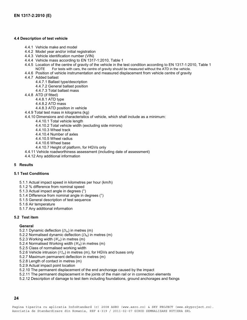
4.4 Description of test vehicle
4.4.1 Vehicle make and model 4.4.2 Model year and/or initial registration 4.4.3 Vehicle identification number (VIN) 4.4.4 Vehicle mass according to EN 1317-1:2010, Table 1 4.4.5 Location of the centre of gravity of the vehicle in the test condition according to EN 1317-1:2010, Table 1
NOTE For tests with cars, the centre of gravity should be measured without the ATD in the vehicle. 4.4.6 Position of vehicle instrumentation and measured displacement from vehicle centre of gravity 4.4.7 Added ballast
4.4.7.1 Ballast type/description 4.4.7.2 General ballast position 4.4.7.3 Total ballast mass
4.4.8 ATD (if fitted) 4.4.8.1 ATD type 4.4.8.2 ATD mass 4.4.8.3 ATD position in vehicle
4.4.9 Total test mass in kilograms (kg) 4.4.10 Dimensions and characteristics of vehicle, which shall include as a minimum:
4.4.10.1 Total vehicle length 4.4.10.2 Total vehicle width (excluding side mirrors) 4.4.10.3 Wheel track 4.4.10.4 Number of axles 4.4.10.5 Wheel radius 4.4.10.6 Wheel base 4.4.10.7 Height of platform, for HGVs only
4.4.11 Vehicle roadworthiness assessment (including date of assessment) 4.4.12 Any additional information
5 Results 5.1 Test Conditions
5.1.1 Actual impact speed in kilometres per hour (km/h) 5.1.2 % difference from nominal speed 5.1.3 Actual impact angle in degrees (°) 5.1.4 Difference from nominal angle in degrees (°) 5.1.5 General description of test sequence 5.1.6 Air temperature 5.1.7 Any additional information
5.2 Test item
General 5.2.1 Dynamic deflection (Dm) in metres (m) 5.2.2 Normalised dynamic deflection (DN) in metres (m) 5.2.3 Working width (Wm) in metres (m) 5.2.4 Normalised Working width (WN) in metres (m) 5.2.5 Class of normalised working width 5.2.6 Vehicle intrusion (VIm) in metres (m), for HGVs and buses only 5.2.7 Maximum permanent deflection in metres (m) 5.2.8 Length of contact in metres (m) 5.2.9 Actual impact point location 5.2.10 The permanent displacement of the end anchorage caused by the impact 5.2.11 The permanent displacement in the joints of the main rail or in connection elements 5.2.12 Description of damage to test item including foundations, ground anchorages and fixings
Pagina tiparita cu aplicatia InfoStandard (c) 2008 ASRO (www.asro.ro) & SKY PROJECT (www.skyproject.ro).Asociatia de Standardizare din Romania, REF 4-319 / 2011-02-07 GIROD SEMNALIZARE RUTIERA SRL
EN 1317-2:2010 (E)
25
NOTE Optional: For vehicle restraint systems to be mounted on bridges, retaining walls, or on other structures, the time history of the forces and moments on the fixings or other critical points during the impact may also be recorded.
Impact test acceptance criteria 5.2.13 Safety barrier including vehicle parapet contained the test vehicle (Yes/No) – if no, description is required. 5.2.14 Complete breakage of any principal longitudinal elements of the test item (Yes/No) – if yes, description is required. 5.2.15 Details of test item parts over the mass of 2 kg totally detached:
5.2.15.1 Identification 5.2.15.2 Mass in kilograms (kg) 5.2.15.3 Final location measured perpendicular to the original traffic face of the barrier 5.2.15.4 Final location measured along the line of the original traffic face of the barrier starting from the detachment point
5.2.16 Elements of the safety barrier including vehicle parapet penetrated the passenger compartment of the vehicle (Yes/No) – if yes, description of penetration is required. 5.2.17 Deformations of and/or intrusions into the passenger compartment (Yes/No) – if yes, description of deformations and/or intrusions are required.
5.3 Test vehicle
General 5.3.1 General description of vehicle trajectory 5.3.2 Vehicle cockpit deformation index VCDI (required for cars) 5.3.3 Description of the damage and deformation to the test vehicle 5.3.4 Description of any contact of the dummy head with part of the barrier Impact test acceptance criteria 5.3.4 Actual impact speed and angle within tolerance limits? (Yes/No) 5.3.5 Actual impact speed and angle combination within the tolerance envelope in Figure 3 (Yes/No) 5.3.6 During and after the impact, no more than one wheel of the vehicle passes over the rearmost part of the
deformed system (Yes/No) 5.3.7 Vehicle rolls over during the test (Yes/No) 5.3.8 For tests with HGVs, more than 5 % of the mass of the ballast becomes detached or spilt during the test
up to the time when the vehicle comes to rest (Yes/No) – if yes, record %. 5.3.9 Vehicle within "exit box" (Yes/No) 5.3.10 For vehicle restraint systems to be mounted on bridges, retaining walls, or on other structures: Vehicle
or tested item supported by any structure beyond the bridge deck edge (Yes/No)
5.4 Assessment of the impact severity
All severity indices shall be rounded to the nearest whole number, unless stated otherwise. The filtering frequency applied to the raw data shall also be stated. General 5.4.1 Graphs of linear accelerations and angular velocities Impact test acceptance criteria 5.4.2 Acceleration severity index, ASI (rounded to one decimal place)
5.4.2.1 Graph of ASI versus Time 5.4.3 Theoretical head impact velocity, THIV
5.4.3.1 Time of flight of the theoretical head in milliseconds (ms) 5.4.3.2 THIV in kilometres per hour (km/h) 5.4.3.3 Graphs of flight time and THIV
6 General statements
6.1 The test results in this report relate only to the VRS tested.
Pagina tiparita cu aplicatia InfoStandard (c) 2008 ASRO (www.asro.ro) & SKY PROJECT (www.skyproject.ro).Asociatia de Standardizare din Romania, REF 4-319 / 2011-02-07 GIROD SEMNALIZARE RUTIERA SRL
EN 1317-2:2010 (E)
26
6.2 This report may not be reproduced other than in full, except with the prior written approval of the issuing laboratory.
7 Approval of report
7.1 Signature(s) 7.2 Name(s) of authorised and responsible person(s) of Test House 7.3 Position(s) 7.4 Date 8 Annexes
A. General test item arrangement drawings (overview drawing) of the complete item tested and all component drawings, both including number and date of issue, dimensions and tolerances. All drawings to be authorised by the client, by signing the drawings. B. Barrier installation manual including dimensions and tolerances. C. Photographs (with a minimum print size in height and width of 8 cm)
C.1. Photographs of the test item to be tested before the test C.2. Interior and exterior photographs of the test vehicle before the test (including photographs of
instrumentation location) C.3. Photographs of the test item after the test (including damage to the test item and detached parts greater
than 2 kg) C.4. Interior and exterior photographs of the test vehicle after the test (including the damage and deformation) C.5. Sequences and additional photographs (no specific photo size required)
D. Video records E. Ground condition description
Pagina tiparita cu aplicatia InfoStandard (c) 2008 ASRO (www.asro.ro) & SKY PROJECT (www.skyproject.ro).Asociatia de Standardizare din Romania, REF 4-319 / 2011-02-07 GIROD SEMNALIZARE RUTIERA SRL
EN 1317-2:2010 (E)
27
Annex B (informative)
Criteria for sufficient test length evaluation
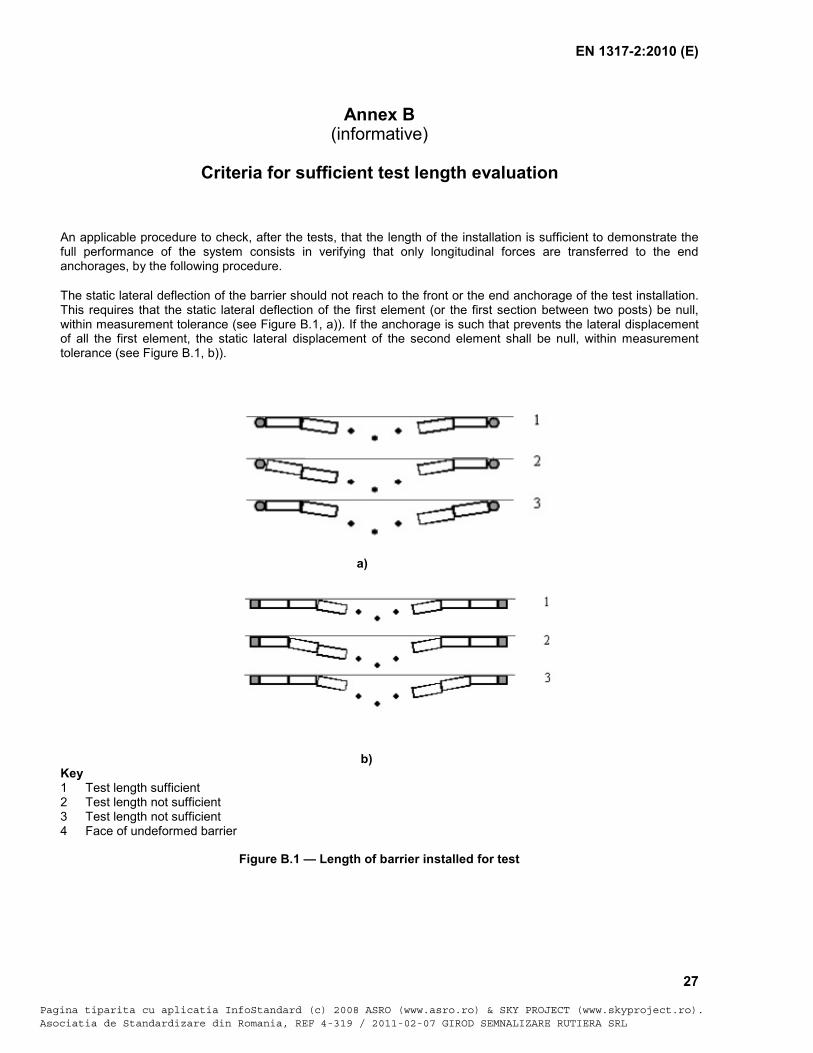
An applicable procedure to check, after the tests, that the length of the installation is sufficient to demonstrate the full performance of the system consists in verifying that only longitudinal forces are transferred to the end anchorages, by the following procedure.
The static lateral deflection of the barrier should not reach to the front or the end anchorage of the test installation. This requires that the static lateral deflection of the first element (or the first section between two posts) be null, within measurement tolerance (see Figure B.1, a)). If the anchorage is such that prevents the lateral displacement of all the first element, the static lateral displacement of the second element shall be null, within measurement tolerance (see Figure B.1, b)).
a)
b) Key 1 Test length sufficient 2 Test length not sufficient 3 Test length not sufficient 4 Face of undeformed barrier
Figure B.1 — Length of barrier installed for test
Pagina tiparita cu aplicatia InfoStandard (c) 2008 ASRO (www.asro.ro) & SKY PROJECT (www.skyproject.ro).Asociatia de Standardizare din Romania, REF 4-319 / 2011-02-07 GIROD SEMNALIZARE RUTIERA SRL
EN 1317-2:2010 (E)
28
Bibliography
[1] EN 1317-5:2007+A1:2008, Road restraint systems Part 5: Product requirements and evaluation of conformity for vehicle restraint systems
[2] ISO 6487, Road vehicles Measurement techniques in impact tests Instrumentation
Pagina tiparita cu aplicatia InfoStandard (c) 2008 ASRO (www.asro.ro) & SKY PROJECT (www.skyproject.ro).Asociatia de Standardizare din Romania, REF 4-319 / 2011-02-07 GIROD SEMNALIZARE RUTIERA SRL