
metode fizico-chimice combinate de tratare a apelor reziduale ...

Proiect cofinanțat din Fondul Social European prin Programul Operațional Capital Uman 2014-2020
Axa prioritară 6 - Educație și competențe Obiectiv specific 6.13 - Creșterea numărului absolvenților de învățământ terțiar universitar și nonuniversitar care își găsesc un loc de muncă urmare a accesului la activități de învățare la un potențial loc de muncă/cercetare/inovare, cu accent pe sectoarele economice cu potențial competitiv, identificate conform SNC, şi domeniile de specializare inteligentă, conform SNCDI Titlul proiectului: Excelența academică și valori antreprenoriale - sistem de burse pentru asigurarea oportunităților de formare și dezvoltare acompetențelor antreprenoriale ale doctoranzilor și postdoctoranzilor – ANTREPRENORDOC Contract nr. 36355/23.05.2019 POCU/380/6/13 - Cod SMIS: 123847
Beneficiar: Parteneri:
Universitatea Maritimă din Constanţa
Facultatea de Electromecanică Navală
Departamentul de Inginerie Mecanică ȋn Domeniu Mecanic şi Mediu
STUDII ŞI CERCETĂRI PRIVIND
SISTEMELE DE RECUPERARE A ENERGIEI
REZIDUALE LA NAVELE MARITIME
STUDIES AND RESEARCH ON WASTE
ENERGY RECOVERY SYSTEMS FOR SHIPS
REZUMAT ȋn limba engleză
Autor: Ing. Cătălin Faităr
Conducător științific: Prof.univ.dr.ing. Nicolae Buzbuchi
Lucrare realizată în cadrul proiectului
„Excelența academică și valori antreprenoriale - sistem de burse pentru
asigurarea oportunităților de formare și dezvoltare a competențelor
antreprenoriale ale doctoranzilor și postdoctoranzilor” –
ANTREPRENORDOC
Contract nr. 36355/23.05.2019 POCU/380/6/13 – Cod SMIS: 123847
Constanţa 2021
Studies and research on waste energy recovery systems for ships
1
Content
Chapter 1. Introduction .................................................................................................. 2
Chapter 2. Current state of energy efficiency optimization in shipping .................... 2
Chapter 3. Notions regarding the analysis of the energy systems of the ship.
Elements of calculation ................................................................................................... 3
Chapter 4. Study of the functional parameters of the power supply system as an
integral part of the waste heat recovery system ............................................................ 5
Chapter 5. Study of the functional parameters of freshwater generation system as
an integral part of the waste heat recovery system ..................................................... 7
Chapter 6. Study of the installation using exhaust gases from the main engine as an
integral part of the waste heat recovery system ........................................................... 8
Chapter 7. Experimental results validation ................................................................ 11
Chapter 8. Final conclusions, personal contributions and recommendations for
future work ..................................................................................................................... 13
Bibliography ................................................................................................................... 16
Studies and research on waste energy recovery systems for ships
2
Chapter 1. Introduction
The paper entitled "Studies and research on waste energy recovery systems for ships" is
structured in seven main chapters and conclusions, as follows: in the first chapter, will present
the overview of the importance and objectives of the thesis, in the second chapter will present
issues on the current state of implementation of energy technologies in ships, the third chapter
will deal with the notions of energy efficiency for the oil tanker taken as a reference, and the
fourth chapter will deal with supercharging as a basic process of main engine operation; the fifth
chapter will deal with the production of technical water on board the ship as a final element
regarding the use of the energy flow of the cooling water of the main engine, and in chapter six it
refers to the mathematical model of the energy flow obtained in the economizer with the help of
exhaust gases and will with captures the study of its behavior with the help of the CFD module
(Computational fluid dynamics) within Ansys Fluent, as well as the experimental validation by
performing measurements on the actual installation on board the reference ship in chapter seven.
Chapter eight will present the final conclusions of the thesis, personal contributions,
development directions and dissemination of research results.
The thesis thus elaborated is important, because it studies a way to improve the
efficiency of the entire ship by optimizing the on-board installations and obtains an experimental
validation on the efficiency for an oil tanker of 300000 dwt.
The thesis is also opportune because, in the current context, when international standards
impose a series of restrictions in terms of energy efficiency that must be respected, the paper
opens new perspectives on how to streamline ships.
This paper will focus on the following major objectives:
1) The current state of international norms on ship efficiency;
2) The current state of efficiency methods regarding merchant ships;
3) Energy analysis of residual energy flow recovery systems for the 300,000 dwt oil
tanker;
4) Analysis of the impact of supercharging of the main engine on the efficiency of the
ship;
5) Analysis of the efficiency of the ship by studying the energy flow of cooling water;
6) Modeling and studying the energy transfer using the CFD (Computational Fluid
Dynamics) module within Ansys Fluent in the recovery boiler;
7) Validation of the results by comparison with the results obtained by a 1: 1 scale
experiment.
Chapter 2. Current state of energy efficiency optimization in shipping
A ship needs fuel for both travel and on-board operations. In the most general case, the
fuel is converted on board the ship into energy in the form required for its end use: mechanical
Studies and research on waste energy recovery systems for ships
3
power for propulsion, electrical power for auxiliary board systems and thermal power for thermal
needs.
A ship is built and operated for a specific purpose, which varies from ship to ship (for
example, for freight, passenger or military transport etc.). To achieve its intended purpose, a ship
must be able to perform several functions in addition to propulsion. These can range from
carrying out on-board activities in a safe environment to providing accommodation facilities for
on-board crew.
In general, the energy required on board the ship is divided into three categories:
propulsion power: the movement of the ship is influenced to a large extent by the
resistance resulting from friction with water and to a small extent with air; this resistance
is directly influenced primarily by the speed of the ship, but also by the characteristics of
the ship's hull (shape of the ship's hull, its condition, wet surface etc.); external factors,
such as the deposition of various species of organisms on the living work of the ship, as
well as unfavorable weather conditions, directly influence the need for greater propulsion
power;
auxiliary electrical power: many on-board units require electricity to operate. Some of
them are found on all types of ships as basic elements in the correct operation, such as
navigation equipment, cooling and lubrication pumps, compressors in air conditioning
systems, ballast pumps, lights etc; we also have specific equipment depending on the type
of each ship, such as the inert gas installation for oil tanks, refrigerated containers for
container vessels, cargo loading pumps (also for oil tanks);
auxiliary thermal power: heat is generally required in three important directions: crew
comfort, fuel heating, and technical water generation; in a similar way to auxiliary
electric power, various types of ships require a certain amount of heat, as in the case of
oil tanks (for heating low-viscosity cargo) or the case of passenger ships, for the comfort
of those on board.
Chapter 3. Notions regarding the analysis of the energy systems of the ship.
Elements of calculation
To correctly understand the requirements of a system, we must first study its schematics.
In the case of energy systems, they require a detailed diagram of energy performance. In addition
to the standard data analyzed, energy and exergetic analysis is required. When dealing with
energy flows of any kind, the singular analysis of energy can lead to inconclusive results, not
taking into account the quality of energy. This problem can be partially solved by exergy
analysis. In the ship, exergy is defined as the maximum load of an aggregate coming from the
mechanical system in a specific reference environment.
The exergy content of a system depends on the quality of the energy contained.
Moreover, unlike energy, exergy is not conserved and can be destroyed, representing the
deterioration of energy quality.
The exergic content of a material flow is generally divided into four parts: physical,
chemical, kinetic and potential. Potential and kinetic exergy flows coincide with their energy
counterparts. In the case of chemical exergy, substantial differences can be found when
Studies and research on waste energy recovery systems for ships
4
analyzing systems involving more advanced chemistry; in this case, combustion is the only
chemical reaction considered.
Heat losses can be classified into high - temperature losses, medium - temperature and
low - temperature losses. On board ships with low-speed propulsion engines, heat recovery
systems operate in the range of 100–400 °C. Many residual energy recovery systems from
internal combustion engines are under development: for example the MAN WHR development
program for Tier III ternologies.
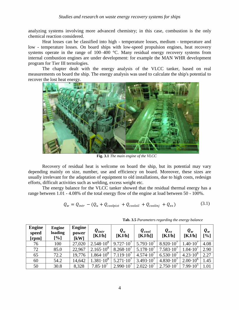
The chapter dealt with the energy analysis of the VLCC tanker, based on real
measurements on board the ship. The energy analysis was used to calculate the ship's potential to
recover the lost heat energy.
Fig. 3.1 The main engine of the VLCC
Recovery of residual heat is welcome on board the ship, but its potential may vary
depending mainly on size, number, use and efficiency on board. Moreover, these sizes are
usually irrelevant for the adaptation of equipment to old installations, due to high costs, redesign
efforts, difficult activities such as welding, excess weight etc.
The energy balance for the VLCC tanker showed that the residual thermal energy has a
range between 1.01 - 4.08% of the total energy flow of the engine at load between 50 - 100%.
𝑄𝑤 = 𝑄𝑖𝑛𝑡𝑟 − (𝑄𝑢 + 𝑄𝑐𝑜𝑜𝑙𝑝𝑖𝑠𝑡 + 𝑄𝑐𝑜𝑜𝑙𝑜𝑖𝑙 + 𝑄𝑐𝑜𝑜𝑙𝑖𝑛𝑗 + 𝑄𝑒𝑥 )
Tab. 3.5 Parameters regarding the energy balance
Engine
speed
[rpm]
Engine
loading
[%]
Engine
power
[kW]
𝑸𝒊𝒏𝒕𝒓
[KJ/h]
𝑸𝒖
[KJ/h]
𝑸𝒄𝒐𝒐𝒍
[KJ/h]]
𝑸𝒆𝒙
[KJ/h]
𝑸𝒘
[KJ/h]
𝑸𝒘
[%]
76 100 27,020 2.548·108 9.727·10
7 5.793·10
7 8.920·10
7 1.40·10
7 4.08
72 85.0 22,967 2.165·108 8.268·10
7 5.178·10
7 7.583·10
7 1.04·10
7 2.90
65 72.2 19,776 1.864·108 7.119·10
7 4.574·10
7 6.530·10
7 4.23·10
6 2.27
60 54.2 14,642 1.381·108 5.271·10
7 3.493·10
7 4.830·10
7 2.00·10
6 1.45
50 30.8 8,328 7.85·107 2.990·10
7 2.022·10
7 2.750·10
7 7.99·10
5 1.01
(3.1)
Studies and research on waste energy recovery systems for ships
5
The analyzes performed proved that the propulsion installation is the major consumer
(67.2%), but we were shown that neither the need for electricity (11.8%) and the heat fluxes
(21%) are not negligible. A large amount of energy is wasted into the environment by cooling
the engine and exhaust gases. Using energy analysis, the potential to implement a heat recovery
system on board can be estimated.
Chapter 4. Study of the functional parameters of the power supply system as an integral
part of the waste heat recovery system
In this chapter, was treated both theoretical calculation elements and real elements of the
operation of the turbocharging system, for the main reference engine.
I chose to treat this system because it is a main subassembly for the engine, in terms of
operation and thus its efficiency.
In the theoretical calculation I will start from the initial calculation data and I will expose
the geometric and functional parameters of the turbocharger.
The supercharger is defined by the joint operation of the turbine and the compressor. The
principle of operation consists in entraining the exhaust gases from the engine cylinders, in the
turbine blades. The turbine transmits the rotational movement of the compressor, and it drives
the working fluid (air) into the engine cylinders.
The components of flue gas turbochargers are subject to extreme operating conditions.
The exhaust gases up to a temperature of 650 °C pass continuously through the turbine
and heat its components, without its system of contraction cooling. In particular, the shaft
bearing must withstand high operating temperatures without ever breaking the lubrication
device.
On the compressor side, the air is heated to over 200 °C. High temperatures lead to
extreme thermal loads of the material in many locations. Speeds are extremely high: METxxSE
turbochargers run at speeds between 10,000 and 35,000 rpm, depending on size. In this respect,
the tangential speeds of 560 m / s and even more are reached at the compressor turbine, which
rises to 1.7 times the speed of sound or 2,000 km / h.
Centrifugal forces are extremely high: forces of several hundred kN can be easily applied
to the base of the turbine blade.
The complete engine gas exchange is performed by the flue gas turbocharger. For this
machine, the combustion air flow can reach 24 m3 / s. Simplified, it can be said that approx. 1/3
of the power produced by the engine is transferred to the turbocharger.
Starting from the fact that, out of the total amount of energy contained in the burned fuel
in a diesel engine, only 20% is used for the effective propulsion of the ship, shipbuilders act in
all ways to reduce energy losses and increase propulsion efficiency. Their attention is focused on
both the engine and the engine itself and the ship.
Studies and research on waste energy recovery systems for ships
6
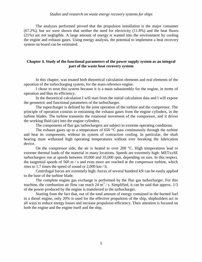
Fig. 4.1 Energy model
The turbocharger can be modeled by isentropic thermal efficiency. Compressor outlet
temperature is
𝑇𝑜𝑢𝑡 ,𝑐𝑜𝑚𝑝 = 𝑇𝑎𝑚𝑏 1
𝜂𝑐𝑜𝑚𝑝
𝑝𝑜𝑢𝑡 ,𝑐𝑜𝑚𝑝
𝑝𝑎𝑚𝑏
𝛾𝑎−1
𝛾𝑎 − 1
The power of the compressor can be modeled by
𝑃𝑐𝑜𝑚𝑝 = 𝑚 𝑐𝑜𝑚𝑝 𝑐𝑝𝑎𝑇𝑎𝑚𝑏1
𝜂𝑐𝑜𝑚𝑝
𝑝𝑜𝑢 𝑡 ,𝑐𝑜𝑚𝑝
𝑝𝑎𝑚𝑏
𝛾𝑎−1
𝛾𝑎 − 1
The power of the turbine can be modeled by
𝑃𝑡𝑢𝑟𝑏 = 𝑚 𝑡𝑢𝑟𝑏 𝐶𝑝𝑒𝑇𝑖𝑛 ,𝑡𝑢𝑟𝑏 𝜂𝑡𝑢𝑟𝑏 1 − 𝑝𝑜𝑢𝑡 ,𝑐𝑜𝑚𝑝
𝑝 𝑖𝑛 ,𝑡𝑢𝑟𝑏
𝛾−1
𝛾
The component that aims to enrich the mixture that will be consumed by the engine, is
the centrifugal compressor driven by the gas turbine.
The turbocharging process ensures the recovery of a fraction of the energy contained in
the flue gases emitted from the engine, which represents approximately 30-40% of the energy
released in the combustion process.
Air flow for gas exchange:
𝑑𝑠𝑔 = 𝑑𝑎𝑠𝑔 ∙ 𝑃𝑒 𝐾𝑔𝑎𝑒𝑟
Obviously, the internal combustion engine is a machine characterized by the presence of
stationary flow of the working fluid, as a result of which the turbine of the turbocharger group
must be able to operate in such conditions.
The efficiency of the operation of the turbocharger system related to the main propulsion
engine depends on the internal processes that take place in its operation, and also on the
environmental conditions. In this way, the direction of processing on the installation is dictated
(4.3)
(4.1)
(4.4)
(4.2)
Studies and research on waste energy recovery systems for ships
7
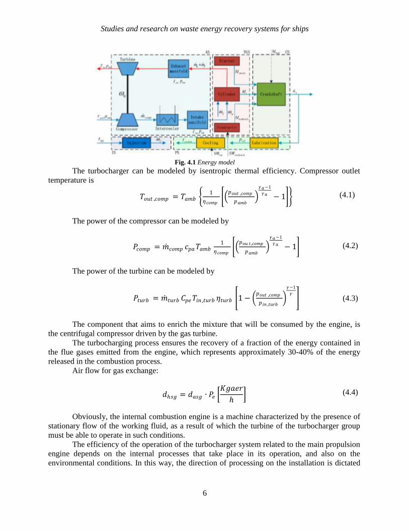
by the engine load, taking into account the extreme situations, corresponding to the operation of
the ship in special conditions (overload, tropical tem perature, arctic temperature etc).
Fig. 4.11 Turbocharger speed vs engine speed
Chapter 5. Study of the functional parameters of freshwater generation system as
an integral part of the waste heat recovery system
In this chapter I propose to deal with both theoretical and real elements of operation of
the freshwater generation system from the main engine of the ship.
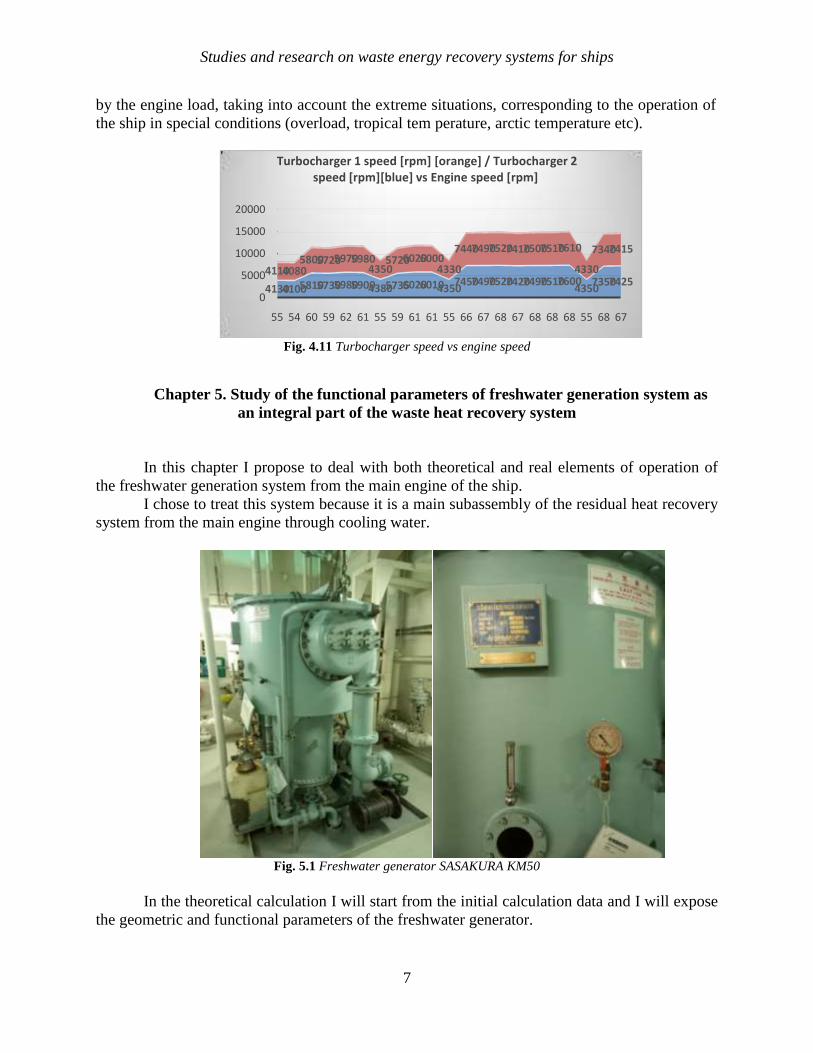
I chose to treat this system because it is a main subassembly of the residual heat recovery
system from the main engine through cooling water.
Fig. 5.1 Freshwater generator SASAKURA KM50
In the theoretical calculation I will start from the initial calculation data and I will expose
the geometric and functional parameters of the freshwater generator.
413041005810573059805900438057356020601043507450749075207420749075107600
435073507425
411040805800572059705980
4350572060206000
4330
7440749075207410750075107610
4330
73407415
0
5000
10000
15000
20000
55 54 60 59 62 61 55 59 61 61 55 66 67 68 67 68 68 68 55 68 67
Turbocharger 1 speed [rpm] [orange] / Turbocharger 2 speed [rpm][blue] vs Engine speed [rpm]
Studies and research on waste energy recovery systems for ships
8
In the final part of the chapter I will refer to the real parameters of the freshwater
generation system where I will draw operation diagrams to highlight as concretely as possible the
operation of this system on board the ship.
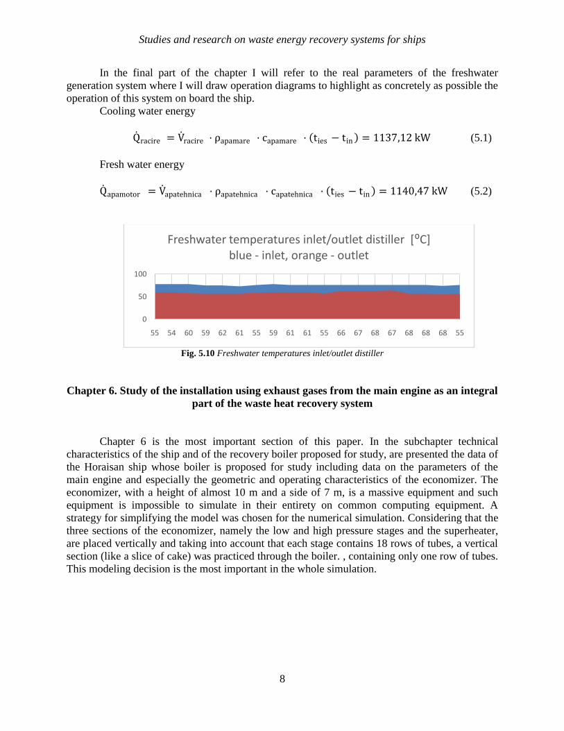
Cooling water energy
Q racire = V racire · ρapamare · capamare · ties − tin = 1137,12 kW (5.1)
Fresh water energy
Q apamotor = V apatehnica · ρapatehnica · capatehnica · ties − tin = 1140,47 kW (5.2)
Fig. 5.10 Freshwater temperatures inlet/outlet distiller
Chapter 6. Study of the installation using exhaust gases from the main engine as an integral
part of the waste heat recovery system
Chapter 6 is the most important section of this paper. In the subchapter technical
characteristics of the ship and of the recovery boiler proposed for study, are presented the data of
the Horaisan ship whose boiler is proposed for study including data on the parameters of the
main engine and especially the geometric and operating characteristics of the economizer. The
economizer, with a height of almost 10 m and a side of 7 m, is a massive equipment and such
equipment is impossible to simulate in their entirety on common computing equipment. A
strategy for simplifying the model was chosen for the numerical simulation. Considering that the
three sections of the economizer, namely the low and high pressure stages and the superheater,
are placed vertically and taking into account that each stage contains 18 rows of tubes, a vertical
section (like a slice of cake) was practiced through the boiler. , containing only one row of tubes.
This modeling decision is the most important in the whole simulation.
0
50
100
55 54 60 59 62 61 55 59 61 61 55 66 67 68 67 68 68 68 55
Freshwater temperatures inlet/outlet distiller [⁰C]blue - inlet, orange - outlet
Studies and research on waste energy recovery systems for ships
9
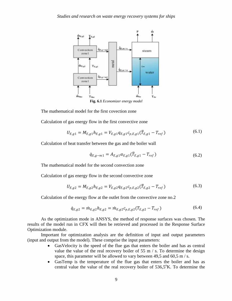
Fig. 6.1 Economizer energy model
The mathematical model for the first covection zone
Calculation of gas energy flow in the first convective zone
𝑈𝐸,𝑔1 = 𝑀𝐸 ,𝑔1𝐸,𝑔1 = 𝑉𝐸,𝑔1𝑞𝐸,𝑔1𝑐𝑝 ,𝐸,𝑔1(𝑇 𝐸,𝑔1 − 𝑇𝑟𝑒𝑓 )
Calculation of heat transfer between the gas and the boiler wall
𝑞 𝐸,𝑔−𝑚1 = 𝐴𝐸,𝑔1𝛼𝐸,𝑔1(𝑇 𝐸,𝑔1 − 𝑇𝑟𝑒𝑓 )
The mathematical model for the second convection zone
Calculation of gas energy flow in the second convective zone
𝑈𝐸,𝑔2 = 𝑀𝐸 ,𝑔2𝐸,𝑔2 = 𝑉𝐸,𝑔2𝑞𝐸,𝑔2𝑐𝑝 ,𝐸,𝑔2(𝑇 𝐸,𝑔2 − 𝑇𝑟𝑒𝑓 )
Calculation of the energy flow at the outlet from the convective zone no.2
𝑞 𝐸,𝑔2 = 𝑚 𝐸,𝑔2𝐸,𝑔2 = 𝑚 𝐸,𝑔2𝑐𝑝 ,𝐸,𝑔2(𝑇𝐸,𝑔2 − 𝑇𝑟𝑒𝑓 )
As the optimization mode in ANSYS, the method of response surfaces was chosen. The
results of the model run in CFX will then be retrieved and processed in the Response Surface
Optimization module.
Important for optimization analysis are the definition of input and output parameters
(input and output from the model). These comprise the input parameters:
GasVelocity is the speed of the flue gas that enters the boiler and has as central
value the value of the real recovery boiler of 55 m / s. To determine the design
space, this parameter will be allowed to vary between 49,5 and 60,5 m / s.
GasTemp is the temperature of the flue gas that enters the boiler and has as
central value the value of the real recovery boiler of 536,5oK. To determine the
(6.4)
(6.1)
(6.2)
(6.3)
Studies and research on waste energy recovery systems for ships
10
design space, this parameter will be allowed to vary between 482,54oK and
589,77oK.
LP1Velocity is the speed of the water that enters the low pressure stage LP and
has as central value the value of the real economizer of 0,28 m / s. To determine
the design space, this parameter will be allowed to vary between 0,252 and 0,308
m / s.
LP1Temp is the temperature of the water that enters the low pressure stage LP
and has as central value the value of the real economizer of 403,15oK. To
determine the design space, this parameter will be allowed to vary between
362,84oK and 443,47
oK.
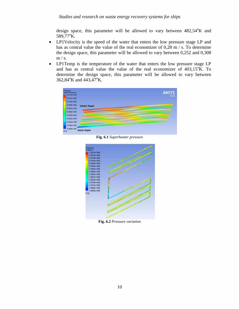
Fig. 6.1 Superheater pressure
Fig. 6.2 Pressure variation

Studies and research on waste energy recovery systems for ships
11
Chapter 7. Experimental results validation
Experimental validation for the turbocharger system
Fig. 7.1 Turbocharging system measuring points
Tab. 7.1 Calculated errors for turbocharging system
Theoretical air flow at
maximum main engine capacity
[m3/s]
Real air flow at maximum main
engine capacity
[m3/s]
Error
[%]
28 29,6 5,4
Turbocharger speed 1[rpm] Turbocharger speed 2[rpm]
6178 6173 0,08
Turbocharger lubricating oil
temperature difference 1 [oC]
Turbocharger lubricating oil
temperature difference 2 [oC]
11,8 11,19 5,16
Air cooler temperature
difference 1 [oC]
Air cooler temperature
difference 2 [oC]
69,52 69,19 0,47
Water cooler temperature
difference 1 [oC]
Water cooler temperature
difference 2 [oC]
12,52 9,85 21,3
Cooling air pressure drop no. 1
[mmH2O]
Cooling air pressure drop no. 2
[mmH2O]
89,9 105,9 15,1

Studies and research on waste energy recovery systems for ships
12
Experimental validation for the freshwater generation system
Fig. 7.2 Freshwater generation system measuring points
Tab. 7.2 Calculated errors for freshwater system
Fluxul
energetic
teoretic al
apei de mare
de răcire
(medie)
[kW]
Fluxul
energetic real
al apei sărate
de intrare de
răcire
[kW]
Eroare
[%]
Fluxul
energetic
teoretic al
apei tehnice
provenite de
la motorul
principal
[kW]
Fluxul
energetic real
al apei
tehnice
[kW]
Eroare
[%]
1191,4 1137,1 4,6 1124,2 1140,5 1,44
Experimental validation for the economizer
Fig. 7.3 Economizer measuring points
Studies and research on waste energy recovery systems for ships
13
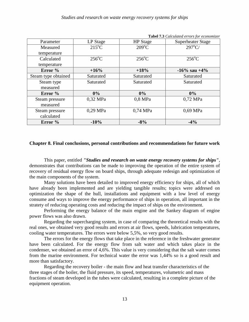
Tabel 7.3 Calculated errors for economizer
Parameter LP Stage HP Stage Superheater Stage
Measured
temperature
215oC 209
oC 297
oC/
Calculated
temperature
256oC 256
oC 256
oC
Error % +16% +18% -16% sau +4%
Steam type obtained Saturated Saturated Saturated
Steam type
measured
Saturated Saturated Saturated
Error % 0% 0% 0%
Steam pressure
measured
0,32 MPa 0,8 MPa 0,72 MPa
Steam pressure
calculated
0,29 MPa 0,74 MPa 0,69 MPa
Error % -10% -8% -4%
Chapter 8. Final conclusions, personal contributions and recommendations for future work
This paper, entitled "Studies and research on waste energy recovery systems for ships",
demonstrates that contributions can be made to improving the operation of the entire system of
recovery of residual energy flow on board ships, through adequate redesign and optimization of
the main components of the system.
Many solutions have been detailed to improved energy efficiency for ships, all of which
have already been implemented and are yielding tangible results; topics were addresed on
optimization the shape of the hull, installations and equipment with a low level of energy
consume and ways to improve the energy performance of ships in operation, all important in the
stratety of reducing operating costs and reducing the impact of ships on the environment.
Performing the energy balance of the main engine and the Sankey diagram of engine
power flows was also drawn.
Regarding the supercharging system, in case of comparing the theoretical results with the
real ones, we obtained very good results and errors at air flows, speeds, lubrication temperatures,
cooling water temperatures. The errors were below 5,5%, so very good results.
The errors for the energy flows that take place in the reference in the freshwater generator
have been calculated. For the energy flow from salt water and which takes place in the
condenser, we obtained an error of 4,6%. This value is very considering that the salt water comes
from the marine environment. For technical water the error was 1,44% so is a good result and
more than satisfactory.
Regarding the recovery boiler - the main flow and heat transfer characteristics of the
three stages of the boiler, the fluid pressure, its speed, temperatures, volumetric and mass
fractions of steam developed in the tubes were calculated, resulting in a complete picture of the
equipment operation.

Studies and research on waste energy recovery systems for ships
14
the optimization analysis of the numerical model comprises two phases, namely: determining the
optimal candidate, after which, with optimal thermo-hydraulic parameters, the complete thermo-
hydrodynamic model was generated to obtain the results necessary to compare the two models,
the real and the optimal. It has been seen that the optimized model delivers quantities of steam
with a higher quality than the real model. The most important conclusion is that the water
temperature at the entrance to the steps of the recovery boiler has the greatest impact on the
quality of the steam delivered.
In the case of temperatures recorded and calculated for the low and high pressure stages,
the calculated values are higher by 16% and 18%, respectively, indicating worsened heat transfer
conditions in these stages. In any case, the calculated and recorded values are comparable.
The types of steam calculated and those obtained in reality are identical, which shows
that the numerical model is valid.
The paper was based both on the theoretical study, on the simulation of energy flow
processes with the help of specialized electronic programs, but also on the study of real flows
with the help of a 1:1 scale study object, respectively the 300,000 dwt oil tank.
The possibility to perform, over a period of time at choice, exercises on a real ship at a
scale of 1:1, allowed the validation of the results obtained with the numerical program. The
validation was performed with the help of a chain of real installations: main engine -
turbocharging system - distiller - recovery boiler.
The results were satisfactory, which confirms that the program created can also be used
by students, PhD students, researchers and specialists who specialize in the divisions of special
ships, in deepening the understanding of waste energy recovery systems on board the ship.
Personal contributions
At this point we can specify thinks like the summary of the current state of play of
international standards on ship efficiency, the energy balance of the main engine on board the
ship both by classical calculations and on the basis of Sankey-type diagrams, sizing of the
turbocharger unit, drawing operating charts for reference engine turbochargers, based on
measurements made on board the ship; energy modeling of the turbocharger; energy modeling of
the distiller; the mathematical model of the recovery boiler - the mathematical model of the first
convection zone, of the second convection zone and the mathematical models of the metallic
zone respectively of steam and water;the following were performed: the simulation strategy with
finite volumes of the biphasic flow and boiling through the tubes of the recovery boiler, the
geometric model, the boundary conditions etc; the results obtained after the launch of the model
(pressures calculated per model, speeds calculated per model, volume fraction of vapors, etc.) -
finite element analysis of the fluid-structure interaction for the low pressure stage LP,
optimization analyzes of the numerical model.
Recommendation for future work
This paper opens a certain variety of possibilities related to possible studies and research
that can be done in the future, starting from this paper.
They are given below without any claim to completeness, as follows:
Studies and research on waste energy recovery systems for ships
15
• one of the first directions, and the most handy, is the improvement and improvement of
the calculation program through the variety of simulation conditions that may be required; thus
simulations can be made for different working conditions of the ship (ship in motion, ship at
anchor, ship in tropical or arctic conditions) when the working conditions of the main engine
differ;
• the geometry used is simplified but can be easily extended to a bunch of tubes for a
more realistic representation of the phenomena of flow and heat exchange in the economizer;
• you can try different pipe path geometries than the existing ones to increase the heat
exchange;
• solutions can be tried at the level of the ribbed tubes to increase the heat exchange.
It should be noted that the above proposals require enormous computational resources
and as such will require a significant investment in these resources to perform the simulations. I
am currently considering a collaboration with specialized research centers or at those companies
that have invested enough in new and modern CFD computing methodologies and software to
achieve what I set out to do in the future.
Studies and research on waste energy recovery systems for ships
16
Bibliography
[1] http://epochtimes-romania.com/news/comertul-maritim-este-esential-in-mediul-global---
145851. .
[2] Baldi, F. Thesis for the degree of doctor of engineering: Modelling, analysis and
optimisation of ship energy system, Chalmers University Of Technology, Gothenburg,
Sweden, 2016.
[3] Baldi, F., Hannes, J., Gabrielii, C., Andersson, K. Energy and Exergy Analysis of Ship
Energy Systems – The Case study of a Chemical Tanker, Gothenburg, Department of
Shipping and Marine Technology, Chalmers University of Technology Gothenburg,
Sweden, 2015.
[4] https://www.psih.uaic.ro/wp-content/uploads/dppd/postuniv/12-
13/IAC_curs_General.pdf.
[5] Baldi, F., Ahlgren, F., Nguyen, T., Thern, M. Energy and exergy analysis of a cruise ship,
Gothenburg, Department of Shipping and Marine Technology, Chalmers University of
Technology, Sweden, 2015.
[6] D. Shipping, Final report waste-heat-recovery-system MAN Waste Heat Recovery from
Combustion engine based onthe rankine cycle, 2020.
[7] http://dex.anidescoala.ro/cuvant/deadweight.
[8] Woud, H.K., Stapersma, D. Design of Propulsion and Electric Power Generation
Systems, London: Imarest Publications, United Kingdom, 2003.
[9] https://scialert.net/fulltext/?doi=ajms.2015.19.34.
[10] Carlton, J. Marine Propellers and Propulsion, Oxford: Butterworth-Heinemann, United
Kingdom, 2012.
[11] Faităr, C., Novac, I. A new approach on the upgrade of energetic system based on green
energy. A complex comparative analysis of the EEDI and EEOI, Iasi, ModTech
International Conference Modern Technologies in Industrial Engineering, 15-18 Jun,
2016.
[12] Baldi, F. Thesis For The Degree Of Doctor Of Engineering: Modelling, analysis and
optimisation of ship energy system, Gothenburg, Sweden, Department of Shipping and
Marine Technology, 2016.
[13] https://profs.info.uaic.ro/~fliacob/An2/2017-
2018/Modelare%20matematica_Resurse/Nicoleta%20Breaz%20a%20a_Modelare_matem
atica_prin_Matlab.pdf.
[14] L. M. P. N. a. A. N. IRENA - International Renewable Energy Agency, Renewable
Energy Options For Shipping Technology Brief, 2015.
[15] Faităr, C., Novac, I. Green energy propulsion, 2015.
[16] https://www.mhi-global.com.
[17] https://www.cnet.com.
[18] Faităr,C., Novac, I. Basic aspects and contributions to the optimization of energy systems
exploitation of a super tanker ship, 2017.
[19] www.pveducation.org/pvcdrom/modules/module-circuit-design2015,accessed07/04/2016.
Studies and research on waste energy recovery systems for ships
17
[20] Faităr, C., Novac, I. Basic aspects and contributions to the optimization of energy
systems exploitation of a super tanker ship, 2017.
[21] https://mechanicalxx.blogspot.ro/2016/09/steam-turbine_77.html..
[22] http s://www.kline.co.jp /en/csr/environment/efforts/sup p ression.html..
[23] Faităr, C., Nedelcu, A.T., Dumitrache, M. L. Improving the heat balance by using the
exhaust gases for a tanker ship, 2018.
[24] http s://worldmaritimenews.com.
[25] https://en.wikipedia.org.
[26] http://www.environmentalshipindex.org.
[27] http://www.environmentalshipindex.org/Public/Home.
[28] Faităr, C., Novac, I. A new approach on the upgrade of energetic system based on green
energy. A complex comparative analysis of the EEDI and EEOI, 2016.
[29] Faităr, C., Novac, I. Comparative Analysis of Energy Efficiency Indicators for a Crude
Oil Super-Tanker Ship, 2015.
[30] Faităr, C., Nedelcu, A.T., Buzbuchi, N. Stan, L.C. Consideration of Energy Efficiency
Operational Index evaluation, 2019.
[31] Faităr, C., Memet, F. Considerations upon the performances of the main naval engine
and energy efficiency evaluation, ModTech, Iaşi, 2019.
[32] Patterson,M 24, 377-390. 23, 1996.
[33] Kotas, T.J. The Exergy Method of Thermal Plant Analysis, Krieger Publishing, 1995.
[34] Szargut, J., Morris, D.R., Stewart, F.R Exergy Analysis of Thermal, Chemical, and
Metallurgical Processes, Hemisphere, 1988.
[35] Lior, N., Zhang, N. Energy, exergy, and Second Law performance criteria, Energy, 32,
281-296., 2007.
[36] Kotas, T Exergy criteria of performance for thermal plant: second of two papers on
exergy techniques in thermodynamic, International Journal of Heat and Fluid Flow, 2,
147-163. 25, 1980.
[37] Bruges, E. A. Performance of heat exchangers, Eng., vol. 204, pp. 225, 1957.
[38] Kotas, T. Exergy criteria of performance for thermal plant: second of two papers on
exergy techniques in thermodynamic plant analysis, Int. J. Heat Fluid Flow, vol. 2, pp.
147–163, 1980, 1980.
[39] Wik, C., Niemmi, S. Low emission engine technologies for future Tier 3 legislations,
Options and case studies, J Shipp Trade 2016:1–34, 2016.
[40] Mattarolo, L. Energy economy and heat recovery with particular reference to sea
transport, Int. J. Refrig., vol. 9, no. 1, pp. 6–12, 1986.
[41] Faităr, C. Considerații teoretice și practice de optimizare a exploatării sistemelor
energetice la un VLCC de 305,000 tdw, Bachelor’s Degree Paper, Constanța, 2015; p.113-
121, 2015.
[42] Faităr, C. Concepte de modernizare energetică a unui VLCC de 305,000 t.d.w. Calculul
şi proiectarea sistemelor energetice auxiliare, Master’s Degree Thesis, Constanța, p.89-
113, 2017.
Studies and research on waste energy recovery systems for ships
18
[43] Olszewski, W., Dzida, M. Selected combined power systems consisted of self- ignition
engine and steam turbine, Polish maritime research special issue 2018 s1 (97) vol. 25; pp.
198-20310.2478/pomr-2018-0042,2018.
[44] Wang, S., Liu, C., Zhou, Y. Study on Waste Heat Utilization Device of High-Temperature
Freshwater in the Modern Marine Diesel Engine, IOP Conf. Series: Earth and
Environmental Science 111(2018) 012009 doi:10.1088/1755-1315/111//012009, 2018.
[45] Altosole, M., Benvenuto, G., Campora, U., Laviola, M., Trucco, A. Waste Heat Recovery
from Marine Gas Turbines and Diesel Engines, Energies, 10, 718, 2017.
[46] Faităr, C., Novac, I. A new approach on the upgrade of energetic system basedon green
energy. A complex comparative analysis of the EEDI and EEOI, ModTech International
Conference Modern Technologies in Industrial Engineering 15-18 June 2016, Ramada H,
2016.
[47] ISGOTT, ISGOTT - International Safety Guide for Oil Tankers and Terminals, 2006.
[48] Faităr, C., Novac, I. Basic aspects and contributions to the optimization of energy
systems exploitation of a super tanker ship, ModTech International Conference Modern
Technologies in Industrial Engineering 14-17 June 2017, Sibiu, Romania.
[49] D. N. Veritas, Inspection and Maintenance of Oil tankers, 2012.
[50] Faităr, C., Nedelcu, A.T., Buzbuchi, N. Consideration of heat recovery for a diesel two-
stroke engine, 2018.
[51] Hyundai, Steam turbines, 2010.
[52] G. Lloyd, Rules for classification and construction VI additional rules and guidelines,
2013.
[53] Hyundai, Engine and machinery, 2012.
[54] Vafai, K., Ahmed, T. Heat transfer augmentation through convergence angles in a pipe,
Numerical Heat Transfer, Part A: Applications, 72:3, 197-21, 2017.
[55] Faităr, C., Nedelcu, A.T., Buzbuchi, N., Stan, L., Dumitrache, L.M. Considerations of
the energy balance of an internal combustion engine and the recovery of heat lost through
the cooling water, 2019.
[56] Horaisan VLCC Tanker Ship Technical Book, 2012.
[57] https://www.mhi-mme.com/products/boilerturbine/whrs.html;.
[58] http://marineengineeringonline.com/exhaust-gas-boiler.
[59] Lion, S., Vlaskos, I., Rouand, C., Taccani, R. Overview of the Activities on Heavy Duty
Diese1 Waste Heat Recovery with Organic Rankine Cycles (ORC), ECCO-MATE lELUT
FP7 Project, IV International Seminar on ORC Power Systems, ORC2017 13, 2017.
[60] Buzbuchi, N., Manea, L., Dragalina, A., Moroianu, C., Dinescu, C. Motoare navale.
Procese si caracteristici, Bucuresti: Editura Didactica si Pedagogica, 1997.
[61] Baldi, F., Hanssen, J., Gabrielii, G., Anderson, K. Energy and Exergy Analysis of Ship
Energy Systems, The Case study of a Chemical Tanker, Department of Shipping and
Marine Technology, Chalmers University of Technology Gothenburg, Sweden, Received
25, 2014.
[62] https://www.ilegis.ro/oficiale/index/act/219402.
[63] https://eur-lex.europa.eu/legal-content/RO/TXT/?uri=CELEX%3A32008R0440.
Studies and research on waste energy recovery systems for ships
19
[64] L. MITSUBISHI HE.AVV INDUSTRIES., MB06-Main Engine Final Drawing - Horaisan
Ship, 2012.
[65] KEIICHI, S. Development of High-efficiency Turbocharger MET-MA Series for Large-
Bore Diesel Engine, Nagasaki Shipyard & Machinery Works: Technical Review Vol. 43
No. 1, 2006.
[66] Cong, G., Gerasimos, T., Peilin, Z., Hui, G. Computational investigation of a large
containership propulsion, Appl. Energy 2014, 130, 370–383., 2014.
[67] https://moam.info/organizational-morphing-
technology_5b8dc802097c472a0f8b46aa.html.
[68] Wahlstrom, J., Eriksson, L. Modelling diesel engines with a variable-geometry
turbocharger and exhaust gas, Proc. Inst.Mech. Eng. Part D J. Automob. Eng.225, 960–
986., 2011.
[69] Yin, J., Su, T., Guan, Z., Chu, Q., Meng, C., Jia, L Modeling and Validation of a Diesel
Engine with, Energies, 10, 685; doi:10.3390/en10050685, 2017.
[70] https://inmateh.eu/INMATEH_1_2013/8_Marinuc%20M.pdf.
[71] Buzbuchi N., Manea, L., Dragalina, A., Moroianu, C. Motoare navale. Procese şi
caracteristici, Editura Didactică şi Pedagogică, Bucureşti , 1997.
[72] Buzbuchi, N.,Şoloiu, V., Dinescu, C. Motoare Navale. Supraalimentare Dinamică,
Editura Didactică şi Pedagogică R.A. Bucureşti, 1998.
[73] I. 15748-1:2002, ISO 15748-1:2002 - Ships and marine Technology (Nave și tehnologii
marine) - Alimentarea cu apă potabilă a navei și structurilor navale; Planificare și
proiectare.
[74] I. 19458:2006, ISO 19458:2006 - Water quality (Calitatea apei) - Mostre pentru analiza
microbiologică.
[75] I. 17025:2005, ISOIIEC 17025:2005 - General requirements for the competence of testing
and calibration laboratories (Cerințe generale pentru calibrarea laboratoarelor și
testarea competenței).
[76] Cipollina, A., Micale, G., Rizzuti, L. Seawater desalination: conventional and renewable
energy process,. Springer Science & Business Media., 2009.
[77] M. H. I. Ltd, Mitsubishi Heavy Industry Ltd - MJ12-FW Generator (Including Instruction
Book), 2012, 2012.
[78] Alfa Laval, https://www.alfalaval.com/products/process-solutions/fresh-water-
generation/multi-effect-desalination/mep-multi-effect-plate-evaporator/.
[79] Kakac, S., Liu, S. Heat Exchangers Selection, Rating and Thermal Design, CRC:USA.,
2002.
[80] Alfa Laval - heat exchange, https://www.alfalaval.com/media/stories/beverage-
processing/plate-heat-exchangers-boost-efficiency-at-leading-whisky-distillery/.
[81] Abu-Khader, M. M. Better thermal calculations using modified generalized Leveque
equations for Chevron plate heat exchangers, International Journal of Green Energy, 4,
351-366, 2007.
[82] http://mfame.guru/heat-recovery-system-operation-and-experience.
[83] Muley, A., Manglik, R. M. Experimental study of turbulent flow heat transfer and
Studies and research on waste energy recovery systems for ships
20
pressure drop in a plate heat exchanger with chevron plates, ASME Journal of Heat
Transfer, 121 (1), 110-117., 1999.
[84] Cieslinski, J., Fiuk, A., Typinski, K. Heat transfer in plate heat exchanger channels:
Experimental validation of selected correlation equations.Archives of Thermodynamics,
37 (3), 19-29., 2016.
[85] Soto, J. A., Martinez, M. T.,Magana, J. L. Theoretical-experimental study of the effect of
the external plates on the thermal performance of a plate heat exchanger, Chemical
Engineering and Science, 3 (1), 12-18., 2015.
[86] Çengel, Y. Heat and mass transfer: A practical approach. (3rd edition), McGraw-
Hill,USA, 2011.
[87] Wright, A., Heggs, P. J. Rating calculation for plate heat exchanger effectiveness and
pressure drop using existing performance data, Transactions of the Institution of
Chemical Engineers, 80, 309-312., 2002.
[88] Khan, T. S., Chyu, M. C., Ayub, Z. B. Experimental investigation of single phase
convective heat transfer coefficient in a corrugated plate heat exchanger for multiple
plate configurations, Applied Thermal Engineering, 30, 1058-1065., 2010.
[89] Demirel, K. Gemimühendisleriiçinpompauygulamaları. İstanbul: BirsenYayınevi., 2007.
[90] https ://www.mhimme.com/products/engine/..
[91] Kralj, P., Martinović, D., Analysis of thermodynamic and technological basics of the
marine fresh water generator model, University of Rijeka , Received 9 May 2017;
Accepted 4 October 2017,.
[92] Lior, N. Measurements and Control in Water Desalination, Elsevier, Amsterdam, 1986.
[93] Kralj, P. Model generatora slatke vode, doktorska disertacija (A Fresh Water Generator
Model), Ph.D. Thesis, Pomorski fakultet Sveučilišta u Rijeci, Rijeka, 2012.
[94] Bahar, R., Hawlader, M.N.A. Desalination: Conversion of Seawater to Freshwater, 2nd
International Conference on Mechanical, Automotive and Aerospace Engineering, Kuala
Lumpur, 2013.
[95] Faităr, C. Considerații teoretice și practice de optimizare a exploatării sistemelor
energetice la un VLCC de 305000 tdw, License Degree, Constanța, 2017; p.113-121;,
2017.
[96] https://www.marinetraffic.com/.
[97] Faităr, C., Buzbuchi, N., Stan, L. Fluid structure interaction analysis of a naval
economizer, 2019.
[98] Horaisan, Horaisan ME07-Instruction Book For Exh. Gas Economizer.
[99] https://marine.mandieselturbo.com.
[100] http://www.machineryspaces.com/boiler.html.
[101] Sørensen, K., Condra, T. Modeling and simulating fire tube boiler performance, 2003.
[102] Amsallem, D., Farhat, C., Lieu, T. Aeroelastic analysis of F-16 and F-18/A
conFigurations using adapted CFD-based reduced-order models. In: 48th
AIAA/ASME/ASCE/AHS/ASC Structures, Structural Dynamics, and Materials Conference,
Honolulu, HI, USA, 2007.
[103] https://www.researchgate.net.
Studies and research on waste energy recovery systems for ships
21
[104] Horaisan, Horaisan ME02-Exh. Gas Economizer.
[105] http://www.marineinsight.com/naval.
[106] http://www.mes.it.
[107] https://worldmaritimenews.com/archives/60495/japan-mhi-develops-uec-lsgi-low-speed-
df-diesel-engine.
[108] Batina, J.T. Unsteady Euler airfoil solutions using unstructured dynamic meshes, AIAA J
28(8):1381–1388, 1990.
[109] Bazilevs, Y., Calo, V.M., Hughes,T., Zhang, Y. Isogeometric fluid-structure interaction:
theory, algorithms, and computations, Comput Mech 43(1):3–37, 2008.