Proiect: Laseri de Tip Ghid de Unda obtinuti prin Tehnica ...ecs.inflpr.ro/rapoarte_contracte/01d....
61
Proiect: Laseri de Tip Ghid de Unda obtinuti prin Tehnica Scrierii Directe cu Pulsuri Laser cu durata de ordinul Femtosecondelor (PN-II-ID-PCE-2011-3-0363); IDEI 36/06.10.2011 - 1/10 - RAPORT STIINTIFIC privind implementarea proiectului in perioada ianuarie - decembrie 2014 1. Emisie in laseri de tip ghid de unda realizati in medii Nd:YAG de tip policristalin (ceramice) prin tehnica scrierii cu pulsuri laser cu durata de ordinul femtosecundelor (fs) Au fost realizate ghiduri de unda in medii laser Nd:YAG de tip ceramic si a fost obtinuta emisie laser la 1.06 μm si 1.32 μm folosind pompajul cu dioda laser la 807 nm. In Fig. 1.1 este prezentat montajul experimental utilizat pentru scrierea structurilor tip ghid de unda in mediile laser Nd:YAG de tip ceramic. Sistemul laser (Clark CPA-2101) livreaza pulsuri la lungimea de unda 775 nm cu durata de 200 fs. Rata de repetitie a pulsurilor este 2.0 kHz si valoarea maxima a energiei pe puls ajunge pana la 0.6 mJ. Energia pulsurilor a fost controlata utilizand o lama jumatate de unda (λ/2), un polarizor (P) si filtre neutre calibrate (F). Pentru focalizarea fasciculului laser a fost utilizata o lentila acromata (L) cu distanta focala de 7.5 mm si apertura numerica NA= 0.3. Diametrul fasciculului, in aer, a fost masurat ca fiind ~5.0 µm. Fiecare mediu Nd:YAG a fost pozitionat pe un sistem de translatie Oxyz motorizat care a permis miscarea controlabila pe toate cele trei directii. Ghidurile au fost scrise pe directia Ox, iar viteza de deplasare a sistemului de translatie a fost 50 µm/s. Procesul a fost monitorizat folosind o camera video. Au fost folosite doua medii active de Nd:YAG (Baikoswski Co. Ltd., Japonia) cu nivel de dopaj de 0.7-at.% si 1.1-at.% Nd. Suprafetele laterale ale fiecarui mediu Nd:YAG au fost slefuite dupa procesul de inscriptionare lungimea fianala a mediilor find l~7.8 mm. Fig. 1.1 Montajul experimental folosit pentru scrierea ghidurilor de unda in mediile laser Nd:YAG de tip ceramic. P: polarizor; λ/2= lama ‘jumatate de unda’; F: filtru neutru. In Fig. 1.2 prezentam imagini ale ghidurilor scrise in cele doua medii de Nd:YAG ceramic. Pentru inceput a fost inscriptionat un ghid (Fig. 1.2(a)) format din doua linii (cu distanta dintre linii de w= 50 µm). Apoi, pentru a creste dimensiunea ghidului pe directia Oz, a fost realizata o structura formata din sase linii, ca in Fig. 1.2(b). Astfel, au fost scrise doua ghiduri, fiecare avand sase linii, primul cu distanta w= 50 µm (Fig. 1.2(b)) si al doilea cu distanta 2w= 50 µm (Fig. 1.2(c)); acestea au fost indicate prin WG-1 si WG-2, respectiv. Energia pulsurilor fs-laser a fost de 2.0 µJ. Apoi, au fost realizate doua ghiduri cilindrice, primul cu diametrul φ= 50 µm (Fig. 1.2(d), DWG-1) si al doilea cu φ= 100 µm (Fig. 1.2(d), DWG-2). Aceste ghiduri au fost realizate dupa urmatorul algoritm: Au fost inscriptionate mai multe linii cu distanta dintre ele de 5 sau 6 µm la diferite adancimi astfel incat acestea sa incadreze o regiune circulara cu indicele de refractie nemodificat. Pentru aceste structuri, energia pulsurilor laser a fost de 1.0 µJ. Toate ghidurile au fost centrate la adancimea h= 500 µm sub suprafata mediilor Nd:YAG. Fig. 1.2 Fotografii ale diferitelor ghiduri de unda realizate in Nd:YAG ceramic. a) Ghid de tip ‘doua linii’ cu distanta w = 50 μm, sau cu dimensiune crescuta pe Oz prin trasarea a 6 (sase) linii plasate la distanta b) w = 50 μm (WG-1) si c) 2w= 100 μm (WG-2). Ghiduri circulare cu diametrul d) φ= 50 μm (DWG-1) and e) 2φ= 100 μm (DWG-2).
Transcript of Proiect: Laseri de Tip Ghid de Unda obtinuti prin Tehnica ...ecs.inflpr.ro/rapoarte_contracte/01d....
Proiect: Laseri de Tip Ghid de Unda obtinuti prin Tehnica Scrierii Directe cu Pulsuri Laser cu durata de ordinul Femtosecondelor
(PN-II-ID-PCE-2011-3-0363); IDEI 36/06.10.2011
- 1/10 -
RAPORT STIINTIFIC
privind implementarea proiectului in perioada ianuarie - decembrie 2014
1. Emisie in laseri de tip ghid de unda realizati in medii Nd:YAG de tip policristalin (ceramice) prin tehnica
scrierii cu pulsuri laser cu durata de ordinul femtosecundelor (fs)
Au fost realizate ghiduri de unda in medii laser Nd:YAG de tip ceramic si a fost obtinuta emisie laser la 1.06
µm si 1.32 µm folosind pompajul cu dioda laser la 807 nm. In Fig. 1.1 este prezentat montajul experimental
utilizat pentru scrierea structurilor tip ghid de unda in mediile laser Nd:YAG de tip ceramic. Sistemul laser (Clark
CPA-2101) livreaza pulsuri la lungimea de unda 775 nm cu durata de 200 fs. Rata de repetitie a pulsurilor este 2.0
kHz si valoarea maxima a energiei pe puls ajunge pana la 0.6 mJ. Energia pulsurilor a fost controlata utilizand o
lama jumatate de unda (λ/2), un polarizor (P) si filtre neutre calibrate (F). Pentru focalizarea fasciculului laser a
fost utilizata o lentila acromata (L) cu distanta focala de 7.5 mm si apertura numerica NA= 0.3. Diametrul
fasciculului, in aer, a fost masurat ca fiind ~5.0 µm. Fiecare mediu Nd:YAG a fost pozitionat pe un sistem de
translatie Oxyz motorizat care a permis miscarea controlabila pe toate cele trei directii. Ghidurile au fost scrise pe
directia Ox, iar viteza de deplasare a sistemului de translatie a fost 50 µm/s. Procesul a fost monitorizat folosind o
camera video. Au fost folosite doua medii active de Nd:YAG (Baikoswski Co. Ltd., Japonia) cu nivel de dopaj de
0.7-at.% si 1.1-at.% Nd. Suprafetele laterale ale fiecarui mediu Nd:YAG au fost slefuite dupa procesul de
inscriptionare lungimea fianala a mediilor find l~7.8 mm.
Fig. 1.1 Montajul experimental folosit pentru scrierea ghidurilor de unda in mediile laser Nd:YAG de tip ceramic.
P: polarizor; λ/2= lama ‘jumatate de unda’; F: filtru neutru.
In Fig. 1.2 prezentam imagini ale ghidurilor scrise in cele doua medii de Nd:YAG ceramic. Pentru inceput a fost
inscriptionat un ghid (Fig. 1.2(a)) format din doua linii (cu distanta dintre linii de w= 50 µm). Apoi, pentru a creste
dimensiunea ghidului pe directia Oz, a fost realizata o structura formata din sase linii, ca in Fig. 1.2(b). Astfel, au
fost scrise doua ghiduri, fiecare avand sase linii, primul cu distanta w= 50 µm (Fig. 1.2(b)) si al doilea cu distanta
2w= 50 µm (Fig. 1.2(c)); acestea au fost indicate prin WG-1 si WG-2, respectiv. Energia pulsurilor fs-laser a fost de
2.0 µJ. Apoi, au fost realizate doua ghiduri cilindrice, primul cu diametrul φ= 50 µm (Fig. 1.2(d), DWG-1) si al doilea
cu φ= 100 µm (Fig. 1.2(d), DWG-2). Aceste ghiduri au fost realizate dupa urmatorul algoritm: Au fost inscriptionate
mai multe linii cu distanta dintre ele de 5 sau 6 µm la diferite adancimi astfel incat acestea sa incadreze o regiune
circulara cu indicele de refractie nemodificat. Pentru aceste structuri, energia pulsurilor laser a fost de 1.0 µJ.
Toate ghidurile au fost centrate la adancimea h= 500 µm sub suprafata mediilor Nd:YAG.
Fig. 1.2 Fotografii ale diferitelor ghiduri de unda realizate in Nd:YAG ceramic. a) Ghid de tip ‘doua linii’ cu distanta w = 50 μm, sau
cu dimensiune crescuta pe Oz prin trasarea a 6 (sase) linii plasate la distanta b) w = 50 μm (WG-1) si c) 2w= 100 μm (WG-2).
Ghiduri circulare cu diametrul d) φ= 50 μm (DWG-1) and e) 2φ= 100 μm (DWG-2).
Proiect: Laseri de Tip Ghid de Unda obtinuti prin Tehnica Scrierii Directe cu Pulsuri Laser cu durata de ordinul Femtosecondelor
(PN-II-ID-PCE-2011-3-0363); IDEI 36/06.10.2011
- 2/10 -
Fenomenul de ghidare are loc intre liniile paralele ale structurilor WG-1 si WG-2 sau in interiorul structurilor
cilindrice DWG-1 si DWG-2. Pierderile de propagareau fost determinate folosind radiatia polarizata a unui laser
He-Ne; fasciculul laser a fost focalizat in fiecare ghid, iar puterea fasciculului a fost masurata inainte si dupa
fiecare ghid. Indiferent de mediul Nd:YAG ceramic, pierderile la lungimea de unda 632.8 nm au fost ~0.5 dB/cm
pentru WG-1 si de la 0.6 pana la 0.7 dB/cm pentru WG-2. In cazul ghidurilor cilindrice pierderile au avut valori mai
ridicate, de la 1.0 la 1.2 dB/cm pentru DWG-1 si de la 1.5 pana la 1.8 dB/cm pentru DWG-2.
In cadrul experimentelor laser, fiecare mediu de Nd:YAG ceramic a fost amplasat intr-un rezonator plan-plan.
Oglinda de pompaj a fost depusa cu reflectivitate ridicata (R>0.998) la lungimea de unda a emisiei laser (λem),
adica 1.06 µm sau 1.32 µm si cu transmisie ridicata (T>0.98) la lungimea de unda de pompaj (λp=807 nm). Au fost
utilizate oglinzi de extractie cu transmisii diferite la λem, acestea fiind pozitionate cat mai aproape de mediul laser;
in plus, fiecare mediu a fost amplasat pe un suport din aluminiu, insa fara racire aditionala.
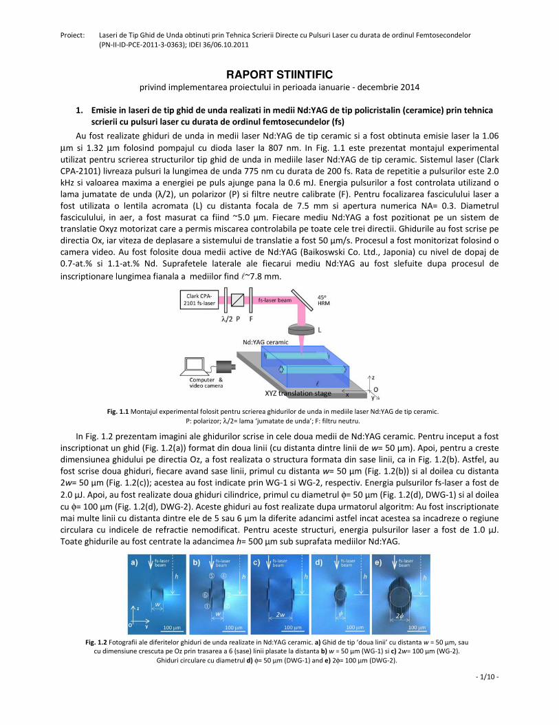
Fig. 1.3 a) Energia pulsurilor laser emise la 1.06 μm, obtinute in diferite ghiduri inscriptionate in mediul 0.7-at.%
Nd:YAG ceramic, rezonator cu oglinda OCM avand transmisia T = 0.05. Sunt prezentate distributiile in camp apropiat al
fasciculului laser obtinut de la b) mediul Nd:YAG, emisie in bulk si in ghidurile c) DWG-2 and d) WG-2.
Pompajul a fost facut la λp= 807 nm cu dioda laser (Limo Co., Germania). Radiatia emisa de dioda laser a fost
cuplata intr-o fibra cu diametrul φ=100 µm si NA= 0.22. Dioda a functionat atat in regim quasi-continuu (durata
pulsului de pompaj de 1 ms si rata de repetitie 10 Hz) cat si in regim de unda continua. Fasciculul de pompaj a fost
focalizat in mediul laser folosind o lentila de colimare cu distanta focala de 50 mm si o lentila de focalizare cu
distanta focala 30 mm. Pentru ghidurile WG-1 si WG-2 a fost introdus un polarizor intre lentile.
In Fig. 1.3 sunt prezentate caracteristicile emisiei laser la lungimea de unda 1.06 µm ale ghidurilor realizate in
mediul 0.7-at.% Nd:YAG ceramic, pentru pompaj in regim quasi-cw. Transmisia oglinzii de iesire la λem a fost
T=0.05. Pentru ghidul DWG-2 a fost masurata o valoare maxima a energiei Ep= 2.8 mJ, corespunzatoare unei
energii de pompaj Epump= 13.1 mJ. Eficienta optica (ηo) a fost determinata ca fiind 0.21. Panta eficientei (masurata
in functie de energia de pompaj) a fost ηs= 0.23. Trebuie mentionat ca mediul de Nd:YAG ceramic nemodificat a
generat pulsuri cu energia Ep= 5.95 mJ (η0~0.45) si panta eficientei ηs= 0.46. Eficienta de absorbtie a pompajului
(ηa) in mediul laser cu indicele de refractie nemodificat a fost masurata ca fiind 0.71, iar eficienta cu care a fost
focalizat fasciculul de pompaj in structura DWG-2 a fost evaluata ca fiind aproximativ unitara. In acest fel,
performantele mai scazute ale ghidului DWG-2 se datoreaza pierderilor de propagare mai ridicate fata de cele ale
mediului Nd:YAG nemodificat (aceastea au fost determinate ca fiind 0.2 dB/cm la 632.8 nm). Pentru ghidul liniar
WG-2 a fost masurata energia Ep= 0.8 mJ pentru un pompaj Epump= 4.8 mJ (ηo~0.17) si panta eficientei ηs= 0.22. In
Fig. 1.3 se poate observa de asemenea distributia fasciculului laser. Aceasta a inregistrata cu o camera CCD
Spiricon (model SP620U, zona spectrala 190-1100 nm). Factorul de calitate M2 al fasciculului laser (determinat
prin metoda 10%-90% knife edge) a fost masurat ca fiind 1.65 pentru emisia la 1.06 µm in mediul Nd:YAG
nemodificat (Fig. 1.3(b)); pentru ghidurile de unda calitatea fasciculului a scazut, fiind M2~10.1 in cazul ghidului
cilindric DWG-2 (Fig. 1.3(c)) si M2~3.9 pentru ghidul liniar WG-2 (Fig. 1.3(d)).
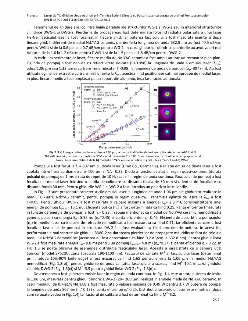
De asemenea a fost generata emisie laser in regim de unda continua. In Fig. 1.4 este aratata puterea de iesire
la 1.06 µm, masurata pentru ghidul cilindric DWG-2 (2φ= 100 µm) realizat in ambele medii de Nd:YAG ceramic. In
cazul mediului de 0.7-at.% Nd:YAG a fost masurata o valoare maxima de 0.49 W pentru 3.7 W putere de pompaj
la lungimea de unda 807 nm (ηo~0.13) si panta eficientei ηs~0.25. Distributia fasciculului laser este simetrica (dupa
cum se poate vedea in Fig. 1.4) iar factorul de calitate a fost determinat ca fiind M2~3.2.
Proiect: Laseri de Tip Ghid de Unda obtinuti prin Tehnica Scrierii Directe cu Pulsuri Laser cu durata de ordinul Femtosecondelor
(PN-II-ID-PCE-2011-3-0363); IDEI 36/06.10.2011
- 3/10 -
Fig. 1.4 Puterea fasciculului laser la 1.06 µm in regim de emisie cw, oglinda OCM cu T= 0.05. Este aratata
distributia fasciculului laser (in camp apropiat).
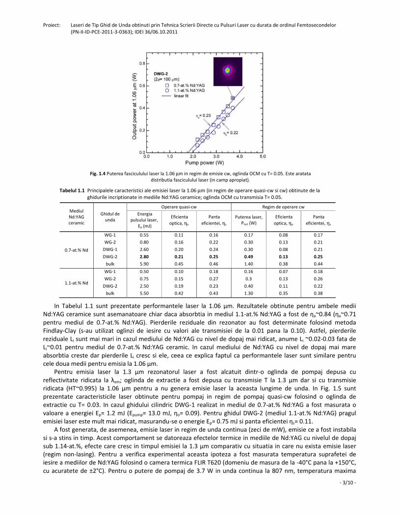
Tabelul 1.1 Principalele caracteristici ale emisiei laser la 1.06 µm (in regim de operare quasi-cw si cw) obtinute de la
ghidurile incriptionate in mediile Nd:YAG ceramice; oglinda OCM cu transmisia T= 0.05.
Operare quasi-cw Regim de operare cw Mediul
Nd:YAG
ceramic
Ghidul de
unda
Energia
pulsului laser,
Ep (mJ)
Eficienta
optica, ηo
Panta
eficientei, ηs
Puterea laser,
Pout (W)
Eficienta
optica, ηo
Panta
eficientei, ηs
0.7-at.% Nd
WG-1
WG-2
DWG-1
DWG-2
bulk
0.55
0.80
2.60
2.80
5.90
0.11
0.16
0.20
0.21
0.45
0.16
0.22
0.24
0.25
0.46
0.17
0.30
0.30
0.49
1.40
0.08
0.13
0.08
0.13
0.38
0.17
0.21
0.21
0.25
0.44
1.1-at.% Nd
WG-1
WG-2
DWG-2
bulk
0.50
0.75
2.50
5.50
0.10
0.15
0.19
0.42
0.18
0.27
0.23
0.43
0.16
0.3
0.40
1.30
0.07
0.13
0.11
0.35
0.18
0.26
0.22
0.38
In Tabelul 1.1 sunt prezentate performantele laser la 1.06 µm. Rezultatele obtinute pentru ambele medii
Nd:YAG ceramice sunt asemanatoare chiar daca absorbtia in mediul 1.1-at.% Nd:YAG a fost de ηa~0.84 (ηa~0.71
pentru mediul de 0.7-at.% Nd:YAG). Pierderile reziduale din rezonator au fost determinate folosind metoda
Findlay-Clay (s-au utilizat oglinzi de iesire cu valori ale transmisiei de la 0.01 pana la 0.10). Astfel, pierderile
reziduale Li sunt mai mari in cazul mediului de Nd:YAG cu nivel de dopaj mai ridicat, anume Li ~0.02-0.03 fata de
Li~0.01 pentru mediul de 0.7-at.% Nd:YAG ceramic. In cazul mediului de Nd:YAG cu nivel de dopaj mai mare
absorbtia creste dar pierderile Li cresc si ele, ceea ce explica faptul ca performantele laser sunt similare pentru
cele doua medii pentru emisia la 1.06 µm.
Pentru emisia laser la 1.3 µm rezonatorul laser a fost alcatuit dintr-o oglinda de pompaj depusa cu
reflectivitate ridicata la λem; oglinda de extractie a fost depusa cu transmisie T la 1.3 µm dar si cu transmisie
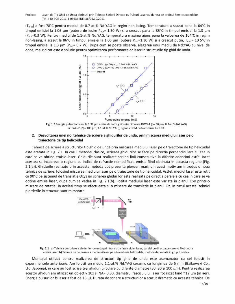
ridicata (HT~0.995) la 1.06 µm pentru a nu genera emisie laser la aceasta lungime de unda. In Fig. 1.5 sunt
prezentate caracteristicile laser obtinute pentru pompaj in regim de pompaj quasi-cw folosind o oglinda de
extractie cu T= 0.03. In cazul ghidului cilindric DWG-1 realizat in mediul de 0.7-at.% Nd:YAG a fost masurata o
valoare a energiei Ep= 1.2 mJ (Epump= 13.0 mJ, ηo= 0.09). Pentru ghidul DWG-2 (mediul 1.1-at.% Nd:YAG) pragul
emisiei laser este mult mai ridicat, masurandu-se o energie Ep= 0.75 mJ si panta eficientei ηs= 0.11.
A fost generata, de asemenea, emisie laser in regim de unda continua (zeci de mW), emisie ce a fost instabila
si s-a stins in timp. Acest comportament se datoreaza efectelor termice in mediile de Nd:YAG cu nivelul de dopaj
sub 1.14-at.%, efecte care cresc in timpul emisiei la 1.3 µm comparativ cu situatia in care nu exista emisie laser
(regim non-lasing). Pentru a verifica experimental aceasta ipoteza a fost masurata temperatura suprafetei de
iesire a mediilor de Nd:YAG folosind o camera termica FLIR T620 (domeniu de masura de la -40°C pana la +150°C,
cu acuratete de ±2°C). Pentru o putere de pompaj de 3.7 W in unda continua la 807 nm, temperatura maxima
Proiect: Laseri de Tip Ghid de Unda obtinuti prin Tehnica Scrierii Directe cu Pulsuri Laser cu durata de ordinul Femtosecondelor
(PN-II-ID-PCE-2011-3-0363); IDEI 36/06.10.2011
- 4/10 -
(Tmax) a fost 78°C pentru mediul de 0.7-at.% Nd:YAG in regim non-lasing. Temperatura a scazut pana la 64°C in
timpul emisiei la 1.06 µm (putere de iesire Pout= 1.30 W) si a crescut pana la 85°C in timpul emisiei la 1.3 µm
(Pout=0.3 W). Pentru mediul de 1.1-at.% Nd:YAG, temperatura maxima ajuns pana la valoarea de 104°C in regim
non-lasing, a scazut la 86°C in timpul emisiei la 1.06 µm (putere Pout=1.30 W) si a crescut putin, Tmax= 10 5°C in
timpul emisiei la 1.3 µm (Pout= 0.7 W). Dupa cum se poate observa, alegerea unui mediu de Nd:YAG cu nivel de
dopaj mai ridicat este o solutie pentru optimizarea performantelor laser in structurile tip ghid de unda.
Fig. 1.5 Energia pulsurilor laser la 1.32 μm emise de catre ghidurile circulare DWG-1 (φ= 50 µm, 0.7-at.% Nd:YAG)
si DWG-2 (2φ= 100 µm, 1.1-at.% Nd:YAG); oglinda OCM cu transmisia T= 0.03.
2. Dezvoltarea unei noi tehnice de scriere a ghidurilor de unda, prin miscarea mediului laser pe o
traiectorie de tip helicoidal
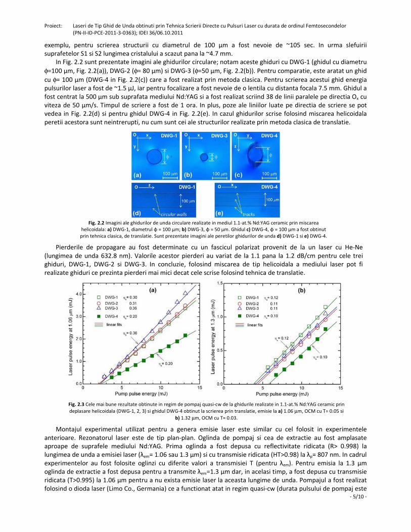
Tehnica de scriere a structurilor tip ghid de unda prin miscarea mediului laser pe o traiectorie de tip helicoidal
este aratata in Fig. 2.1. In cazul metodei clasice, scrierea ghidurilor se face pe directia perpendiculara cu cea in
care se va obtine emisie laser. Ghidurile sunt realizate scriind linii consecutive la diferite adancimi astfel incat
acestea sa incadreze o regiune cu indice de refractie nemodificat, emisia fiind obtinuta in aceasta regiune (Fig.
2.1(a)). Ghidurile realizate prin aceasta metoda pot prezenta pierderi mari; din acest motiv am introdus o noua
tehnica de scriere, folosind miscarea mediului laser pe o traiectorie de tip helicoidal. Astfel, mediul laser este rotit
cu 90°C pe sistemul de translatie Oxyz iar scrierea ghidurilor este realizata pe directia paralela cu cea in care se va
obtine emisie laser, dupa cum se vedea in Fig. 2.1(b). Pozitia mediului laser este variata in planul Oxy printr-o
miscare de rotatie; in acelasi timp se efectueaza si o miscare de translatie in planul Oz. In cazul acestei tehnici
pierderile in structuri sunt micsorate.
Fig. 2.1 a) Tehnica de scriere a ghidurilor de unda prin translatia fasciculului laser, paralel cu directia pe care va fi obtinuta
emisia laser. b) Tehnica de deplasare a mediului laser pe o traiectorie helicoidala, metoda dezvoltata in grupul nostru.
Montajul utilizat pentru realizarea de structuri tip ghid de unda este asemanator cu cel folosit in
experimentele anterioare. Am folosit un mediu 1.1-at.% Nd:YAG ceramic cu lungimea de 5 mm (Baikowski Co.,
Ltd, Japonia), in care au fost scrise trei ghiduri circulare cu diferite diametre (50, 80 si 100 µm). Pentru realizarea
acestor ghiduri am utilizat un obiectiv 10x si NA= 0.30, diametrul fasciculului laser focalizat fiind ~12 µm (in aer).
Energia pulsurilor fs laser a fost de 15 µJ. Durata de scriere a structurilor a scazut dramatic cu aceasta tehnica. De
Proiect: Laseri de Tip Ghid de Unda obtinuti prin Tehnica Scrierii Directe cu Pulsuri Laser cu durata de ordinul Femtosecondelor
(PN-II-ID-PCE-2011-3-0363); IDEI 36/06.10.2011
- 5/10 -
exemplu, pentru scrierea structurii cu diametrul de 100 µm a fost nevoie de ~105 sec. In urma slefuirii
suprafetelor S1 si S2 lungimea cristalului a scazut pana la ~4.7 mm.
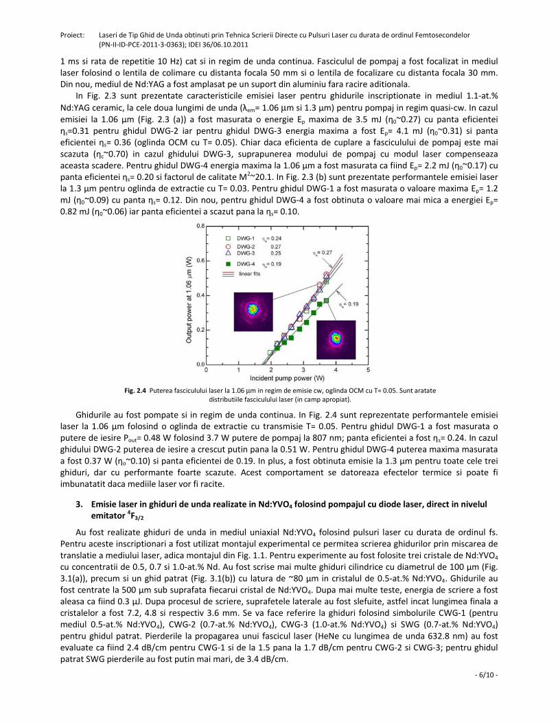
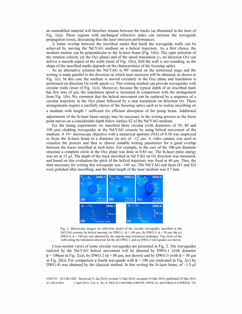
In Fig. 2.2 sunt prezentate imagini ale ghidurilor circulare; notam aceste ghiduri cu DWG-1 (ghidul cu diametru
φ=100 µm, Fig. 2.2(a)), DWG-2 (φ= 80 µm) si DWG-3 (φ=50 µm, Fig. 2.2(b)). Pentru comparatie, este aratat un ghid
cu φ= 100 µm (DWG-4 in Fig. 2.2(c)) care a fost realizat prin metoda clasica. Pentru scrierea acestui ghid energia
pulsurilor laser a fost de ~1.5 µJ, iar pentru focalizare a fost nevoie de o lentila cu distanta focala 7.5 mm. Ghidul a
fost centrat la 500 µm sub suprafata mediului Nd:YAG si a fost realizat scriind 38 de linii paralele pe directia Ox cu
viteza de 50 µm/s. Timpul de scriere a fost de 1 ora. In plus, poze ale liniilor luate pe directia de scriere se pot
vedea in Fig. 2.2(d) si pentru ghidul DWG-4 in Fig. 2.2(e). In cazul ghidurilor scrise folosind miscarea helicoidala
peretii acestora sunt neintrerupti, nu cum sunt cei ale structurilor realizate prin metoda clasica de translatie.
Fig. 2.2 Imagini ale ghidurilor de unda circulare realizate in mediul 1.1-at.% Nd:YAG ceramic prin miscarea
helicoidala: a) DWG-1, diametrul φ = 100 μm; b) DWG-3, φ = 50 μm. Ghidul c) DWG-4, φ = 100 μm a fost obtinut
prin tehnica clasica, de translatie. Sunt prezentate imagini ale peretilor ghidurilor de unda d) DWG-1 si e) DWG-4.
Pierderile de propagare au fost determinate cu un fascicul polarizat provenit de la un laser cu He-Ne
(lungimea de unda 632.8 nm). Valorile acestor pierderi au variat de la 1.1 pana la 1.2 dB/cm pentru cele trei
ghiduri, DWG-1, DWG-2 si DWG-3. In concluzie, folosind miscarea de tip helicoidala a mediului laser pot fi
realizate ghiduri ce prezinta pierderi mai mici decat cele scrise folosind tehnica de translatie.
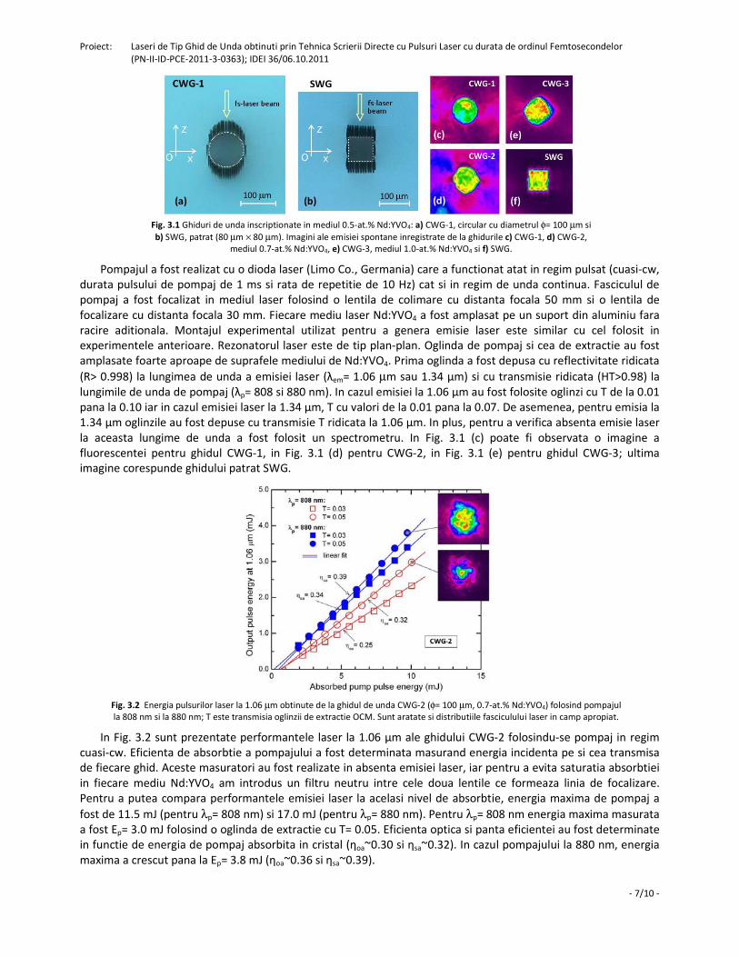
Fig. 2.3 Cele mai bune rezultate obtinute in regim de pompaj quasi-cw de la ghidurile realizate in 1.1-at.% Nd:YAG ceramic prin
deplasare helicoidala (DWG-1, 2, 3) si ghidul DWG-4 obtinut la scrierea prin translatie, emisie la a) 1.06 µm, OCM cu T= 0.05 si
b) 1.32 µm, OCM cu T= 0.03.
Montajul experimental utilizat pentru a genera emisie laser este similar cu cel folosit in experimentele
anterioare. Rezonatorul laser este de tip plan-plan. Oglinda de pompaj si cea de extractie au fost amplasate
aproape de suprafele mediului Nd:YAG. Prima oglinda a fost depusa cu reflectivitate ridicata (R> 0.998) la
lungimea de unda a emisiei laser (λem= 1.06 sau 1.3 µm) si cu transmisie ridicata (HT>0.98) la λp= 807 nm. In cadrul
experimentelor au fost folosite oglinzi cu diferite valori a transmisiei T (pentru λem). Pentru emisia la 1.3 µm
oglinda de extractie a fost depusa pentru a transmite λem=1.3 µm dar, in acelasi timp, a fost depusa cu transmisie
ridicata (T>0.995) la 1.06 µm pentru a nu exista emisie laser la aceasta lungime de unda. Pompajul a fost realizat
folosind o dioda laser (Limo Co., Germania) ce a functionat atat in regim quasi-cw (durata pulsului de pompaj este
Proiect: Laseri de Tip Ghid de Unda obtinuti prin Tehnica Scrierii Directe cu Pulsuri Laser cu durata de ordinul Femtosecondelor
(PN-II-ID-PCE-2011-3-0363); IDEI 36/06.10.2011
- 6/10 -
1 ms si rata de repetitie 10 Hz) cat si in regim de unda continua. Fasciculul de pompaj a fost focalizat in mediul
laser folosind o lentila de colimare cu distanta focala 50 mm si o lentila de focalizare cu distanta focala 30 mm.
Din nou, mediul de Nd:YAG a fost amplasat pe un suport din aluminiu fara racire aditionala.
In Fig. 2.3 sunt prezentate caracteristicile emisiei laser pentru ghidurile inscriptionate in mediul 1.1-at.%
Nd:YAG ceramic, la cele doua lungimi de unda (λem= 1.06 µm si 1.3 µm) pentru pompaj in regim quasi-cw. In cazul
emisiei la 1.06 µm (Fig. 2.3 (a)) a fost masurata o energie Ep maxima de 3.5 mJ (η0~0.27) cu panta eficientei
ηs=0.31 pentru ghidul DWG-2 iar pentru ghidul DWG-3 energia maxima a fost Ep= 4.1 mJ (η0~0.31) si panta
eficientei ηs= 0.36 (oglinda OCM cu T= 0.05). Chiar daca eficienta de cuplare a fasciculului de pompaj este mai
scazuta (ηc~0.70) in cazul ghidului DWG-3, suprapunerea modului de pompaj cu modul laser compenseaza
aceasta scadere. Pentru ghidul DWG-4 energia maxima la 1.06 µm a fost masurata ca fiind Ep= 2.2 mJ (η0~0.17) cu
panta eficientei ηs= 0.20 si factorul de calitate M2~20.1. In Fig. 2.3 (b) sunt prezentate performantele emisiei laser
la 1.3 µm pentru oglinda de extractie cu T= 0.03. Pentru ghidul DWG-1 a fost masurata o valoare maxima Ep= 1.2
mJ (η0~0.09) cu panta ηs= 0.12. Din nou, pentru ghidul DWG-4 a fost obtinuta o valoare mai mica a energiei Ep=
0.82 mJ (η0~0.06) iar panta eficientei a scazut pana la ηs= 0.10.
Fig. 2.4 Puterea fasciculului laser la 1.06 µm in regim de emisie cw, oglinda OCM cu T= 0.05. Sunt aratate
distributiile fasciculului laser (in camp apropiat).
Ghidurile au fost pompate si in regim de unda continua. In Fig. 2.4 sunt reprezentate performantele emisiei
laser la 1.06 µm folosind o oglinda de extractie cu transmisie T= 0.05. Pentru ghidul DWG-1 a fost masurata o
putere de iesire Pout= 0.48 W folosind 3.7 W putere de pompaj la 807 nm; panta eficientei a fost ηs= 0.24. In cazul
ghidului DWG-2 puterea de iesire a crescut putin pana la 0.51 W. Pentru ghidul DWG-4 puterea maxima masurata
a fost 0.37 W (ηo~0.10) si panta eficientei de 0.19. In plus, a fost obtinuta emisie la 1.3 µm pentru toate cele trei
ghiduri, dar cu performante foarte scazute. Acest comportament se datoreaza efectelor termice si poate fi
imbunatatit daca mediile laser vor fi racite.
3. Emisie laser in ghiduri de unda realizate in Nd:YVO4 folosind pompajul cu diode laser, direct in nivelul
emitator 4F3/2
Au fost realizate ghiduri de unda in mediul uniaxial Nd:YVO4 folosind pulsuri laser cu durata de ordinul fs.
Pentru aceste inscriptionari a fost utilizat montajul experimental ce permitea scrierea ghidurilor prin miscarea de
translatie a mediului laser, adica montajul din Fig. 1.1. Pentru experimente au fost folosite trei cristale de Nd:YVO4
cu concentratii de 0.5, 0.7 si 1.0-at.% Nd. Au fost scrise mai multe ghiduri cilindrice cu diametrul de 100 µm (Fig.
3.1(a)), precum si un ghid patrat (Fig. 3.1(b)) cu latura de ~80 µm in cristalul de 0.5-at.% Nd:YVO4. Ghidurile au
fost centrate la 500 µm sub suprafata fiecarui cristal de Nd:YVO4. Dupa mai multe teste, energia de scriere a fost
aleasa ca fiind 0.3 µJ. Dupa procesul de scriere, suprafetele laterale au fost slefuite, astfel incat lungimea finala a
cristalelor a fost 7.2, 4.8 si respectiv 3.6 mm. Se va face referire la ghiduri folosind simbolurile CWG-1 (pentru
mediul 0.5-at.% Nd:YVO4), CWG-2 (0.7-at.% Nd:YVO4), CWG-3 (1.0-at.% Nd:YVO4) si SWG (0.7-at.% Nd:YVO4)
pentru ghidul patrat. Pierderile la propagarea unui fascicul laser (HeNe cu lungimea de unda 632.8 nm) au fost
evaluate ca fiind 2.4 dB/cm pentru CWG-1 si de la 1.5 pana la 1.7 dB/cm pentru CWG-2 si CWG-3; pentru ghidul
patrat SWG pierderile au fost putin mai mari, de 3.4 dB/cm.
Proiect: Laseri de Tip Ghid de Unda obtinuti prin Tehnica Scrierii Directe cu Pulsuri Laser cu durata de ordinul Femtosecondelor
(PN-II-ID-PCE-2011-3-0363); IDEI 36/06.10.2011
- 7/10 -
Fig. 3.1 Ghiduri de unda inscriptionate in mediul 0.5-at.% Nd:YVO4: a) CWG-1, circular cu diametrul φ= 100 µm si
b) SWG, patrat (80 µm × 80 µm). Imagini ale emisiei spontane inregistrate de la ghidurile c) CWG-1, d) CWG-2,
mediul 0.7-at.% Nd:YVO4, e) CWG-3, mediul 1.0-at.% Nd:YVO4 si f) SWG.
Pompajul a fost realizat cu o dioda laser (Limo Co., Germania) care a functionat atat in regim pulsat (cuasi-cw,
durata pulsului de pompaj de 1 ms si rata de repetitie de 10 Hz) cat si in regim de unda continua. Fasciculul de
pompaj a fost focalizat in mediul laser folosind o lentila de colimare cu distanta focala 50 mm si o lentila de
focalizare cu distanta focala 30 mm. Fiecare mediu laser Nd:YVO4 a fost amplasat pe un suport din aluminiu fara
racire aditionala. Montajul experimental utilizat pentru a genera emisie laser este similar cu cel folosit in
experimentele anterioare. Rezonatorul laser este de tip plan-plan. Oglinda de pompaj si cea de extractie au fost
amplasate foarte aproape de suprafele mediului de Nd:YVO4. Prima oglinda a fost depusa cu reflectivitate ridicata
(R> 0.998) la lungimea de unda a emisiei laser (λem= 1.06 µm sau 1.34 µm) si cu transmisie ridicata (HT>0.98) la
lungimile de unda de pompaj (λp= 808 si 880 nm). In cazul emisiei la 1.06 µm au fost folosite oglinzi cu T de la 0.01
pana la 0.10 iar in cazul emisiei laser la 1.34 µm, T cu valori de la 0.01 pana la 0.07. De asemenea, pentru emisia la
1.34 µm oglinzile au fost depuse cu transmisie T ridicata la 1.06 µm. In plus, pentru a verifica absenta emisie laser
la aceasta lungime de unda a fost folosit un spectrometru. In Fig. 3.1 (c) poate fi observata o imagine a
fluorescentei pentru ghidul CWG-1, in Fig. 3.1 (d) pentru CWG-2, in Fig. 3.1 (e) pentru ghidul CWG-3; ultima
imagine corespunde ghidului patrat SWG.
Fig. 3.2 Energia pulsurilor laser la 1.06 µm obtinute de la ghidul de unda CWG-2 (φ= 100 µm, 0.7-at.% Nd:YVO4) folosind pompajul
la 808 nm si la 880 nm; T este transmisia oglinzii de extractie OCM. Sunt aratate si distributiile fasciculului laser in camp apropiat.
In Fig. 3.2 sunt prezentate performantele laser la 1.06 µm ale ghidului CWG-2 folosindu-se pompaj in regim
cuasi-cw. Eficienta de absorbtie a pompajului a fost determinata masurand energia incidenta pe si cea transmisa
de fiecare ghid. Aceste masuratori au fost realizate in absenta emisiei laser, iar pentru a evita saturatia absorbtiei
in fiecare mediu Nd:YVO4 am introdus un filtru neutru intre cele doua lentile ce formeaza linia de focalizare.
Pentru a putea compara performantele emisiei laser la acelasi nivel de absorbtie, energia maxima de pompaj a
fost de 11.5 mJ (pentru λp= 808 nm) si 17.0 mJ (pentru λp= 880 nm). Pentru λp= 808 nm energia maxima masurata
a fost Ep= 3.0 mJ folosind o oglinda de extractie cu T= 0.05. Eficienta optica si panta eficientei au fost determinate
in functie de energia de pompaj absorbita in cristal (ηoa~0.30 si ηsa~0.32). In cazul pompajului la 880 nm, energia
maxima a crescut pana la Ep= 3.8 mJ (ηoa~0.36 si ηsa~0.39).
Proiect: Laseri de Tip Ghid de Unda obtinuti prin Tehnica Scrierii Directe cu Pulsuri Laser cu durata de ordinul Femtosecondelor
(PN-II-ID-PCE-2011-3-0363); IDEI 36/06.10.2011
- 8/10 -
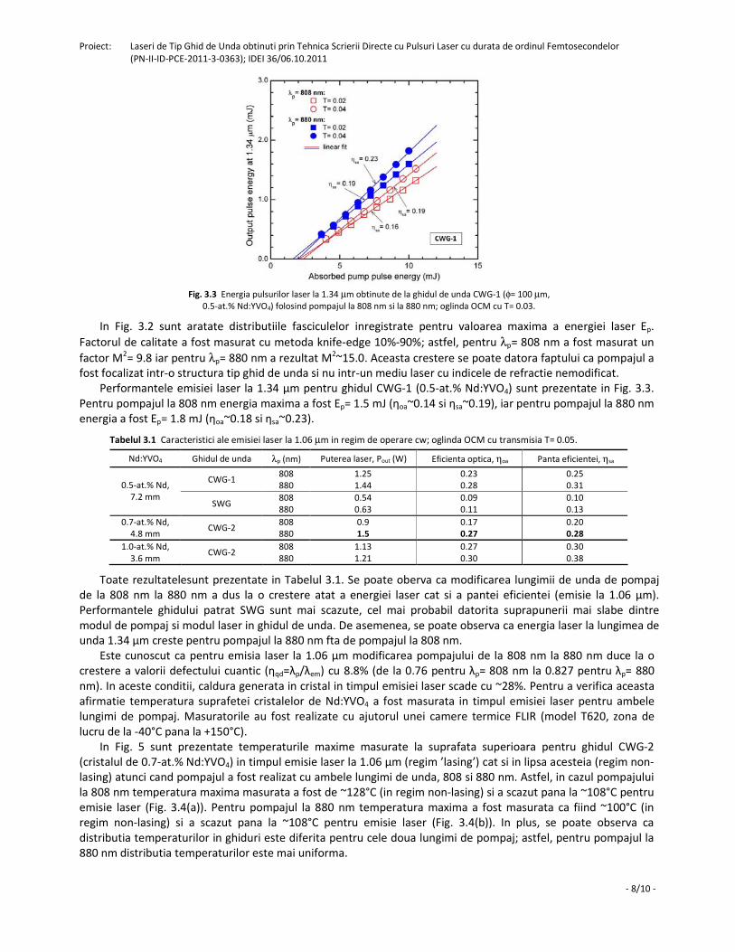
Fig. 3.3 Energia pulsurilor laser la 1.34 µm obtinute de la ghidul de unda CWG-1 (φ= 100 µm,
0.5-at.% Nd:YVO4) folosind pompajul la 808 nm si la 880 nm; oglinda OCM cu T= 0.03.
In Fig. 3.2 sunt aratate distributiile fasciculelor inregistrate pentru valoarea maxima a energiei laser Ep.
Factorul de calitate a fost masurat cu metoda knife-edge 10%-90%; astfel, pentru λp= 808 nm a fost masurat un
factor M2= 9.8 iar pentru λp= 880 nm a rezultat M
2~15.0. Aceasta crestere se poate datora faptului ca pompajul a
fost focalizat intr-o structura tip ghid de unda si nu intr-un mediu laser cu indicele de refractie nemodificat.
Performantele emisiei laser la 1.34 µm pentru ghidul CWG-1 (0.5-at.% Nd:YVO4) sunt prezentate in Fig. 3.3.
Pentru pompajul la 808 nm energia maxima a fost Ep= 1.5 mJ (ηoa~0.14 si ηsa~0.19), iar pentru pompajul la 880 nm
energia a fost Ep= 1.8 mJ (ηoa~0.18 si ηsa~0.23).
Tabelul 3.1 Caracteristici ale emisiei laser la 1.06 µm in regim de operare cw; oglinda OCM cu transmisia T= 0.05.
Nd:YVO4 Ghidul de unda λp (nm) Puterea laser, Pout (W) Eficienta optica, ηoa Panta eficientei, ηsa
CWG-1 808
880
1.25
1.44
0.23
0.28
0.25
0.31 0.5-at.% Nd,
7.2 mm SWG
808
880
0.54
0.63
0.09
0.11
0.10
0.13
0.7-at.% Nd,
4.8 mm CWG-2
808
880
0.9
1.5
0.17
0.27
0.20
0.28
1.0-at.% Nd,
3.6 mm CWG-2
808
880
1.13
1.21
0.27
0.30
0.30
0.38
Toate rezultatelesunt prezentate in Tabelul 3.1. Se poate oberva ca modificarea lungimii de unda de pompaj
de la 808 nm la 880 nm a dus la o crestere atat a energiei laser cat si a pantei eficientei (emisie la 1.06 µm).
Performantele ghidului patrat SWG sunt mai scazute, cel mai probabil datorita suprapunerii mai slabe dintre
modul de pompaj si modul laser in ghidul de unda. De asemenea, se poate observa ca energia laser la lungimea de
unda 1.34 µm creste pentru pompajul la 880 nm fta de pompajul la 808 nm.
Este cunoscut ca pentru emisia laser la 1.06 µm modificarea pompajului de la 808 nm la 880 nm duce la o
crestere a valorii defectului cuantic (ηqd=λp/λem) cu 8.8% (de la 0.76 pentru λp= 808 nm la 0.827 pentru λp= 880
nm). In aceste conditii, caldura generata in cristal in timpul emisiei laser scade cu ~28%. Pentru a verifica aceasta
afirmatie temperatura suprafetei cristalelor de Nd:YVO4 a fost masurata in timpul emisiei laser pentru ambele
lungimi de pompaj. Masuratorile au fost realizate cu ajutorul unei camere termice FLIR (model T620, zona de
lucru de la -40°C pana la +150°C).
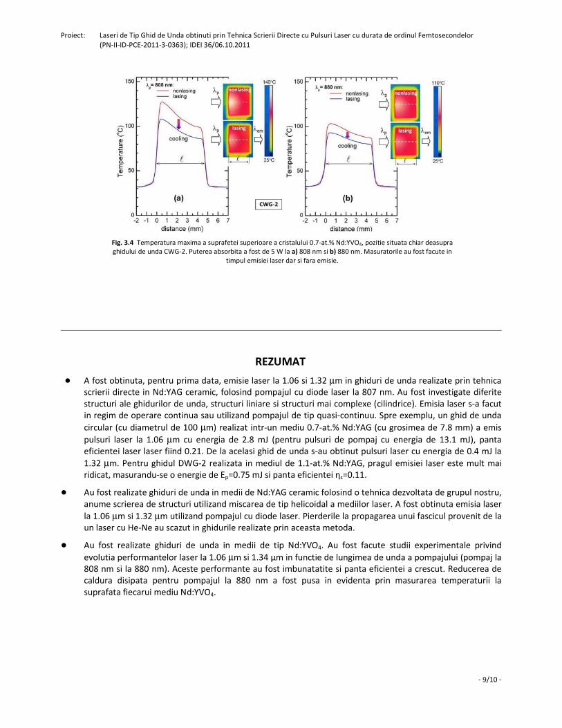
In Fig. 5 sunt prezentate temperaturile maxime masurate la suprafata superioara pentru ghidul CWG-2
(cristalul de 0.7-at.% Nd:YVO4) in timpul emisie laser la 1.06 µm (regim ’lasing’) cat si in lipsa acesteia (regim non-
lasing) atunci cand pompajul a fost realizat cu ambele lungimi de unda, 808 si 880 nm. Astfel, in cazul pompajului
la 808 nm temperatura maxima masurata a fost de ~128°C (in regim non-lasing) si a scazut pana la ~108°C pentru
emisie laser (Fig. 3.4(a)). Pentru pompajul la 880 nm temperatura maxima a fost masurata ca fiind ~100°C (in
regim non-lasing) si a scazut pana la ~108°C pentru emisie laser (Fig. 3.4(b)). In plus, se poate observa ca
distributia temperaturilor in ghiduri este diferita pentru cele doua lungimi de pompaj; astfel, pentru pompajul la
880 nm distributia temperaturilor este mai uniforma.
Proiect: Laseri de Tip Ghid de Unda obtinuti prin Tehnica Scrierii Directe cu Pulsuri Laser cu durata de ordinul Femtosecondelor
(PN-II-ID-PCE-2011-3-0363); IDEI 36/06.10.2011
- 9/10 -
Fig. 3.4 Temperatura maxima a suprafetei superioare a cristalului 0.7-at.% Nd:YVO4, pozitie situata chiar deasupra
ghidului de unda CWG-2. Puterea absorbita a fost de 5 W la a) 808 nm si b) 880 nm. Masuratorile au fost facute in
timpul emisiei laser dar si fara emisie.
REZUMAT
● A fost obtinuta, pentru prima data, emisie laser la 1.06 si 1.32 µm in ghiduri de unda realizate prin tehnica
scrierii directe in Nd:YAG ceramic, folosind pompajul cu diode laser la 807 nm. Au fost investigate diferite
structuri ale ghidurilor de unda, structuri liniare si structuri mai complexe (cilindrice). Emisia laser s-a facut
in regim de operare continua sau utilizand pompajul de tip quasi-continuu. Spre exemplu, un ghid de unda
circular (cu diametrul de 100 µm) realizat intr-un mediu 0.7-at.% Nd:YAG (cu grosimea de 7.8 mm) a emis
pulsuri laser la 1.06 µm cu energia de 2.8 mJ (pentru pulsuri de pompaj cu energia de 13.1 mJ), panta
eficientei laser laser fiind 0.21. De la acelasi ghid de unda s-au obtinut pulsuri laser cu energia de 0.4 mJ la
1.32 µm. Pentru ghidul DWG-2 realizata in mediul de 1.1-at.% Nd:YAG, pragul emisiei laser este mult mai
ridicat, masurandu-se o energie de Ep=0.75 mJ si panta eficientei ηs=0.11.
● Au fost realizate ghiduri de unda in medii de Nd:YAG ceramic folosind o tehnica dezvoltata de grupul nostru,
anume scrierea de structuri utilizand miscarea de tip helicoidal a mediilor laser. A fost obtinuta emisia laser
la 1.06 µm si 1.32 µm utilizand pompajul cu diode laser. Pierderile la propagarea unui fascicul provenit de la
un laser cu He-Ne au scazut in ghidurile realizate prin aceasta metoda.
● Au fost realizate ghiduri de unda in medii de tip Nd:YVO4. Au fost facute studii experimentale privind
evolutia performantelor laser la 1.06 µm si 1.34 µm in functie de lungimea de unda a pompajului (pompaj la
808 nm si la 880 nm). Aceste performante au fost imbunatatite si panta eficientei a crescut. Reducerea de
caldura disipata pentru pompajul la 880 nm a fost pusa in evidenta prin masurarea temperaturii la
suprafata fiecarui mediu Nd:YVO4.
Proiect: Laseri de Tip Ghid de Unda obtinuti prin Tehnica Scrierii Directe cu Pulsuri Laser cu durata de ordinul Femtosecondelor
(PN-II-ID-PCE-2011-3-0363); IDEI 36/06.10.2011
- 10/10 -
DISEMINARE
● Rezultatele obtinute in aceasta etapa au fost publicate in 4 (patru) articole ISI.
1. G. Salamu, F. Jipa, M. Zamfirescu, and N. Pavel, “Laser emission from diode-pumped Nd:YAG ceramic waveguide
lasers realized by direct femtosecond-laser writing technique,” Opt. Express 22 (5), 5177-5182 (2014).
http://dx.doi.org/10.1364/OE.22.005177
Factor de impact pe anul 2013: 3.525
2. G. Salamu, F. Jipa, M. Zamfirescu, and N. Pavel, “Cladding waveguides realized in Nd:YAG ceramic by direct
femtosecond-laser writing with a helical movement technique,” Opt. Mater. Express 4 (4), 790-797 (2014).
http://dx.doi.org/10.1364/OME.4.000790
Factor de impact pe anul 2013: 2.923
3. N. Pavel, G. Salamu, F. Voicu, F. Jipa, and M. Zamfirescu, “Cladding waveguides realized in Nd:YAG laser media by
direct writing with a femtosecond-laser beam,” Proceedings of the Romanian Academy Series A - Mathematics
Physics Technical Sciences Information Science 15 (2), 151-158 (2014).
Factor de impact pe anul 2013: 1.115
4. N. Pavel, G. Salamu, F. Jipa, and M. Zamfirescu, “Diode-laser pumping into the emitting level for efficient lasing of
depressed cladding waveguides realized in Nd:YVO4 by the direct femtosecond-laser writing technique,” Opt.
Express 22 (19), 23057-23065 (2014).
http://dx.doi.org/10.1364/OE.22.023057
Factor de impact pe anul 2013: 3.525
● Au fost prezentate comunicari la 5 (cinci) conferinte cu participare internationala.
1. G. Salamu, F. Jipa, M. Zamfirescu, and N. Pavel, “Laser Emission from Nd:YAG Laser Waveguides Realized by
Femtosecond-Laser Writing Techniques,” 2014 Photonics Europe SPIE Conference, 14-17 April 2014, Brussels,
Belgium; paper number: 9135-52 (prezentare orala).
2. N. Pavel, G. Salamu, F. Voicu, T. Dascalu, F. Jipa, and M. Zamfirescu, “Waveguides Fabricated in Nd:YAG by Direct fs-
Laser Writing - Realization and Laser Emission under Diode-Laser Pumping,” The 14th International Balkan
Workshop on Applied Physics, July 2-4, 2014, Constanta, Romania, presentation S2-L07, Book of Abstracts p. 106
(prezentare invitata).
3. N. Pavel, G. Salamu, F. Jipa, M. Zamfirescu, F. Voicu, and T. Dascalu, ”Efficient laser emission in diode-pumped
Nd:YAG cladding waveguides fabricated by direct writing with a helical movement technique,” 6th EPS-QEOD
EUROPHOTON CONFERENCE, Solid State, Fibre, and Waveguide Coherent Light Sources, 24-29 August, 2014,
Neuchâtel, Switzerland, presentation TuP-T2-P-02; Europhysics Conference Abstract Vol. 38 E; ISBN 2-914771-89-4.
(prezentare poster).
4. G. Salamu, F. Jipa, M. Zamfirescu, F. Voicu, and N. Pavel, “Laser emission from diode-pumped Nd:YAG waveguide
lasers realized by femtosecond-writing technique,” 5th International Student Conference on Photonics, Orastie,
Romania, 23-26 September 2014; presentation O.02 (prezentare orala).
Nota: Aceasta comunicare a fost premiata cu diploma "Best Oral Presentation - Second Place".
5. N. Pavel, G. Salamu, F. Jipa, and M. Zamfirescu, “Efficient Laser Emission under 880-nm Diode-Laser Pumping of
Cladding Waveguides Inscribed in Nd:YVO4 by Femtosecond-Laser Writing Technique,“ Advanced Solid State Lasers
(ASSL) Congress, 16-21 November 2014, Shanghai, China, presentation ATu2A.26 (prezentare poster).
● Prezentarea orala sustinuta la 2014 Photonics SPIE Conference (14-17 Aprilie 2014, Brussels, Belgia)
a fost publicata intr-un proceeding SPIE.
1. G. Salamu, F. Voicu, F. Jipa, M. Zamfirescu, T. Dascalu, and N. Pavel, "Laser emission from diode-pumped Nd:YAG
cladding waveguides obtained by direct writing with a femtosecond-laser beam," Proc. SPIE 9135, Laser Sources and
Applications II, 91351F (May 1, 2014); doi:10.1117/12.2052250; http://dx.doi.org/10.1117/12.2052250
Laser emission from diode-pumped Nd:YAG ceramic waveguide lasers realized by direct
femtosecond-laser writing technique Gabriela Salamu,1,3,4 Florin Jipa,2,3 Marian Zamfirescu,2 and Nicolaie Pavel1,*
1Laboratory of Solid-State Quantum Electronics, National Institute for Laser, Plasma and Radiation Physics, Bucharest R-077125, Romania
2Solid-State Laser Laboratory, Laser Department, National Institute for Laser, Plasma and Radiation Physics, Bucharest R-077125, Romania
3Doctoral School of Physics, University of Bucharest, Romania [email protected]
Abstract: We report on realization of buried waveguides in Nd:YAG ceramic media by direct femtosecond-laser writing technique and investigate the waveguides laser emission characteristics under the pump with fiber-coupled diode lasers. Laser pulses at 1.06 μm with energy of 2.8 mJ for the pump with pulses of 13.1-mJ energy and continuous-wave output power of 0.49 W with overall optical efficiency of 0.13 were obtained from a 100-μm diameter circular cladding waveguide realized in a 0.7-at.% Nd:YAG ceramic. A circular waveguide of 50-μm diameter yielded laser pulses at 1.3 μm with 1.2-mJ energy.
©2014 Optical Society of America
OCIS codes: (140.3580) Lasers, solid-state; (140.3530) Lasers, neodymium; (230.7380) Waveguides, channeled; (130.3990) Micro-optical devices.
References and links
1. C. Grivas, “Optically pumped planar waveguide lasers, Part I: Fundamentals and fabrication techniques,” Prog. Quantum Electron. 35(6), 159–239 (2011).
2. F. Chen and J. R. V’azquez de Aldana, “Optical waveguides in crystalline dielectric materials produced by femtosecond-laser micromachining,” Laser Photonics Rev. doi:10.1002/lpor.201300025 (2013).
3. K. M. Davis, K. Miura, N. Sugimoto, and K. Hirao, “Writing waveguides in glass with a femtosecond laser,” Opt. Lett. 21(21), 1729–1731 (1996).
4. A. Ródenas, G. A. Torchia, G. Lifante, E. Cantelar, J. Lamela, F. Jaque, L. Roso, and D. Jaque, “Refractive index change mechanisms in femtosecond laser written ceramic Nd:YAG waveguides: micro-spectroscopy experiments and beam propagation calculations,” Appl. Phys. B 95(1), 85–96 (2009).
5. T. Calmano, J. Siebenmorgen, O. Hellmig, K. Petermann, and G. Huber, “Nd:YAG waveguide laser with 1.3 W output power, fabricated by direct femtosecond laser writing,” Appl. Phys. B 100(1), 131–135 (2010).
6. G. A. Torchia, A. Rodenas, A. Benayas, E. Cantelar, L. Roso, and D. Jaque, “Highly efficient laser action in femtosecond-written Nd:yttrium aluminum garnet ceramic waveguides,” Appl. Phys. Lett. 92(11), 111103 (2008).
7. Y. Tan, A. Rodenas, F. Chen, R. R. Thomson, A. K. Kar, D. Jaque, and Q. M. Lu, “70% slope efficiency from an ultrafast laser-written Nd:GdVO4 channel waveguide laser,” Opt. Express 18(24), 24994–24999 (2010).
8. J. Siebenmorgen, T. Calmano, K. Petermann, and G. Huber, “Highly efficient Yb:YAG channel waveguide laser written with a femtosecond-laser,” Opt. Express 18(15), 16035–16041 (2010).
9. S. Müller, T. Calmano, P. Metz, N.-O. Hansen, C. Kränkel, and G. Huber, “Femtosecond-laser-written diode-pumped Pr:LiYF4 waveguide laser,” Opt. Lett. 37(24), 5223–5225 (2012).
10. A. G. Okhrimchuk, A. V. Shestakov, I. Khrushchev, and J. Mitchell, “Depressed cladding, buried waveguide laser formed in a YAG:Nd3+ crystal by femtosecond laser writing,” Opt. Lett. 30(17), 2248–2250 (2005).
11. A. Okhrimchuk, V. Mezentsev, A. Shestakov, and I. Bennion, “Low loss depressed cladding waveguide inscribed in YAG:Nd single crystal by femtosecond laser pulses,” Opt. Express 20(4), 3832–3843 (2012).
12. H. Liu, Y. Jia, J. R. Vázquez de Aldana, D. Jaque, and F. Chen, “Femtosecond laser inscribed cladding waveguides in Nd:YAG ceramics: Fabrication, fluorescence imaging and laser performance,” Opt. Express 20(17), 18620–18629 (2012).
13. Y. Ren, G. Brown, A. Ródenas, S. Beecher, F. Chen, and A. K. Kar, “Mid-infrared waveguide lasers in rare-earth-doped YAG,” Opt. Lett. 37(16), 3339–3341 (2012).
#204060 - $15.00 USD Received 6 Jan 2014; revised 10 Feb 2014; accepted 16 Feb 2014; published 27 Feb 2014(C) 2014 OSA 10 March 2014 | Vol. 22, No. 5 | DOI:10.1364/OE.22.005177 | OPTICS EXPRESS 5177
14. H. Liu, F. Chen, J. R. Vázquez de Aldana, and D. Jaque, “Femtosecond-laser inscribed double-cladding waveguides in Nd:YAG crystal: a promising prototype for integrated lasers,” Opt. Lett. 38(17), 3294–3297 (2013).
15. T. Calmano, J. Siebenmorgen, A.-G. Paschke, C. Fiebig, K. Paschke, G. Erbert, K. Petermann, and G. Huber, “Diode pumped high power operation of a femtosecond laser inscribed Yb:YAG waveguide laser,” Opt. Mater. Express 1(3), 428–433 (2011).
16. N. Pavel, G. Salamu, F. Voicu, F. Jipa, M. Zamfirescu, and T. Dascalu, “Efficient laser emission in diode-pumped Nd:YAG buried waveguides realized by direct femtosecond-laser writing,” Laser Phys. Lett. 10(9), 095802 (2013).
17. N. Pavel, V. Lupei, and T. Taira, “1.34-µm efficient laser emission in highly-doped Nd:YAG under 885-nm diode pumping,” Opt. Express 13(20), 7948–7953 (2005).
1. Introduction
The direct femtosecond (fs)-laser writing technique is now recognized as a powerful tool for realizing waveguides in various transparent optical materials [1,2]. Because of non-linear absorption processes, a focalized fs-laser pulse can produce modifications at micro or sub micrometric scales, thus inducing changes of the refractive index inside the material. There are a several techniques that can be used for inscribing waveguides [2]. One of these methods is specific to glasses and LiNbO3. In this case melting and re-solidification of the irradiated volume provides a track with an increased index of refraction compared with that of the medium; the track is used itself for light propagation [3].
Another writing method can even damage the material inside the irradiated volume and by stress causes a decrease of the refractive index in the adjacent region; this time the light is guided in between two such tracks [4]. Two-line (or two-wall) waveguides were realized in various laser materials, like Nd:Y3Al5O12 (Nd:YAG) single crystal [5] and ceramic [6], Nd-vanadates [7], Yb:YAG single crystal [8] or Pr:YLiF4 (Pr:YLF) [9]. Efficient laser emission was realized from such waveguides. For example, an output power of 1.3 W at 1.06 μm was obtained from a Nd:YAG waveguide for the pump with 2.25 W at 808 nm [5], and the pump with 1.2 W at 941 nm yielded 0.8 W at 1.03 μm from an Yb:YAG waveguide [8]. In the experiments a continuous-wave (cw) tunable Ti:Sapphire laser was used as the pump source.
A more complex procedure that implies writing of many tracks around a defined perimeter was proposed by Okhrimchuk et al. [10]. This method allows obtaining of buried depressed cladding waveguides with different tubular shapes and sizes, thus enabling propagation of a randomly polarized beam (and not only of a linearly-polarized light like in the case of the two-wall waveguides). Waveguides with rectangular and nearly circular cross-sections were realized in Nd:YAG single crystals [10, 11], with circular, hexagonal and trapezoidal shapes in Nd:YAG ceramic [12], rhombic in Pr:YLF [9] crystal or circular in Tm:YAG ceramic [13]. Furthermore, it was shown recently that this technique is promising for realizing integrated lasers consisting of double-cladding waveguides [14].
Laser emission under the pump with diode lasers of waveguides realized by fs-laser writing was reported in a few papers [9–11, 15]. Visible orange and deep-red laser lights with output powers of few tens of mW were achieved in Pr:YLF from a rhombic cladding waveguide under the pump at 444 nm with an array diode laser [9]. A nearly-circular cladding waveguide realized in Nd:YAG single crystal yielded 180-mW output power at 1.06 μm using the pump at 808 nm with a fiber-coupled diode laser [11]. Output power of 2.35 W at 1.03 μm was obtained from an Yb:YAG single crystal, two-wall waveguide pumped with a distributed-Bragg-reflector tapered diode laser [15]. Our group has reported recently laser emission at 1.06 and 1.3 μm in buried waveguides realized in Nd:YAG single crystal, employing fiber-coupled diode lasers for pumping [16]. Laser pulses with 1.4 mJ energy (Ep) at 1.06 μm and with Ep = 0.4 mJ at 1.3 μm were achieved from a circular waveguide with 110-μm diameter.
In this work we report our latest results on realization of buried two-wall type and circular cladding waveguide in Nd:YAG ceramic media by direct fs-laser writing method, and on laser emission characteristics obtained under the pump at 807 nm with fiber-coupled diode lasers. Laser pulses at 1.06 μm with Ep = 2.8 mJ and cw output power of 0.49 W were achieved from a circular cladding waveguide with 100-μm diameter that was inscribed in a 0.7-at.% Nd:YAG. The best result at 1.3 μm, i.e. laser pulses with Ep = 1.2 mJ, was obtained from a
#204060 - $15.00 USD Received 6 Jan 2014; revised 10 Feb 2014; accepted 16 Feb 2014; published 27 Feb 2014(C) 2014 OSA 10 March 2014 | Vol. 22, No. 5 | DOI:10.1364/OE.22.005177 | OPTICS EXPRESS 5178
cladding waveguide with diameter of 50 μm. To the best of our knowledge these are the first results on laser emission obtained under the pump with fiber-coupled diode lasers from waveguides realized by direct fs-laser writing technique in Nd:YAG ceramic media.
2. Waveguides fabrication
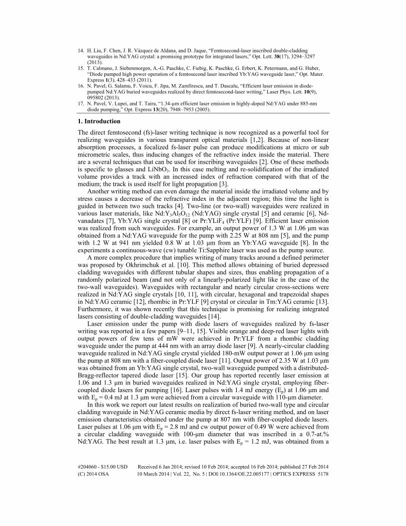
The experimental set-up used for writing tracks in Nd:YAG ceramic media is shown in Fig. 1. A chirped pulsed amplified system (Clark CPA-2101) delivered laser pulses at 775 nm with duration of 200 fs, at 2-kHz repetition rate and energy up to 0.6 mJ. The fs-laser pulse energy was controlled by a combination of half-wave plate (λ/2), a polarizer (P) and calibrated neutral filters (F). An achromatic lens (L) with 7.5-mm focal length and numerical aperture NA = 0.3 was used to focus the beam to a diameter (in air) of ~5.0 μm. The laser media were two Nd:YAG ceramics (Baikowski Co. Ltd., Japan) with 0.7-at.% and 1.1-at.% Nd doping level. Each medium was placed on a motorized translation stage that allowed controllable movement on all directions. Tracks were inscribed on Ox direction at 50-μm/s speed of the translation stage, and the writing process was monitored with a video camera. The end faces of Nd:YAG were polished after writing; finally, each medium length was ~7.8 mm.
Fig. 1. The experimental set-up used for inscribing tracks in the Nd:YAG ceramic media is presented. λ/2: half-wave plate, P: polarizer, F: filter; HRM: high-reflectivity mirror; L: lens.
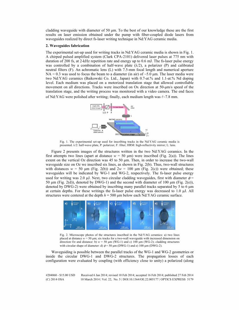
Figure 2 presents images of the structures written in the two Nd:YAG ceramics. In the first attempts two lines (apart at distance w = 50 μm) were inscribed (Fig. 2(a)). The lines extent on the vertical Oz direction was 45 to 50 μm. Then, in order to increase the two-wall waveguide size on Oz we inscribed six lines, as shown in Fig. 2(b). Thus, two-wall structures with distances w = 50 μm (Fig. 2(b)) and 2w = 100 μm (Fig. 2(c)) were obtained; these waveguides will be indicated by WG-1 and WG-2, respectively. The fs-laser pulse energy used for writing was 2.0 μJ. Next, two circular cladding waveguides, first with diameter φ = 50 μm (Fig. 2(d)), denoted by DWG-1) and the second with diameter of 100 μm (Fig. 2(e)), denoted by DWG-2) were obtained by inscribing many parallel tracks separated by 5 to 6 μm at certain depths. For these writings the fs-laser pulse energy was decreased to 1.0 μJ. All structures were centered at the depth h = 500 μm below each Nd:YAG ceramic surface.
Fig. 2. Microscope photos of the structures inscribed in the Nd:YAG ceramics: a) two lines placed at distance w = 50 μm; six tracks for a two-wall waveguide with increased dimension on direction Oz and distance: b) w = 50 μm (WG-1) and c) 100 μm (WG-2); cladding structures with circular shape of diameter: d) φ = 50 μm (DWG-1) and e) 100 μm (DWG-2).
Waveguiding is possible between the parallel tracks of the WG-1 and WG-2 geometries or inside the circular DWG-1 and DWG-2 structures. The propagation losses of each configuration were evaluated by coupling (with efficiency close to unity) a polarized (along
#204060 - $15.00 USD Received 6 Jan 2014; revised 10 Feb 2014; accepted 16 Feb 2014; published 27 Feb 2014(C) 2014 OSA 10 March 2014 | Vol. 22, No. 5 | DOI:10.1364/OE.22.005177 | OPTICS EXPRESS 5179
Oz axis) HeNe laser beam into every structure and by measuring the power of the transmitted light. The measurements concluded that, regardless of the Nd:YAG ceramic media, the propagation losses at 632.8 nm were around 0.5 dB/cm for the WG-1 waveguides and in the range of 0.6 to 0.7 dB/cm for the WG-2 waveguides. In the case of the circular structures losses were 1.0 to 1.2 dB/cm for DWG-1 and a little higher, 1.5 to 1.8 dB/cm for the DWG-2 waveguides. These numbers compare well with those reported for two-wall waveguides inscribed in Nd:YAG single crystals (1.6 dB/cm at 1063 nm) [5] and in Nd:YAG ceramic (0.6 dB/cm at 748 nm) [6], or with losses of the various depressed cladding waveguides realized in Nd:YAG ceramic (0.8 to 1.4 dB/cm at 632.8 nm) [12].
3. Laser emission results and discussion
For the laser experiments each uncoated Nd:YAG ceramic was positioned in a linear plane-plane resonator. The rear high-reflectivity mirror (HRM) was coated HR (reflectivity, R> 0.998) at the laser emission wavelength (λem) of 1.06 or 1.3 μm and with high transmission, HT (transmission, T> 0.98) at the pump wavelength (λp) of 807 nm. Various output coupling mirrors (OCM) with different T at λem were used. The mirrors were set very close of Nd:YAG, and each medium was placed on an aluminum plate without any additional cooling. The optical pumping was made at 807 nm with a fiber-coupled diode laser (LIMO Co., Germany) that was operated in quasi-cw mode (pump pulse duration of 1 ms at 10 Hz repetition rate), as well as in cw regime. The fiber end (100-μm diameter and NA = 0.22) was imaged into each Nd:YAG ceramic using a collimating lens of 50-mm focal length and a focusing lens of 30-mm focal length. Furthermore, a polarizer was placed between these lenses for the pump of the waveguides WG-1 and WG-2 with a linearly-polarized (parallel to the Oz axis) beam.
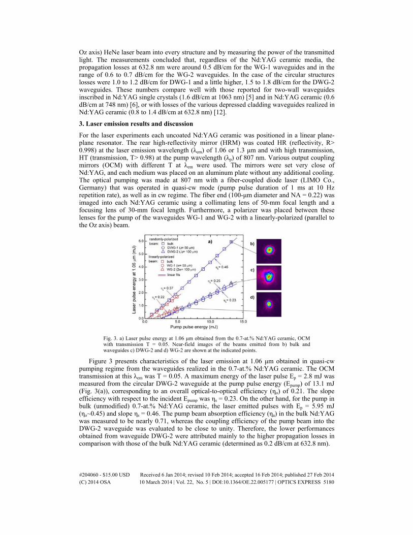
Fig. 3. a) Laser pulse energy at 1.06 μm obtained from the 0.7-at.% Nd:YAG ceramic, OCM with transmission T = 0.05. Near-field images of the beams emitted from b) bulk and waveguides c) DWG-2 and d) WG-2 are shown at the indicated points.
Figure 3 presents characteristics of the laser emission at 1.06 μm obtained in quasi-cw pumping regime from the waveguides realized in the 0.7-at.% Nd:YAG ceramic. The OCM transmission at this λem was T = 0.05. A maximum energy of the laser pulse Ep = 2.8 mJ was measured from the circular DWG-2 waveguide at the pump pulse energy (Epump) of 13.1 mJ (Fig. 3(a)), corresponding to an overall optical-to-optical efficiency (ηo) of 0.21. The slope efficiency with respect to the incident Epump was ηs = 0.23. On the other hand, for the pump in bulk (unmodified) 0.7-at.% Nd:YAG ceramic, the laser emitted pulses with Ep = 5.95 mJ (ηo~0.45) and slope ηs = 0.46. The pump beam absorption efficiency (ηa) in the bulk Nd:YAG was measured to be nearly 0.71, whereas the coupling efficiency of the pump beam into the DWG-2 waveguide was evaluated to be close to unity. Therefore, the lower performances obtained from waveguide DWG-2 were attributed mainly to the higher propagation losses in comparison with those of the bulk Nd:YAG ceramic (determined as 0.2 dB/cm at 632.8 nm).
#204060 - $15.00 USD Received 6 Jan 2014; revised 10 Feb 2014; accepted 16 Feb 2014; published 27 Feb 2014(C) 2014 OSA 10 March 2014 | Vol. 22, No. 5 | DOI:10.1364/OE.22.005177 | OPTICS EXPRESS 5180
The two-wall type WG-2 waveguide delivered a linearly-polarized beam with maximum energy Ep = 0.8 mJ for Epump = 4.8 mJ (i.e. ηo~0.17) and slope ηs = 0.22. Figure 3 shows also the laser beam near-field images that were recorded with a Spiricon camera (model SP620U, 190-1100 nm spectral range). In general, the beams were stable in time and present nearly symmetrical shapes. The laser beam M2 factor (measured by the 10%-90% knife-edge method) was 1.65 for bulk operation (Fig. 3(b)); for waveguides the laser beam quality degraded, having M2~10.1 for the circular DWG-2 waveguide (Fig. 3(c)) and M2 = 3.9 for the linear WG-2 waveguide (Fig. 3(d)).
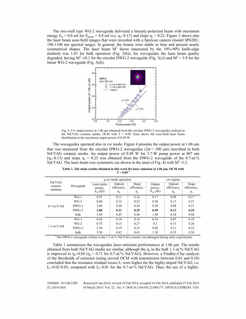
Fig. 4. Cw output power at 1.06 μm obtained from the circular DWG-2 waveguides realized in the Nd:YAG ceramic media, OCM with T = 0.05. Inset shows the near-field laser beam distribution at the maximum output power of 0.49 W.
The waveguides operated also in cw mode. Figure 4 presents the output power at 1.06 μm that was measured from the circular DWG-2 waveguides (2φ = 100 μm) inscribed in both Nd:YAG ceramic media. An output power of 0.49 W for 3.7-W pump power at 807 nm (ηo~0.13) and slope ηs = 0.25 was obtained from the DWG-2 waveguide of the 0.7-at.% Nd:YAG. The laser beam was symmetric (as shown in the inset of Fig. 4) with M2~3.2.
Table 1. The main results obtained in this work for laser emission at 1.06 μm, OCM with T = 0.05*)
Nd:YAG ceramic medium
Waveguide
q-cw mode operation cw regime
Laser pulse energy, Ep (mJ)
Optical efficiency,
ηo
Slope efficiency,
ηs
Output power, Pout (W)
Optical efficiency,
ηo
Slope efficiency,
ηs
0.7-at.% Nd
WG-1 WG-2
DWG-1 DWG-2
bulk
0.550.80 2.60 2.80 5.90
0.110.16 0.20 0.21 0.45
0.160.22 0.24 0.25 0.46
0.170.30 0.30 0.49 1.40
0.08 0.13 0.08 0.13 0.38
0.17 0.21 0.21 0.25 0.44
1.1-at.% Nd
WG-1 WG-2
DWG-2 bulk
0.500.75 2.50 5.50
0.100.15 0.19 0.42
0.180.27 0.23 0.43
0.160.3 0.40 1.30
0.07 0.13 0.11 0.35
0.18 0.26 0.22 0.38
*) The DWG-1 waveguide written in the 1.1-at.% Nd:YAG ceramic was damaged during early experiments.
Table 1 summarizes the waveguides laser emission performances at 1.06 μm. The results obtained from both Nd:YAG media are similar, although the ηa in the bulk 1.1-at.% Nd:YAG is improved to ηa~0.84 (ηa = 0.71 for 0.7-at.% Nd:YAG). However, a Findlay-Clay analysis of the thresholds of emission (using several OCM with transmission between 0.01 and 0.10) concluded that the resonator residual losses Li were higher for the highly-doped Nd:YAG, i.e. Li~0.02-0.03, compared with Li~0.01 for the 0.7-at.% Nd:YAG. Thus, the use of a highly-
#204060 - $15.00 USD Received 6 Jan 2014; revised 10 Feb 2014; accepted 16 Feb 2014; published 27 Feb 2014(C) 2014 OSA 10 March 2014 | Vol. 22, No. 5 | DOI:10.1364/OE.22.005177 | OPTICS EXPRESS 5181
doped 1.1-at.% Nd:YAG improves ηa but increases losses Li, which explains the very close results obtained in both Nd:YAG ceramics for emission at 1.06 μm.
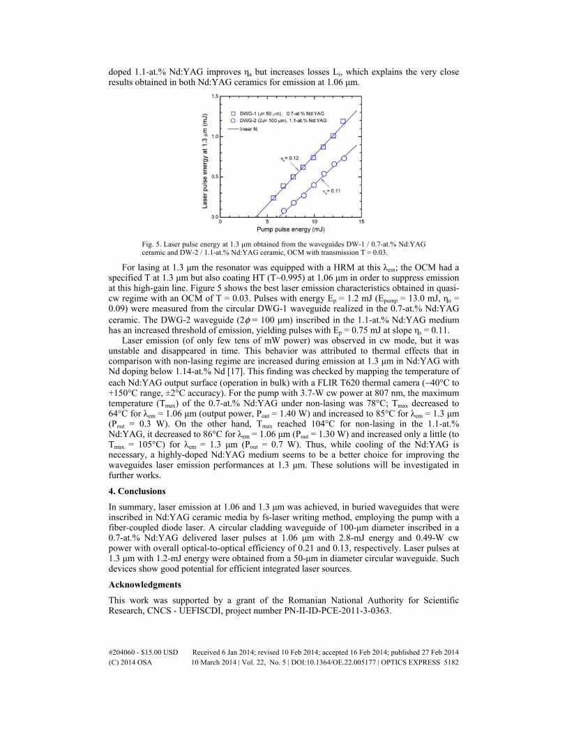
Fig. 5. Laser pulse energy at 1.3 μm obtained from the waveguides DW-1 / 0.7-at.% Nd:YAG ceramic and DW-2 / 1.1-at.% Nd:YAG ceramic, OCM with transmission T = 0.03.
For lasing at 1.3 μm the resonator was equipped with a HRM at this λem; the OCM had a specified T at 1.3 μm but also coating HT (T~0.995) at 1.06 μm in order to suppress emission at this high-gain line. Figure 5 shows the best laser emission characteristics obtained in quasi-cw regime with an OCM of T = 0.03. Pulses with energy Ep = 1.2 mJ (Epump = 13.0 mJ, ηo = 0.09) were measured from the circular DWG-1 waveguide realized in the 0.7-at.% Nd:YAG ceramic. The DWG-2 waveguide (2φ = 100 μm) inscribed in the 1.1-at.% Nd:YAG medium has an increased threshold of emission, yielding pulses with Ep = 0.75 mJ at slope ηs = 0.11.
Laser emission (of only few tens of mW power) was observed in cw mode, but it was unstable and disappeared in time. This behavior was attributed to thermal effects that in comparison with non-lasing regime are increased during emission at 1.3 μm in Nd:YAG with Nd doping below 1.14-at.% Nd [17]. This finding was checked by mapping the temperature of each Nd:YAG output surface (operation in bulk) with a FLIR T620 thermal camera (−40°C to +150°C range, ±2°C accuracy). For the pump with 3.7-W cw power at 807 nm, the maximum temperature (Tmax) of the 0.7-at.% Nd:YAG under non-lasing was 78°C; Tmax decreased to 64°C for λem = 1.06 μm (output power, Pout = 1.40 W) and increased to 85°C for λem = 1.3 μm (Pout = 0.3 W). On the other hand, Tmax reached 104°C for non-lasing in the 1.1-at.% Nd:YAG, it decreased to 86°C for λem = 1.06 μm (Pout = 1.30 W) and increased only a little (to Tmax = 105°C) for λem = 1.3 μm (Pout = 0.7 W). Thus, while cooling of the Nd:YAG is necessary, a highly-doped Nd:YAG medium seems to be a better choice for improving the waveguides laser emission performances at 1.3 μm. These solutions will be investigated in further works.
4. Conclusions
In summary, laser emission at 1.06 and 1.3 μm was achieved, in buried waveguides that were inscribed in Nd:YAG ceramic media by fs-laser writing method, employing the pump with a fiber-coupled diode laser. A circular cladding waveguide of 100-μm diameter inscribed in a 0.7-at.% Nd:YAG delivered laser pulses at 1.06 μm with 2.8-mJ energy and 0.49-W cw power with overall optical-to-optical efficiency of 0.21 and 0.13, respectively. Laser pulses at 1.3 μm with 1.2-mJ energy were obtained from a 50-μm in diameter circular waveguide. Such devices show good potential for efficient integrated laser sources.
Acknowledgments
This work was supported by a grant of the Romanian National Authority for Scientific Research, CNCS - UEFISCDI, project number PN-II-ID-PCE-2011-3-0363.
#204060 - $15.00 USD Received 6 Jan 2014; revised 10 Feb 2014; accepted 16 Feb 2014; published 27 Feb 2014(C) 2014 OSA 10 March 2014 | Vol. 22, No. 5 | DOI:10.1364/OE.22.005177 | OPTICS EXPRESS 5182
Cladding waveguides realized in Nd:YAG ceramic by direct femtosecond-laser writing with
a helical movement technique Gabriela Salamu,1,3,4 Florin Jipa,2,3 Marian Zamfirescu,2 and Nicolaie Pavel1,*
1Laboratory of Solid-State Quantum Electronics, National Institute for Laser, Plasma and Radiation Physics, Bucharest R-077125, Romania
2Solid-State Laser Laboratory, Laser Department, National Institute for Laser, Plasma and Radiation Physics, Bucharest R-077125, Romania
3Doctoral School of Physics, University of Bucharest, Romania [email protected]
Abstract: Circular cladding waveguides were realized in a 5.0-mm long, 1.1-at.% Nd:YAG ceramic by direct femtosecond-laser writing using a scheme in which the laser medium is moved on a helical trajectory along its axis and parallel to the writing direction. Laser emission was obtained under the pump with a fiber-coupled diode laser. A 100-μm diameter waveguide delivered laser pulses at 1.06 μm with 3.4-mJ energy for the pump with pulses of 13.1-mJ energy, at 0.30 slope efficiency; laser pulses at 1.3 μm with 1.2-mJ energy were obtained from the same device. Comparison with a waveguide of the same dimension that was inscribed by the classical translation method of the laser medium is made. Efficient integrated lasers based on cladding waveguides that are pumped by fiber-coupled diode lasers could be realized by this writing method.
©2014 Optical Society of America
OCIS codes: (140.3580) Lasers, solid-state; (140.3530) Lasers, neodymium; (230.7380) Waveguides, channeled; (130.3990) Micro-optical devices.
References and links
1. K. M. Davis, K. Miura, N. Sugimoto, and K. Hirao, “Writing waveguides in glass with a femtosecond laser,” Opt. Lett. 21(21), 1729–1731 (1996).
2. S. Nolte, M. Will, J. Burghoff, and A. Tuennermann, “Femtosecond waveguide writing: a new avenue to three-dimensional integrated optics,” Appl. Phys. A, Mater. Sci. Process. 77(1), 109–111 (2003).
3. C. Grivas, “Optically pumped planar waveguide lasers, Part I: Fundamentals and fabrication techniques,” Prog. Quantum Electron. 35(6), 159–239 (2011).
4. A. Ródenas, G. A. Torchia, G. Lifante, E. Cantelar, J. Lamela, F. Jaque, L. Roso, and D. Jaque, “Refractive index change mechanisms in femtosecond laser written ceramic Nd:YAG waveguides: micro-spectroscopy experiments and beam propagation calculations,” Appl. Phys. B 95(1), 85–96 (2009).
5. G. A. Torchia, A. Rodenas, A. Benayas, E. Cantelar, L. Roso, and D. Jaque, “Highly efficient laser action in femtosecond-written Nd:yttrium aluminum garnet ceramic waveguides,” Appl. Phys. Lett. 92(11), 111103 (2008).
6. T. Calmano, J. Siebenmorgen, O. Hellmig, K. Petermann, and G. Huber, “Nd:YAG waveguide laser with 1.3 W output power, fabricated by direct femtosecond laser writing,” Appl. Phys. B 100(1), 131–135 (2010).
7. F. M. Bain, A. A. Lagatsky, R. R. Thomson, N. D. Psaila, N. V. Kuleshov, A. K. Kar, W. Sibbett, and C. T. A. Brown, “Ultrafast laser inscribed Yb:KGd(WO4)2 and Yb:KY(WO4)2 channel waveguide lasers,” Opt. Express 17(25), 22417–22422 (2009).
8. J. Siebenmorgen, T. Calmano, K. Petermann, and G. Huber, “Highly efficient Yb:YAG channel waveguide laser written with a femtosecond-laser,” Opt. Express 18(15), 16035–16041 (2010).
9. T. Calmano, J. Siebenmorgen, A.-G. Paschke, C. Fiebig, K. Paschke, G. Erbert, K. Petermann, and G. Huber, “Diode pumped high power operation of a femtosecond laser inscribed Yb:YAG waveguide laser,” Opt. Mater. Express 1(3), 428–433 (2011).
10. T. Calmano, A.-G. Paschke, S. Müller, C. Kränkel, and G. Huber, “Curved Yb:YAG waveguide lasers, fabricated by femtosecond laser inscription,” Opt. Express 21(21), 25501–25508 (2013).
11. Y. Tan, F. Chen, J. R. Vázquez de Aldana, G. A. Torchia, A. Benayas, and D. Jaque, “Continuous wave laser generation at 1064 nm in femtosecond laser inscribed Nd:YVO4 channel waveguides,” Appl. Phys. Lett. 97(3), 031119 (2010).
#205723 - $15.00 USD Received 31 Jan 2014; revised 12 Mar 2014; accepted 14 Mar 2014; published 24 Mar 2014(C) 2014 OSA 1 April 2014 | Vol. 4, No. 4 | DOI:10.1364/OME.4.000790 | OPTICAL MATERIALS EXPRESS 790

12. Y. Tan, A. Rodenas, F. Chen, R. R. Thomson, A. K. Kar, D. Jaque, and Q. M. Lu, “70% slope efficiency from an ultrafast laser-written Nd:GdVO4 channel waveguide laser,” Opt. Express 18(24), 24994–24999 (2010).
13. T. Calmano, J. Siebenmorgen, F. Reichert, M. Fechner, A.-G. Paschke, N.-O. Hansen, K. Petermann, and G. Huber, “Crystalline Pr:SrAl12O19 waveguide laser in the visible spectral region,” Opt. Lett. 36(23), 4620–4622 (2011).
14. A. G. Okhrimchuk, A. V. Shestakov, I. Khrushchev, and J. Mitchell, “Depressed cladding, buried waveguide laser formed in a YAG:Nd3+ crystal by femtosecond laser writing,” Opt. Lett. 30(17), 2248–2250 (2005).
15. A. Okhrimchuk, V. Mezentsev, A. Shestakov, and I. Bennion, “Low loss depressed cladding waveguide inscribed in YAG:Nd single crystal by femtosecond laser pulses,” Opt. Express 20(4), 3832–3843 (2012).
16. H. Liu, Y. Jia, J. R. Vázquez de Aldana, D. Jaque, and F. Chen, “Femtosecond laser inscribed cladding waveguides in Nd:YAG ceramics: Fabrication, fluorescence imaging and laser performance,” Opt. Express 20(17), 18620–18629 (2012).
17. Y. Ren, G. Brown, A. Ródenas, S. Beecher, F. Chen, and A. K. Kar, “Mid-infrared waveguide lasers in rare-earth-doped YAG,” Opt. Lett. 37(16), 3339–3341 (2012).
18. Q. An, Y. Ren, Y. Jia, J. R. V. de Aldana, and F. Chen, “Mid-infrared waveguides in zinc sulfide crystal,” Opt. Mater. Express 3(4), 466–471 (2013).
19. S. Müller, T. Calmano, P. Metz, N.-O. Hansen, C. Kränkel, and G. Huber, “Femtosecond-laser-written diode-pumped Pr:LiYF4 waveguide laser,” Opt. Lett. 37(24), 5223–5225 (2012).
20. H. Liu, F. Chen, J. R. Vázquez de Aldana, and D. Jaque, “Femtosecond-laser inscribed double-cladding waveguides in Nd:YAG crystal: a promising prototype for integrated lasers,” Opt. Lett. 38(17), 3294–3297 (2013).
21. N. Pavel, G. Salamu, F. Voicu, F. Jipa, M. Zamfirescu, and T. Dascalu, “Efficient laser emission in diode-pumped Nd:YAG buried waveguides realized by direct femtosecond-laser writing,” Laser Phys. Lett. 10(9), 095802 (2013).
22. G. Salamu, F. Voicu, N. Pavel, T. Dascalu, F. Jipa, and M. Zamfirescu, “Laser emission in diode-pumped Nd:YAG single-crystal waveguides realized by direct femtosecond-laser writing technique,” Rom. Reports in Physics 65(3), 943–953 (2013).
23. G. Salamu, F. Jipa, M. Zamfirescu, and N. Pavel, “Laser emission from diode-pumped Nd:YAG ceramic waveguide lasers realized by direct femtosecond-laser writing technique,” Opt. Express 22(5), 5177–5182 (2014).
24. O. Caulier, D. Le Coq, E. Bychkov, and P. Masselin, “Direct laser writing of buried waveguide in As2S3 glass using a helical sample translation,” Opt. Lett. 38(20), 4212–4215 (2013).
25. N. Pavel, V. Lupei, J. Saikawa, T. Taira, and H. Kan, “Neodymium concentration dependence of 0.94, 1.06 and 1.34 μm laser emission and of heating effects under 809 and 885-nm diode laser pumping of Nd:YAG,” Appl. Phys. B 82(4), 599–605 (2006).
1. Introduction
Since the first realization of waveguides in glasses by direct writing with femtosecond (fs)-laser pulses [1], micro-structuring have been performed in various materials. It was shown that two- or three-dimensional optical devices can be shaped using this inscribing technique [2], aiming a large range of applications. Among these devices the waveguide lasers [3] show interesting features, like compactness, low emission threshold and output performances close of those yielded by the bulk material, which makes them very attractive in optoelectronics. The writing process depends mainly of the material type and of the fs-laser pulse characteristics. In many glasses the irradiated material melts during the writing process and then it re-solidifies. A track with a higher refractive index compared with that of the bulk medium results, this track being used itself for light propagation.
On the other hand, in the case of a lot of laser crystals the writing process alters the medium inside the track (where a lower refractive index is obtained in comparison with that of the bulk) and causes a stress-induced refractive index increase in the adjacent regions. The light is guided in between two such tracks (or walls) [4]. Buried waveguides of two-wall type have been inscribed in various laser active media, such as Nd:Y3Al5O12 (Nd:YAG) [5,6], Yb-doped monoclinic potassium double tungstates [7], Yb:YAG [8–10], Nd:YVO4 [11] and Nd:GdVO4 [12], or Pr:SrAl12O19 [13]. Efficient laser emission was reported from these waveguides pumped with tunable Ti:sapphire lasers [5,6,8,10–13] or with diode lasers [7,9].
A step forward toward realization of a compact waveguide laser was the demonstration of the depressed-cladding waveguide [14]. Using this technique structures with tubular shapes can be fabricated by writing many parallel tracks around a defined contour. Thus, waveguides having rectangular and elliptical cross-sections were realized in Nd:YAG single crystals [14,15], with circular, hexagonal and trapezoidal shapes in Nd:YAG ceramic [16], circular in Tm:YAG ceramic [17] or ZnS [18], rhombic in Pr:YLiF4 [19], or of circular double-cladding
#205723 - $15.00 USD Received 31 Jan 2014; revised 12 Mar 2014; accepted 14 Mar 2014; published 24 Mar 2014(C) 2014 OSA 1 April 2014 | Vol. 4, No. 4 | DOI:10.1364/OME.4.000790 | OPTICAL MATERIALS EXPRESS 791
shapes in Nd:YAG [20]. Because the waveguide dimensions can be increased the pump with diode laser becomes feasible [15,19]. Using the pump with a fiber-coupled diode laser we have reported recently laser emission at 1.06 μm and 1.3 μm from two-wall type and cladding (circular and rectangular shaped) waveguides that were inscribed in Nd:YAG single crystal [21,22] or from circular waveguides that were written in Nd:YAG ceramic media [23]; laser emission on the quasi-three-level 4F3/2→4I9/2 transition at 946 nm was also observed [22].
The cladding waveguides mentioned above were obtained with a technique similar to that proposed in [14]. In this arrangement the fs-laser beam employed for writing and the laser crystal direction used for lasing were perpendicular to each other. The laser crystal was translated and once the writing was made along the entire medium length the fs-laser focusing position was moved to a new location. Many tracks are inscribed around the waveguide shape, but there is always a space of unmodified refractive index left between any consecutive tracks.
In this work we are using a scheme in which the laser crystal is moved along a helical trajectory during the writing process [24], eliminating the regions with unchanged refractive index. Furthermore, a geometry in which the fs-laser beam is parallel to the crystal axis used for lasing is considered. We have applied this arrangement to inscribe, in Nd:YAG ceramic, circular waveguides with well defined walls. Efficient laser emission at 1.06 μm and 1.3 μm is obtained under the pump with a fiber-coupled laser diode. Thus, a waveguide with 100-μm diameter that was realized in a 5.0-mm long, 1.1-at.% Nd:YAG ceramic yielded laser pulses of 3.4-mJ energy at 1.06 μm and of 1.2-mJ energy at 1.3 μm, with overall optical-to-optical efficiency of 0.26 and 0.09, respectively. To the best of the authors’ knowledge this is the first time when helical movement is applied for writing waveguides in a laser medium.
2. Waveguide fabrication
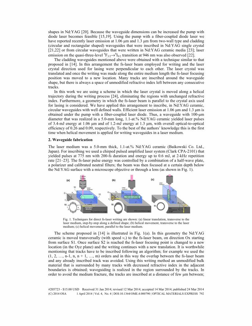
The laser medium was a 5.0-mm thick, 1.1-at.% Nd:YAG ceramic (Baikowski Co. Ltd., Japan). For inscribing we used a chirped pulsed amplified laser system (Clark CPA-2101) that yielded pulses at 775 nm with 200-fs duration and energy up to 0.6 mJ, at 2-kHz repetition rate [21–23]. The fs-laser pulse energy was controlled by a combination of a half-wave plate, a polarizer and calibrated neutral filters; the beam was then focused at a certain depth below the Nd:YAG surface with a microscope objective or through a lens (as shown in Fig. 1).
Fig. 1. Techniques for direct fs-laser writing are shown: (a) linear translation, transverse to the laser medium, step-by-step along a defined shape; (b) helical movement, transverse to the laser medium; (c) helical movement, parallel to the laser medium.
The scheme proposed in [14] is illustrated in Fig. 1(a). In this geometry the Nd:YAG ceramic is moved transversally (with speed v1) to the fs-laser beam, on direction Ox starting from surface S1. Once surface S2 is reached the fs-laser focusing point is changed to a new location (in the Oyz plane) and the writing continues with a new translation. It is worthwhile mentioning that tracks have to be inscribed following an algorithm; for example we used the (1, 2, …, n-1, n, n + 1, …, m) orders and in this way the overlap between the fs-laser beam and any already inscribed track was avoided. Using this writing method an unmodified bulk material that is surrounded by many tracks with decreased refractive index in the adjacent boundaries is obtained; waveguiding is realized in the region surrounded by the tracks. In order to avoid the medium fracture, the tracks are inscribed at a distance of few μm between;
#205723 - $15.00 USD Received 31 Jan 2014; revised 12 Mar 2014; accepted 14 Mar 2014; published 24 Mar 2014(C) 2014 OSA 1 April 2014 | Vol. 4, No. 4 | DOI:10.1364/OME.4.000790 | OPTICAL MATERIALS EXPRESS 792
an unmodified material will therefore remain between the tracks (as illustrated in the inset of Fig. 1(a)). These regions with unchanged refractive index can increase the waveguide propagation losses, decreasing thus the laser emission performances.
A better overlap between the inscribed marks that build the waveguide walls can be achieved by moving the Nd:YAG medium on a helical trajectory. As a first choice, the medium motion can be perpendicular to the fs-laser beam (Fig. 1(b)). The right selection of the rotation velocity (in the Oyz plane) and of the speed translation (v2 on direction Ox) can deliver a smooth aspect of the walls (inset of Fig. 1(b)). Still the wall is not rounding, as the shape of the inscribed marks depends on the characteristics of the focusing optics.
As an alternative solution the Nd:YAG is 90° rotated on the motorized stage and the writing is made parallel to the direction on which laser emission will be obtained, as shown in Fig. 1(c). In this case the medium is moved circularly in the Oxy plane and translation is performed on direction Oz (with speed v3). This writing method can provide waveguides with circular walls (inset of Fig. 1(c)). Moreover, because the typical depth of an inscribed mark has few tens of μm, the translation speed is increased in comparison with the arrangement from Fig. 1(b). We comment that the helical movement can be replaced by a sequence of a circular trajectory in the Oyz plane followed by a step translation on direction Oz. These arrangements require a carefully choice of the focusing optics such as to realize inscribing on a medium with length sufficient for efficient absorption of the pump beam. Additional
adjustments of the fs-laser beam energy may be necessary in the writing process as the focus point moves on a considerable depth below surface S2 of the Nd:YAG medium.
For the lasing experiments we inscribed three circular (with diameters of 50, 80 and 100 μm) cladding waveguides in the Nd:YAG ceramic by using helical movement of the medium. A 10× microscope objective with a numerical aperture (NA) of 0.30 was employed to focus the fs-laser beam to a diameter (in air) of ~12 μm. A video camera was used to visualize the process and thus to choose suitable writing parameters for a good overlap between the traces inscribed at each helix. For example, in the case of the 100-μm diameter structure a complete circle in the Oxy plane was done in 0.84 sec. The fs-laser pulse energy was set at 15 μJ. The depth of the track inscribed in Nd:YAG on Oz direction was measured, and based on this evaluation the pitch of the helical trajectory was fixed at 40 μm. Thus, the time necessary for writing this waveguide was ~105 sec. The Nd:YAG end faces (S1 and S2) were polished after inscribing, and the final length of the laser medium was 4.7 mm.
Fig. 2. Microscope images (in reflection mode) of the circular waveguides inscribed in the Nd:YAG ceramic by helical moving: (a) DWG-1, φ = 100 μm; (b) DWG-3, φ = 50 μm; the (c) DWG-4, φ = 100 μm was obtained by the step-by-step translation technique. Top views of the walls along the translation direction for the (d) DWG-1 and (e) DWG-4 waveguides are shown.
Cross-section views of some circular waveguides are presented in Fig. 2. The waveguides realized by the Nd:YAG helical movement will be denoted by DWG-1 (with diameter φ = 100μm in Fig. 2(a)), by DWG-2 (φ = 80 μm, not shown) and by DWG-3 (with φ = 50 μm in Fig. 2(b)). For comparison a fourth waveguide with φ = 100 μm (indicated in Fig. 2(c) by DWG-4) was obtained by the classical method. In this writing the fs-laser beam, of ~1.5-μJ
#205723 - $15.00 USD Received 31 Jan 2014; revised 12 Mar 2014; accepted 14 Mar 2014; published 24 Mar 2014(C) 2014 OSA 1 April 2014 | Vol. 4, No. 4 | DOI:10.1364/OME.4.000790 | OPTICAL MATERIALS EXPRESS 793
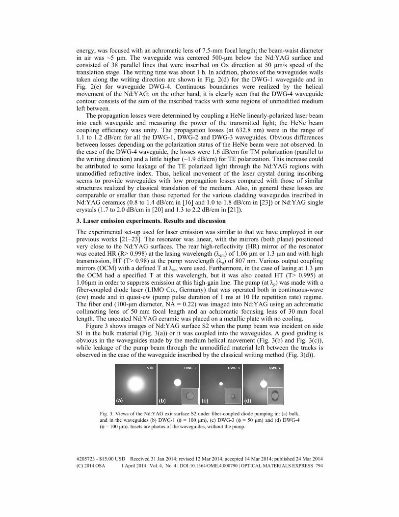
energy, was focused with an achromatic lens of 7.5-mm focal length; the beam-waist diameter in air was ~5 μm. The waveguide was centered 500-μm below the Nd:YAG surface and consisted of 38 parallel lines that were inscribed on Ox direction at 50 μm/s speed of the translation stage. The writing time was about 1 h. In addition, photos of the waveguides walls taken along the writing direction are shown in Fig. 2(d) for the DWG-1 waveguide and in Fig. 2(e) for waveguide DWG-4. Continuous boundaries were realized by the helical movement of the Nd:YAG; on the other hand, it is clearly seen that the DWG-4 waveguide contour consists of the sum of the inscribed tracks with some regions of unmodified medium left between.
The propagation losses were determined by coupling a HeNe linearly-polarized laser beam into each waveguide and measuring the power of the transmitted light; the HeNe beam coupling efficiency was unity. The propagation losses (at 632.8 nm) were in the range of 1.1 to 1.2 dB/cm for all the DWG-1, DWG-2 and DWG-3 waveguides. Obvious differences between losses depending on the polarization status of the HeNe beam were not observed. In the case of the DWG-4 waveguide, the losses were 1.6 dB/cm for TM polarization (parallel to the writing direction) and a little higher (~1.9 dB/cm) for TE polarization. This increase could be attributed to some leakage of the TE polarized light through the Nd:YAG regions with unmodified refractive index. Thus, helical movement of the laser crystal during inscribing seems to provide waveguides with low propagation losses compared with those of similar structures realized by classical translation of the medium. Also, in general these losses are comparable or smaller than those reported for the various cladding waveguides inscribed in Nd:YAG ceramics (0.8 to 1.4 dB/cm in [16] and 1.0 to 1.8 dB/cm in [23]) or Nd:YAG single crystals (1.7 to 2.0 dB/cm in [20] and 1.3 to 2.2 dB/cm in [21]).
3. Laser emission experiments. Results and discussion
The experimental set-up used for laser emission was similar to that we have employed in our previous works [21–23]. The resonator was linear, with the mirrors (both plane) positioned very close to the Nd:YAG surfaces. The rear high-reflectivity (HR) mirror of the resonator was coated HR (R> 0.998) at the lasing wavelength (λem) of 1.06 μm or 1.3 μm and with high transmission, HT (T> 0.98) at the pump wavelength (λp) of 807 nm. Various output coupling mirrors (OCM) with a defined T at λem were used. Furthermore, in the case of lasing at 1.3 μm the OCM had a specified T at this wavelength, but it was also coated HT (T> 0.995) at 1.06μm in order to suppress emission at this high-gain line. The pump (at λp) was made with a fiber-coupled diode laser (LIMO Co., Germany) that was operated both in continuous-wave (cw) mode and in quasi-cw (pump pulse duration of 1 ms at 10 Hz repetition rate) regime. The fiber end (100-μm diameter, NA = 0.22) was imaged into Nd:YAG using an achromatic collimating lens of 50-mm focal length and an achromatic focusing lens of 30-mm focal length. The uncoated Nd:YAG ceramic was placed on a metallic plate with no cooling.
Figure 3 shows images of Nd:YAG surface S2 when the pump beam was incident on side S1 in the bulk material (Fig. 3(a)) or it was coupled into the waveguides. A good guiding is obvious in the waveguides made by the medium helical movement (Fig. 3(b) and Fig. 3(c)), while leakage of the pump beam through the unmodified material left between the tracks is observed in the case of the waveguide inscribed by the classical writing method (Fig. 3(d)).
Fig. 3. Views of the Nd:YAG exit surface S2 under fiber-coupled diode pumping in: (a) bulk, and in the waveguides (b) DWG-1 (φ = 100 μm), (c) DWG-3 (φ = 50 μm) and (d) DWG-4 (φ = 100 μm). Insets are photos of the waveguides, without the pump.
#205723 - $15.00 USD Received 31 Jan 2014; revised 12 Mar 2014; accepted 14 Mar 2014; published 24 Mar 2014(C) 2014 OSA 1 April 2014 | Vol. 4, No. 4 | DOI:10.1364/OME.4.000790 | OPTICAL MATERIALS EXPRESS 794

Characteristics of the laser emission at λem = 1.06 μm that was obtained from the 100-μm diameter DWG-1 waveguide in quasi-cw pumping regime are given in Fig. 4(a). With an OCM of T = 0.01 this waveguide yielded laser pulses with maximum energy Ep = 1.1 mJ for the pump with pulses of energy Epump = 13.1 mJ; the slope efficiency was ηs = 0.09. The best performances were recorded when the OCM had T = 0.10: The energy Ep increased at 3.4 mJ (the overall optical-to-optical efficiency ηo was ~0.26) and the slope efficiency improved to ηs = 0.30. The near-field distribution (recorded with a Spiricon camera, model SP620U, 190-1100 nm spectral range) is shown in Fig. 4(b). The beam was stable in time and its transverse distribution was highly multimode with a M2 factor (measured by the 10%-90% knife-edge method) of ~27. We mention that the Nd:YAG bulk delivered laser pulses with Ep = 5.5 mJ (ηo = 0.42) at slope ηs = 0.45. The beam transverse mode (its near-field distribution is shown in Fig. 4(c)) has M2~5.0. The pump-beam absorption efficiency in bulk was measured to be ηa~0.80. A comparison between laser performances obtained in bulk and in the waveguide should be made carefully, because the fraction of the pump power that is coupled and then absorbed into the waveguide, or the waveguide losses cannot be determined exactly. Nevertheless, by using an integral overlap between the pump beam shape and the waveguide input surface the pump beam coupling efficiency (ηc) was calculated close to unity. Thus, the lower performances of waveguide were due mainly to its larger propagation losses compared with those of the bulk Nd:YAG; these losses influence the fraction of the pump light absorbed in the waveguide, as well as the laser emission performances.
Fig. 4. (a) Laser pulse energy at 1.06 μm versus energy of the pump pulse incident on the DWG-1 waveguide. The near-field distributions are shown at the maximum laser pulse energy (OCM with T = 0.10) for emission in (b) DWG-1 (Ep = 3.4 mJ) and (c) bulk Nd:YAG (Ep = 5.5 mJ).
Fig. 5. The best performances obtained from the waveguides in quasi-cw operation for emission at: (a) λem = 1.06 μm, OCM with T = 0.10; (b) λem = 1.3 μm, OCM with T = 0.03.
#205723 - $15.00 USD Received 31 Jan 2014; revised 12 Mar 2014; accepted 14 Mar 2014; published 24 Mar 2014(C) 2014 OSA 1 April 2014 | Vol. 4, No. 4 | DOI:10.1364/OME.4.000790 | OPTICAL MATERIALS EXPRESS 795
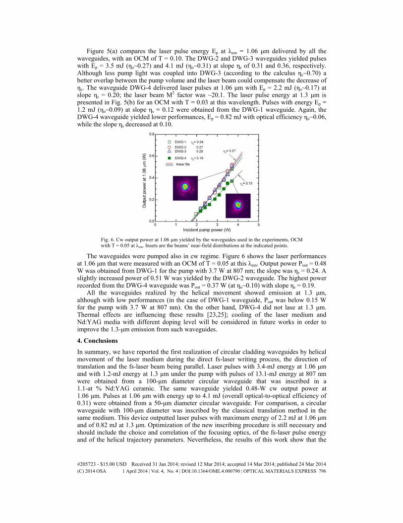
Figure 5(a) compares the laser pulse energy Ep at λem = 1.06 μm delivered by all the waveguides, with an OCM of T = 0.10. The DWG-2 and DWG-3 waveguides yielded pulses with Ep = 3.5 mJ (ηo~0.27) and 4.1 mJ (ηo~0.31) at slope ηs of 0.31 and 0.36, respectively. Although less pump light was coupled into DWG-3 (according to the calculus ηc~0.70) a better overlap between the pump volume and the laser beam could compensate the decrease of ηc. The waveguide DWG-4 delivered laser pulses at 1.06 μm with Ep = 2.2 mJ (ηo~0.17) at slope ηs = 0.20; the laser beam M2 factor was ~20.1. The laser pulse energy at 1.3 μm is presented in Fig. 5(b) for an OCM with T = 0.03 at this wavelength. Pulses with energy Ep = 1.2 mJ (ηo~0.09) at slope ηs = 0.12 were obtained from the DWG-1 waveguide. Again, the DWG-4 waveguide yielded lower performances, Ep = 0.82 mJ with optical efficiency ηo~0.06, while the slope ηs decreased at 0.10.
Fig. 6. Cw output power at 1.06 μm yielded by the waveguides used in the experiments, OCM with T = 0.05 at λem. Insets are the beams’ near-field distributions at the indicated points.
The waveguides were pumped also in cw regime. Figure 6 shows the laser performances at 1.06 μm that were measured with an OCM of T = 0.05 at this λem. Output power Pout = 0.48 W was obtained from DWG-1 for the pump with 3.7 W at 807 nm; the slope was ηs = 0.24. A slightly increased power of 0.51 W was yielded by the DWG-2 waveguide. The highest power recorded from the DWG-4 waveguide was Pout = 0.37 W (at ηo~0.10) with slope ηs = 0.19.
All the waveguides realized by the helical movement showed emission at 1.3 μm, although with low performances (in the case of DWG-1 waveguide, Pout was below 0.15 W for the pump with 3.7 W at 807 nm). On the other hand, DWG-4 did not lase at 1.3 μm. Thermal effects are influencing these results [23,25]; cooling of the laser medium and Nd:YAG media with different doping level will be considered in future works in order to improve the 1.3-μm emission from such waveguides.
4. Conclusions
In summary, we have reported the first realization of circular cladding waveguides by helical movement of the laser medium during the direct fs-laser writing process, the direction of translation and the fs-laser beam being parallel. Laser pulses with 3.4-mJ energy at 1.06 μm and with 1.2-mJ energy at 1.3 μm under the pump with pulses of 13.1-mJ energy at 807 nm were obtained from a 100-μm diameter circular waveguide that was inscribed in a 1.1-at % Nd:YAG ceramic. The same waveguide yielded 0.48-W cw output power at 1.06 μm. Pulses at 1.06 μm with energy up to 4.1 mJ (overall optical-to-optical efficiency of 0.31) were obtained from a 50-μm diameter circular waveguide. For comparison, a circular waveguide with 100-μm diameter was inscribed by the classical translation method in the same medium. This device outputted laser pulses with maximum energy of 2.2 mJ at 1.06 μm and of 0.82 mJ at 1.3 μm. Optimization of the new inscribing procedure is still necessary and should include the choice and correlation of the focusing optics, of the fs-laser pulse energy and of the helical trajectory parameters. Nevertheless, the results of this work show that the
#205723 - $15.00 USD Received 31 Jan 2014; revised 12 Mar 2014; accepted 14 Mar 2014; published 24 Mar 2014(C) 2014 OSA 1 April 2014 | Vol. 4, No. 4 | DOI:10.1364/OME.4.000790 | OPTICAL MATERIALS EXPRESS 796

helical movement of the laser medium during fs-laser writing could be a step forward towards realization of efficient integrated lasers consisting of cladding waveguides pumped by diode lasers.
Acknowledgments
This work was financed by a grant of the Romanian National Authority for Scientific Research, CNCS - UEFISCDI, project number PN-II-ID-PCE-2011-3-0363 and partially supported by the EC initiative LASERLAB-EUROPE (contract no. 284464) - WP33 - European Research Objectives on Lasers for Industry, Technology and Energy (EURO-LITE).
#205723 - $15.00 USD Received 31 Jan 2014; revised 12 Mar 2014; accepted 14 Mar 2014; published 24 Mar 2014(C) 2014 OSA 1 April 2014 | Vol. 4, No. 4 | DOI:10.1364/OME.4.000790 | OPTICAL MATERIALS EXPRESS 797

THE PUBLISHING HOUSE PROCEEDINGS OF THE ROMANIAN ACADEMY, Series A, OF THE ROMANIAN ACADEMY Volume 15, Number 2/2014, pp. 151–158
CLADDING WAVEGUIDES REALIZED IN Nd:YAG LASER MEDIA BY DIRECT WRITING WITH A FEMTOSECOND-LASER BEAM
Nicolaie PAVEL1, Gabriela SALAMU1,3, Flavius VOICU1,3, Florin JIPA2,3, Marian ZAMFIRESCU2
1 Laboratory of Solid-State Quantum Electronics, National Institute for Laser, Plasma and Radiation Physics, Bucharest R-077125, Romania
2 Solid-State Laser Laboratory, Laser Department, National Institute for Laser, Plasma and Radiation Physics, Bucharest R-077125, Romania
3 University of Bucharest, Doctoral School of Physics, Romania Corresponding author: Nicolaie PAVEL, E-mail: [email protected]
We report on realization of buried cladding waveguides in Nd:YAG single crystal and ceramic media by direct femtosecond (fs)-laser writing technique. A classical technique that moves the laser medium transversally to the fs-laser beam, as well as a new scheme in which the laser medium has a motion on a helical trajectory during the inscribing process was used. The waveguides laser emission performances at 1.06 and 1.3 µm have been investigated under the pump at 807 nm with a fiber-coupled diode laser that was operated both in quasi-continuous wave (quasi-cw) and in cw regimes. Laser pulses with energy of 3.45 mJ at 1.06 µm and of 1.05 mJ at 1.3 µm (with overall optical-to-optical efficiency of 0.26 and 0.08, respectively) were obtained from a 50 µm in diameter circular waveguide that was inscribed by the helical-moving techniques in a 5.0-mm long, 1.1-at.% Nd:YAG ceramic medium. Characteristics of the laser emission recorded in cw operation are discussed.
Key words: lasers, solid-state lasers, diode-pumped lasers, neodymium, optical waveguides.
1. INTRODUCTION
Due to their unique features like small dimensions, low threshold of operation and good output performances, the waveguides lasers present high interest in optoelectronics. Various methods can be used to obtain such a laser device [1]. Extensive research has been carried out recently on realizing waveguides by writing directly with a fs-laser beam. Within this approach a focalized fs-laser pulse produces modifications at micro or sub-micrometric scale inside the material, thus inducing changes of the refractive index. For the first time such a method was used to inscribe waveguides in glasses [2]. It is worth to emphasize that in this kind of material the irradiated volume melts during the process and then it re-solidifies. Finally, the inscribing process delivers a track with an increased index of refraction compared with that of the bulk (the free or the unmodified) glass, and the track is used itself for light propagation.
The direct fs-laser writing technique is nowadays recognized as a powerful tool for obtaining waveguides with various geometries in many laser media [3]. In this case, the irradiated region of the material can be even damaged during the writing process and an increase of the refraction index in the adjacent zones results by stress. Consequently, the light propagates in the medium that remains unmodified between two such tracks [4]. Laser emission was reported from two-wall type waveguides that were inscribed in well-known active media, like Nd:Y3Al5O12 (Nd:YAG) [5], Yb:YAG [6, 7], or Nd-vanadates [8, 9]. In the experiments, the pump was made with tunable Ti:sapphire lasers. Thus, while the efficiency of such a waveguide laser is high, the output power is limited and the device compactness is restricted by the pump source dimensions.
A compact waveguide laser should include also the pump source, which usually is an array or a fiber-coupled diode laser. A step forward to realization of such a laser device was the proposal of a new inscribing procedure in which many tracks are written around a defined contour [10, 11]. This process delivers a structure that is called “depressed-cladding waveguide”: A principal feature of the inscribed tracks is that it
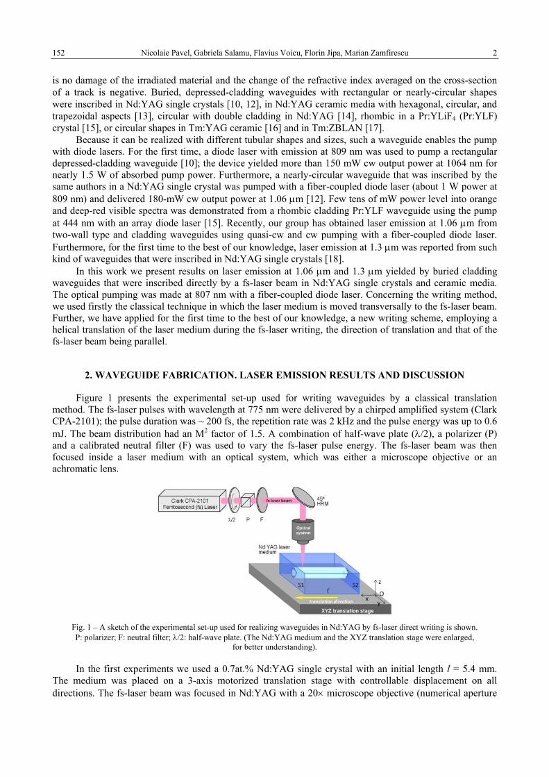
Nicolaie Pavel, Gabriela Salamu, Flavius Voicu, Florin Jipa, Marian Zamfirescu 2 152
is no damage of the irradiated material and the change of the refractive index averaged on the cross-section of a track is negative. Buried, depressed-cladding waveguides with rectangular or nearly-circular shapes were inscribed in Nd:YAG single crystals [10, 12], in Nd:YAG ceramic media with hexagonal, circular, and trapezoidal aspects [13], circular with double cladding in Nd:YAG [14], rhombic in a Pr:YLiF4 (Pr:YLF) crystal [15], or circular shapes in Tm:YAG ceramic [16] and in Tm:ZBLAN [17].
Because it can be realized with different tubular shapes and sizes, such a waveguide enables the pump with diode lasers. For the first time, a diode laser with emission at 809 nm was used to pump a rectangular depressed-cladding waveguide [10]; the device yielded more than 150 mW cw output power at 1064 nm for nearly 1.5 W of absorbed pump power. Furthermore, a nearly-circular waveguide that was inscribed by the same authors in a Nd:YAG single crystal was pumped with a fiber-coupled diode laser (about 1 W power at 809 nm) and delivered 180-mW cw output power at 1.06 µm [12]. Few tens of mW power level into orange and deep-red visible spectra was demonstrated from a rhombic cladding Pr:YLF waveguide using the pump at 444 nm with an array diode laser [15]. Recently, our group has obtained laser emission at 1.06 µm from two-wall type and cladding waveguides using quasi-cw and cw pumping with a fiber-coupled diode laser. Furthermore, for the first time to the best of our knowledge, laser emission at 1.3 µm was reported from such kind of waveguides that were inscribed in Nd:YAG single crystals [18].
In this work we present results on laser emission at 1.06 µm and 1.3 µm yielded by buried cladding waveguides that were inscribed directly by a fs-laser beam in Nd:YAG single crystals and ceramic media. The optical pumping was made at 807 nm with a fiber-coupled diode laser. Concerning the writing method, we used firstly the classical technique in which the laser medium is moved transversally to the fs-laser beam. Further, we have applied for the first time to the best of our knowledge, a new writing scheme, employing a helical translation of the laser medium during the fs-laser writing, the direction of translation and that of the fs-laser beam being parallel.
2. WAVEGUIDE FABRICATION. LASER EMISSION RESULTS AND DISCUSSION
Figure 1 presents the experimental set-up used for writing waveguides by a classical translation method. The fs-laser pulses with wavelength at 775 nm were delivered by a chirped amplified system (Clark CPA-2101); the pulse duration was ~ 200 fs, the repetition rate was 2 kHz and the pulse energy was up to 0.6 mJ. The beam distribution had an M2 factor of 1.5. A combination of half-wave plate (λ/2), a polarizer (P) and a calibrated neutral filter (F) was used to vary the fs-laser pulse energy. The fs-laser beam was then focused inside a laser medium with an optical system, which was either a microscope objective or an achromatic lens.
Fig. 1 – A sketch of the experimental set-up used for realizing waveguides in Nd:YAG by fs-laser direct writing is shown. P: polarizer; F: neutral filter; λ/2: half-wave plate. (The Nd:YAG medium and the XYZ translation stage were enlarged,
for better understanding).
In the first experiments we used a 0.7at.% Nd:YAG single crystal with an initial length l = 5.4 mm. The medium was placed on a 3-axis motorized translation stage with controllable displacement on all directions. The fs-laser beam was focused in Nd:YAG with a 20× microscope objective (numerical aperture
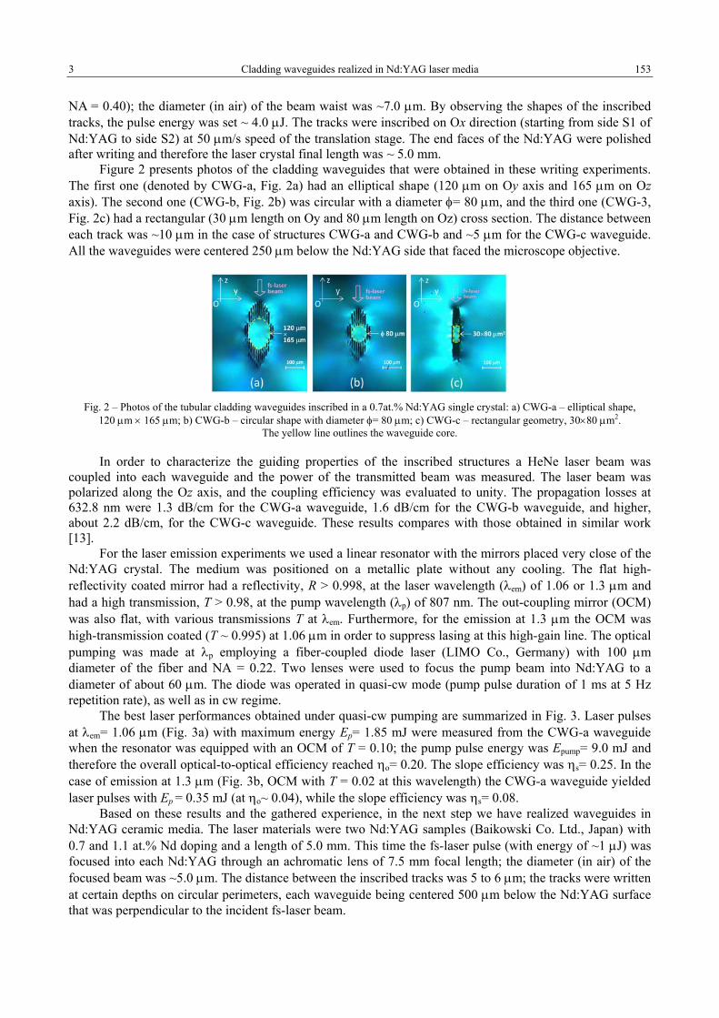
3 Cladding waveguides realized in Nd:YAG laser media 153
NA = 0.40); the diameter (in air) of the beam waist was ~7.0 µm. By observing the shapes of the inscribed tracks, the pulse energy was set ~ 4.0 µJ. The tracks were inscribed on Ox direction (starting from side S1 of Nd:YAG to side S2) at 50 µm/s speed of the translation stage. The end faces of the Nd:YAG were polished after writing and therefore the laser crystal final length was ~ 5.0 mm.
Figure 2 presents photos of the cladding waveguides that were obtained in these writing experiments. The first one (denoted by CWG-a, Fig. 2a) had an elliptical shape (120 µm on Oy axis and 165 µm on Oz axis). The second one (CWG-b, Fig. 2b) was circular with a diameter φ= 80 µm, and the third one (CWG-3, Fig. 2c) had a rectangular (30 µm length on Oy and 80 µm length on Oz) cross section. The distance between each track was ~10 µm in the case of structures CWG-a and CWG-b and ~5 µm for the CWG-c waveguide. All the waveguides were centered 250 µm below the Nd:YAG side that faced the microscope objective.
Fig. 2 – Photos of the tubular cladding waveguides inscribed in a 0.7at.% Nd:YAG single crystal: a) CWG-a – elliptical shape,
120 µm × 165 µm; b) CWG-b – circular shape with diameter φ= 80 µm; c) CWG-c – rectangular geometry, 30×80 µm2. The yellow line outlines the waveguide core.
In order to characterize the guiding properties of the inscribed structures a HeNe laser beam was coupled into each waveguide and the power of the transmitted beam was measured. The laser beam was polarized along the Oz axis, and the coupling efficiency was evaluated to unity. The propagation losses at 632.8 nm were 1.3 dB/cm for the CWG-a waveguide, 1.6 dB/cm for the CWG-b waveguide, and higher, about 2.2 dB/cm, for the CWG-c waveguide. These results compares with those obtained in similar work [13].
For the laser emission experiments we used a linear resonator with the mirrors placed very close of the Nd:YAG crystal. The medium was positioned on a metallic plate without any cooling. The flat high-reflectivity coated mirror had a reflectivity, R > 0.998, at the laser wavelength (λem) of 1.06 or 1.3 µm and had a high transmission, T > 0.98, at the pump wavelength (λp) of 807 nm. The out-coupling mirror (OCM) was also flat, with various transmissions T at λem. Furthermore, for the emission at 1.3 µm the OCM was high-transmission coated (T ~ 0.995) at 1.06 µm in order to suppress lasing at this high-gain line. The optical pumping was made at λp employing a fiber-coupled diode laser (LIMO Co., Germany) with 100 µm diameter of the fiber and NA = 0.22. Two lenses were used to focus the pump beam into Nd:YAG to a diameter of about 60 µm. The diode was operated in quasi-cw mode (pump pulse duration of 1 ms at 5 Hz repetition rate), as well as in cw regime.
The best laser performances obtained under quasi-cw pumping are summarized in Fig. 3. Laser pulses at λem= 1.06 µm (Fig. 3a) with maximum energy Ep= 1.85 mJ were measured from the CWG-a waveguide when the resonator was equipped with an OCM of T = 0.10; the pump pulse energy was Epump= 9.0 mJ and therefore the overall optical-to-optical efficiency reached ηo= 0.20. The slope efficiency was ηs= 0.25. In the case of emission at 1.3 µm (Fig. 3b, OCM with T = 0.02 at this wavelength) the CWG-a waveguide yielded laser pulses with Ep = 0.35 mJ (at ηo~ 0.04), while the slope efficiency was ηs= 0.08.
Based on these results and the gathered experience, in the next step we have realized waveguides in Nd:YAG ceramic media. The laser materials were two Nd:YAG samples (Baikowski Co. Ltd., Japan) with 0.7 and 1.1 at.% Nd doping and a length of 5.0 mm. This time the fs-laser pulse (with energy of ~1 µJ) was focused into each Nd:YAG through an achromatic lens of 7.5 mm focal length; the diameter (in air) of the focused beam was ~5.0 µm. The distance between the inscribed tracks was 5 to 6 µm; the tracks were written at certain depths on circular perimeters, each waveguide being centered 500 µm below the Nd:YAG surface that was perpendicular to the incident fs-laser beam.
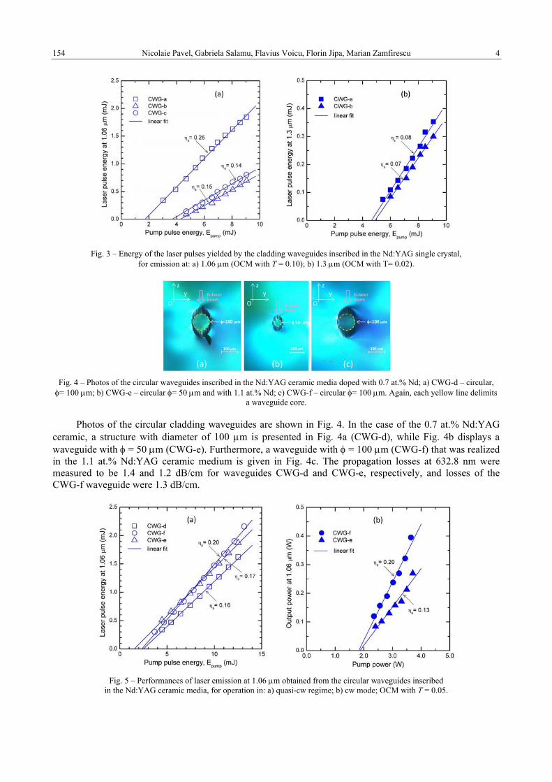
Nicolaie Pavel, Gabriela Salamu, Flavius Voicu, Florin Jipa, Marian Zamfirescu 4 154
Fig. 3 – Energy of the laser pulses yielded by the cladding waveguides inscribed in the Nd:YAG single crystal,
for emission at: a) 1.06 µm (OCM with T = 0.10); b) 1.3 µm (OCM with T= 0.02).
Fig. 4 – Photos of the circular waveguides inscribed in the Nd:YAG ceramic media doped with 0.7 at.% Nd; a) CWG-d – circular,
φ= 100 µm; b) CWG-e – circular φ= 50 µm and with 1.1 at.% Nd; c) CWG-f – circular φ= 100 µm. Again, each yellow line delimits a waveguide core.
Photos of the circular cladding waveguides are shown in Fig. 4. In the case of the 0.7 at.% Nd:YAG ceramic, a structure with diameter of 100 µm is presented in Fig. 4a (CWG-d), while Fig. 4b displays a waveguide with φ = 50 µm (CWG-e). Furthermore, a waveguide with φ = 100 µm (CWG-f) that was realized in the 1.1 at.% Nd:YAG ceramic medium is given in Fig. 4c. The propagation losses at 632.8 nm were measured to be 1.4 and 1.2 dB/cm for waveguides CWG-d and CWG-e, respectively, and losses of the CWG-f waveguide were 1.3 dB/cm.
Fig. 5 – Performances of laser emission at 1.06 µm obtained from the circular waveguides inscribed
in the Nd:YAG ceramic media, for operation in: a) quasi-cw regime; b) cw mode; OCM with T = 0.05.
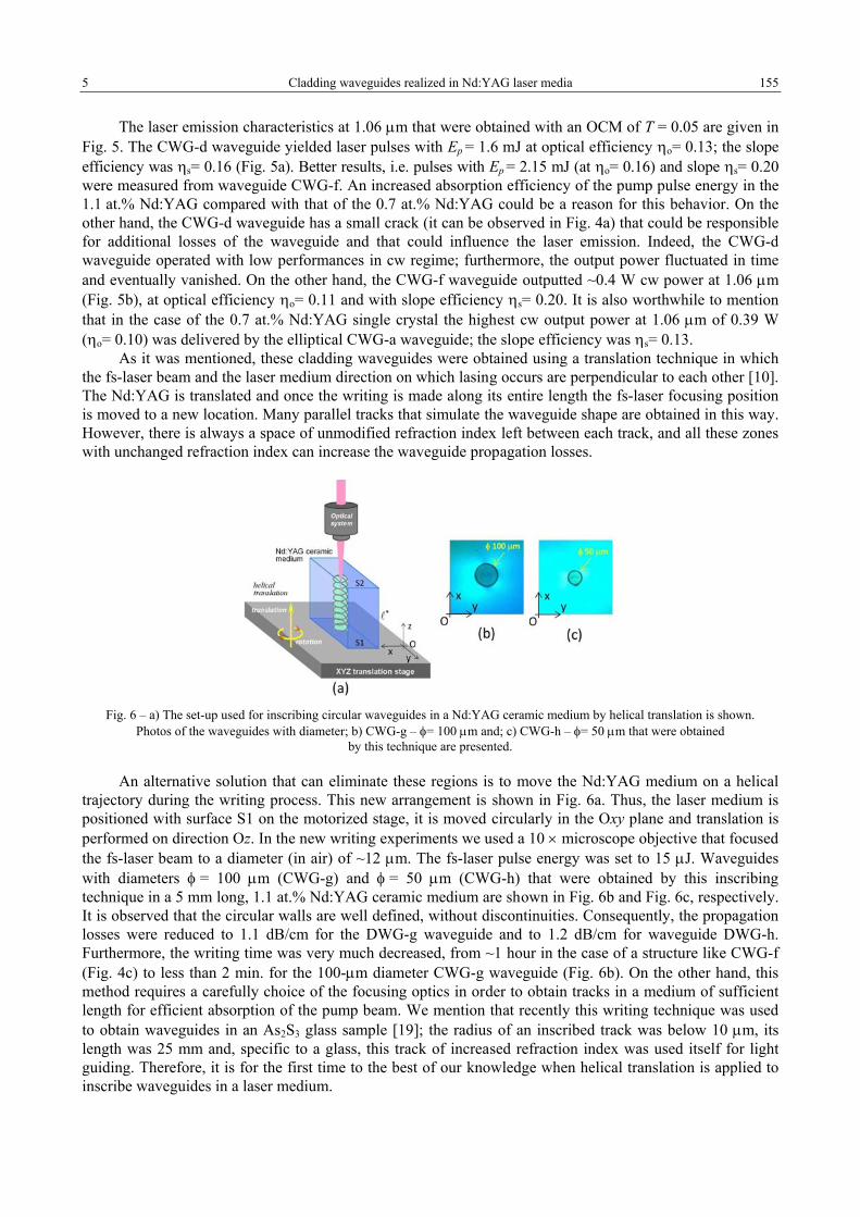
5 Cladding waveguides realized in Nd:YAG laser media 155
The laser emission characteristics at 1.06 µm that were obtained with an OCM of T = 0.05 are given in Fig. 5. The CWG-d waveguide yielded laser pulses with Ep = 1.6 mJ at optical efficiency ηo= 0.13; the slope efficiency was ηs= 0.16 (Fig. 5a). Better results, i.e. pulses with Ep = 2.15 mJ (at ηo= 0.16) and slope ηs= 0.20 were measured from waveguide CWG-f. An increased absorption efficiency of the pump pulse energy in the 1.1 at.% Nd:YAG compared with that of the 0.7 at.% Nd:YAG could be a reason for this behavior. On the other hand, the CWG-d waveguide has a small crack (it can be observed in Fig. 4a) that could be responsible for additional losses of the waveguide and that could influence the laser emission. Indeed, the CWG-d waveguide operated with low performances in cw regime; furthermore, the output power fluctuated in time and eventually vanished. On the other hand, the CWG-f waveguide outputted ~0.4 W cw power at 1.06 µm (Fig. 5b), at optical efficiency ηo= 0.11 and with slope efficiency ηs= 0.20. It is also worthwhile to mention that in the case of the 0.7 at.% Nd:YAG single crystal the highest cw output power at 1.06 µm of 0.39 W (ηo= 0.10) was delivered by the elliptical CWG-a waveguide; the slope efficiency was ηs= 0.13.
As it was mentioned, these cladding waveguides were obtained using a translation technique in which the fs-laser beam and the laser medium direction on which lasing occurs are perpendicular to each other [10]. The Nd:YAG is translated and once the writing is made along its entire length the fs-laser focusing position is moved to a new location. Many parallel tracks that simulate the waveguide shape are obtained in this way. However, there is always a space of unmodified refraction index left between each track, and all these zones with unchanged refraction index can increase the waveguide propagation losses.
Fig. 6 – a) The set-up used for inscribing circular waveguides in a Nd:YAG ceramic medium by helical translation is shown.
Photos of the waveguides with diameter; b) CWG-g – φ= 100 µm and; c) CWG-h – φ= 50 µm that were obtained by this technique are presented.
An alternative solution that can eliminate these regions is to move the Nd:YAG medium on a helical trajectory during the writing process. This new arrangement is shown in Fig. 6a. Thus, the laser medium is positioned with surface S1 on the motorized stage, it is moved circularly in the Oxy plane and translation is performed on direction Oz. In the new writing experiments we used a 10 × microscope objective that focused the fs-laser beam to a diameter (in air) of ~12 µm. The fs-laser pulse energy was set to 15 µJ. Waveguides with diameters φ = 100 µm (CWG-g) and φ = 50 µm (CWG-h) that were obtained by this inscribing technique in a 5 mm long, 1.1 at.% Nd:YAG ceramic medium are shown in Fig. 6b and Fig. 6c, respectively. It is observed that the circular walls are well defined, without discontinuities. Consequently, the propagation losses were reduced to 1.1 dB/cm for the DWG-g waveguide and to 1.2 dB/cm for waveguide DWG-h. Furthermore, the writing time was very much decreased, from ~1 hour in the case of a structure like CWG-f (Fig. 4c) to less than 2 min. for the 100-µm diameter CWG-g waveguide (Fig. 6b). On the other hand, this method requires a carefully choice of the focusing optics in order to obtain tracks in a medium of sufficient length for efficient absorption of the pump beam. We mention that recently this writing technique was used to obtain waveguides in an As2S3 glass sample [19]; the radius of an inscribed track was below 10 µm, its length was 25 mm and, specific to a glass, this track of increased refraction index was used itself for light guiding. Therefore, it is for the first time to the best of our knowledge when helical translation is applied to inscribe waveguides in a laser medium.

Nicolaie Pavel, Gabriela Salamu, Flavius Voicu, Florin Jipa, Marian Zamfirescu 6 156
Characteristics of the laser emission at 1.06 µm recorded from these two waveguides under quasi-cw pumping are shown in Fig. 7a (the best performances were obtained with an OCM of transmission T = 0.05). Pulses with energy Ep = 2.65 mJ (for Epump = 13.1 mJ, then with ηo= 0.20) and slope ηs=0.23 were obtained from waveguide CWG-g. The CWG-h waveguide improved the pulse energy to Ep = 3.45 mJ and slope ηs increased to 0.29. On the other hand, when the pump was made in cw mode the CWG-g waveguide yielded 0.48 W power at 1.06 µm with slope ηs= 0.24; the maximum pump power was 3.7 W. The CWG-h waveguide increased the cw power at 0.51 W, with slope ηs= 0.25. An explanation of these improvements could be the fact that although less pump light is coupled into CWG-h (φ= 50 µm) than in CWG-g (φ= 100 µm) a better overlap between the pumped volume and the laser beam is obtained in the CWG-h waveguide.
Figure 7b compares the performances of laser emission at 1.3 µm recorded from the 100-µm diameter CWG-f waveguide that was inscribed by the classical translation technique and the CWG-g waveguide (of the same dimension) that was obtained by the helical movement of the 1.1 at.% Nd:YAG ceramic medium. Laser pulses with energy Ep = 1.15 mJ at slope ηs= 0.12 were obtained from CWG-g; these results were better than the laser pulses of energy Ep = 1.05 mJ and slope ηs= 0.11 that were yielded by the CWG-f waveguide. Finally, Table 1 summarizes the energy of laser pulses emitted at 1.06 and 1.3 µm by the various waveguides that were characterized in this work.
Fig. 7 – a) Laser pulse energy at 1.06 µm obtained from the waveguides inscribed by helical movement of the 1.1 t.% Nd:YAG ceramic (OCM with T = 0.05); b) comparison of Ep at 1.3 µm delivered by the waveguides with φ = 100 µm that were written
by the two techniques in 1.1 at.% Nd:YAG ceramics (OCM with T = 0.03).
Table 1
The main results reported in this work for laser emission at 1.06 and 1.3 µm from the cladding waveguides that were inscribed in Nd:YAG single crystal or ceramic media are given. CWG-a (elliptical, 120 µm × 165 µm); CWG-b (circular, φ = 80 µm); CWG-c
(rectangular, 30×80 µm2); CWG-d, CWG-f and CWG-g (circular, φ = 100 µm); CWG-e and CWG-h (circular, φ = 50 µm). The pump was made in quasi-cw regime with a fiber-coupled diode laser at 807 nm
λem= 1.06 µm λem= 1.3 µm
Nd:YAG The
cladding waveguide
Propagation losses
(dB/cm)
Laser pulse energy Ep (mJ)
Optical efficiency
ηo
Slope efficiency
ηs
Laser pulse energy Ep (mJ)
Optical efficiency
ηo
Slope efficiency
ηs 0.7 at.% Nd,
single crystal
CWG-a CWG-b CWG-c
1.3 1.6 2.2
1.85 0.7 0.8
0.20 0.08 0.09
0.25 0.15 0.14
0.35 0.3 -
0.04 0.03
-
0.08 0.07
-
0.7 at.% Nd, ceramic
CWG-d CWG-e
1.4 1.2
1.6 1.8
0.13 0.15
0.16 0.17
- 1.2
- 0.09
- 0.12
1.1 at.% Nd, ceramic CWG-f 1.3 2.15 0.16 0.20 0.9 0.07 0.11
1.1 at.% Nd, ceramic
CWG-g CWG-h
1.1 1.2
2.65 3.45
0.20 0.26
0.23 0.29
1.15 1.05
~0.09 0.08
0.12 0.11
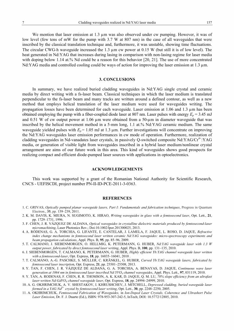
7 Cladding waveguides realized in Nd:YAG laser media 157
We mention that laser emission at 1.3 µm was also observed under cw pumping. However, it was of low level (few tens of mW for the pump with 3.7 W at 807 nm) in the case of all waveguides that were inscribed by the classical translation technique and, furthermore, it was unstable, showing time fluctuations. The circular CWG-h waveguide increased the 1.3 µm cw power at 0.15 W (but still it is of low level). The heat generated in Nd:YAG that increases during lasing in comparison with non-lasing regime for laser media with doping below 1.14 at.% Nd could be a reason for this behavior [20, 21]. The use of more concentrated Nd:YAG media and controlled cooling could be ways of action for improving the laser emission at 1.3 µm.
3. CONCLUSIONS
In summary, we have realized buried cladding waveguides in Nd:YAG single crystal and ceramic media by direct writing with a fs-laser beam. Classical techniques in which the laser medium is translated perpendicular to the fs-laser beam and many tracks are written around a defined contour, as well as a new method that employs helical translation of the laser medium were used for waveguides writing. The propagation losses have been determined for each waveguide. Laser emission at 1.06 and 1.3 µm has been obtained employing the pump with a fiber-coupled diode laser at 807 nm. Laser pulses with energy Ep = 3.45 mJ and 0.51 W of cw output power at 1.06 µm were obtained from a 50-µm in diameter waveguide that was inscribed by the helical movement method in a 5-mm long, 1.1 at.% Nd:YAG ceramic medium. The same waveguide yielded pulses with Ep = 1.05 mJ at 1.3 µm. Further investigations will concentrate on improving the Nd:YAG waveguides laser emission performances in cw mode of operation. Furthermore, realization of cladding waveguides in Nd-vanadates laser crystals, in passively Q-switched composite Nd:YAG/Cr4+:YAG media, or generation of visible light from waveguides inscribed in a hybrid laser medium/nonlinear crystal arrangement are aims of our future work in this area. This kind of waveguides shows good prospects for realizing compact and efficient diode-pumped laser sources with applications in optoelectronics.
ACKNOWLEDGEMENTS
This work was supported by a grant of the Romanian National Authority for Scientific Research, CNCS - UEFISCDI, project number PN-II-ID-PCE-2011-3-0363.
REFERENCES
1. C. GRIVAS, Optically pumped planar waveguide lasers, Part I: Fundamentals and fabrication techniques, Progress in Quantum Electron., 35, pp. 159–239, 2011.
2. K. M. DAVIS, K. MIURA, N. SUGIMOTO, K. HIRAO, Writing waveguides in glass with a femtosecond laser, Opt. Lett., 21, pp. 1729–1731, 1996.
3. F. CHEN, J. R. VÁZQUEZ DE ALDANA, Optical waveguides in crystalline dielectric materials produced by femtosecond-laser micromachining, Laser Photonics Rev.; Doi:10.1002/lpor.201300025, 2013.
4. A. RÓDENAS, G. A. TORCHIA, G. LIFANTE, E. CANTELAR, J. LAMELA, F. JAQUE, L. ROSO, D. JAQUE, Refractive index change mechanisms in femtosecond laser written ceramic Nd:YAG waveguides: micro-spectroscopy experiments and beam propagation calculations, Appl. Phys. B, 95, pp. 85–96, 2009.
5. T. CALMANO, J. SIEBENMORGEN, O. HELLMIG, K. PETERMANN, G. HUBER, Nd:YAG waveguide laser with 1.3 W output power, fabricated by direct femtosecond laser writing, Appl. Phys. B, 100, pp. 131–135, 2010.
6. J. SIEBENMORGEN, T. CALMANO, K. PETERMANN, G. HUBER, Highly efficient Yb:YAG channel waveguide laser written with a femtosecond-laser, Opt. Express, 18, pp. 16035–16041, 2010 .
7. T. CALMANO, A.-G. PASCHKE, S. MÜLLER, C. KRÄNKEL, G. HUBER, Curved Yb:YAG waveguide lasers, fabricated by femtosecond laser inscription, Opt. Express, 21, pp. 25501–25508, 2013.
8. Y. TAN, F. CHEN, J. R. VÁZQUEZ DE ALDANA, G. A. TORCHIA, A. BENAYAS, D. JAQUE, Continuous wave laser generation at 1064 nm in femtosecond laser inscribed Nd:YVO4 channel waveguides, Appl. Phys. Lett., 97, 031119, 2010.
9. Y. TAN, A. RODENAS, F. CHEN, R. R. THOMSON, A. K. KAR, D. JAQUE, Q. M. LU, 70% slope efficiency from an ultrafast laser-written Nd:GdVO4 channel waveguide laser, Opt. Express, 18, pp. 24994–24999, 2010.
10. A. G. OKHRIMCHUK, A. V. SHESTAKOV, I. KHRUSHCHEV, J. MITCHELL, Depressed cladding, buried waveguide laser formed in a YAG:Nd3+ crystal by femtosecond laser writing, Opt. Lett., 30, pp. 2248–2250, 2005.
11. A. OKHRIMCHUK, Femtosecond Fabrication of Waveguides, in Ion-Doped Laser Crystals, Coherence and Ultrashort Pulse Laser Emission, Dr. F. J. Duarte (Ed.), ISBN: 978-953-307-242-5, InTech; DOI: 10.5772/12885, 2010.

Nicolaie Pavel, Gabriela Salamu, Flavius Voicu, Florin Jipa, Marian Zamfirescu 8 158
12. A. OKHRIMCHUK, V. MEZENTSEV, A. SHESTAKOV, I. BENNION, Low loss depressed cladding waveguide inscribed in YAG:Nd single crystal by femtosecond laser pulses, Opt. Express, 20, pp. 3832–3843, 2012.
13. H. LIU, Y. JIA, J. R. VÁZQUEZ DE ALDANA, D. JAQUE, F. CHEN, Femtosecond laser inscribed cladding waveguides in Nd:YAG ceramics: Fabrication, fluorescence imaging and laser performance, Opt. Express, 20, pp. 18620–18629, 2012.
14. H. LIU, F. CHEN, J. R. VÁZQUEZ DE ALDANA, D. JAQUE, Femtosecond-laser inscribed double-cladding waveguides in Nd:YAG crystal: a promising prototype for integrated lasers, Opt. Lett., 38, pp. 3294–3297, 2013.
15. S. MÜLLER, T. CALMANO, P. METZ, N.-O. HANSEN, C. KRÄNKEL, G. HUBER, Femtosecond-laser-written diode-pumped Pr:LiYF4 waveguide laser, Opt. Lett., 37, pp. 5223–5225, 2012.
16. Y. REN, G. BROWN, A. RÓDENAS, S. BEECHER, F. CHEN, A. K. KAR, Mid-infrared waveguide lasers in rare-earth-doped YAG, Opt. Lett., 37, pp. 3339–3341, 2012.
17. D. G. LANCASTER, S. GROSS, H. EBENDORFF-HEIDEPRIEM, K. KUAN, T. M. MONRO, M. AMS, A. FUERBACH, M. J. WITHFORD, Fifty percent internal slope efficiency femtosecond direct-written Tm³:ZBLAN waveguide laser, Opt. Lett., 36, pp. 1587–1589, 2011.
18. N. PAVEL, G. SALAMU, F. VOICU, F. JIPA, M. ZAMFIRESCU, T. DASCALU, Efficient laser emission in diode-pumped Nd:YAG buried waveguides realized by direct femtosecond-laser writing, Laser Phys. Lett., 10, 095802, 2013.
19. O. CAULIER, D.-L. COQ, E. BYCHKOV, P. MASSELIN, Direct laser writing of buried waveguide in As2S3 glass using a helical sample translation, Opt. Lett., 38, pp. 4212–4215, 2013.
20. N. PAVEL, V. LUPEI, T. TAIRA, 1.34-µm efficient laser emission in highly-doped Nd:YAG under 885-nm diode pumping, Opt. Express, 13, pp. 7948–7953, 2005.
21. N. PAVEL, V. LUPEI, J. SAIKAWA, T. TAIRA, H. KAN, Neodymium concentration dependence of 0.94, 1.06 and 1.34 µm laser emission and of heating effects under 809 and 885-nm diode laser pumping of Nd:YAG, Appl. Phys. B, 82, pp. 599–605, 2006.
Received February 20, 2014
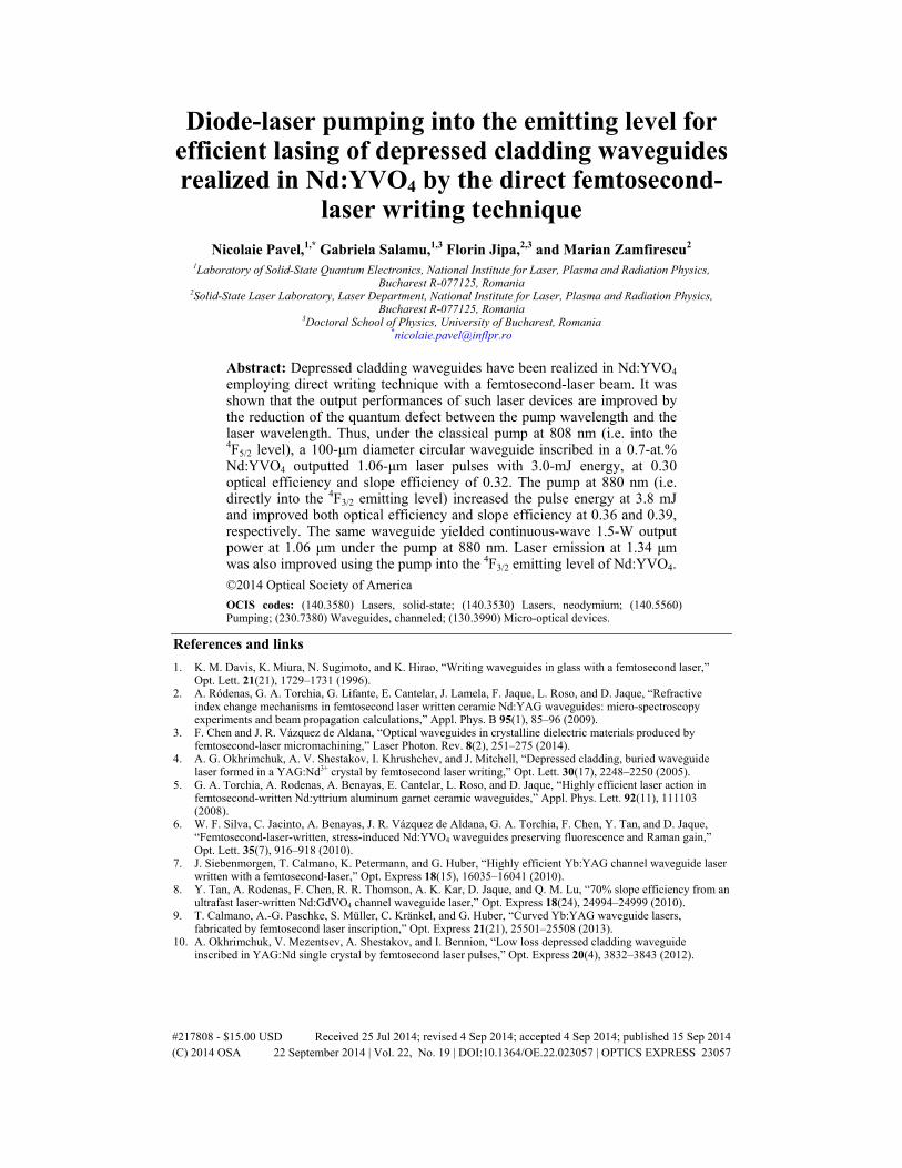
Diode-laser pumping into the emitting level for efficient lasing of depressed cladding waveguides realized in Nd:YVO4 by the direct femtosecond-
laser writing technique Nicolaie Pavel,1,* Gabriela Salamu,1,3 Florin Jipa,2,3 and Marian Zamfirescu2
1Laboratory of Solid-State Quantum Electronics, National Institute for Laser, Plasma and Radiation Physics, Bucharest R-077125, Romania
2Solid-State Laser Laboratory, Laser Department, National Institute for Laser, Plasma and Radiation Physics, Bucharest R-077125, Romania
3Doctoral School of Physics, University of Bucharest, Romania *[email protected]
Abstract: Depressed cladding waveguides have been realized in Nd:YVO4 employing direct writing technique with a femtosecond-laser beam. It was shown that the output performances of such laser devices are improved by the reduction of the quantum defect between the pump wavelength and the laser wavelength. Thus, under the classical pump at 808 nm (i.e. into the 4F5/2 level), a 100-μm diameter circular waveguide inscribed in a 0.7-at.% Nd:YVO4 outputted 1.06-μm laser pulses with 3.0-mJ energy, at 0.30 optical efficiency and slope efficiency of 0.32. The pump at 880 nm (i.e. directly into the 4F3/2 emitting level) increased the pulse energy at 3.8 mJ and improved both optical efficiency and slope efficiency at 0.36 and 0.39, respectively. The same waveguide yielded continuous-wave 1.5-W output power at 1.06 μm under the pump at 880 nm. Laser emission at 1.34 μm was also improved using the pump into the 4F3/2 emitting level of Nd:YVO4. ©2014 Optical Society of America OCIS codes: (140.3580) Lasers, solid-state; (140.3530) Lasers, neodymium; (140.5560) Pumping; (230.7380) Waveguides, channeled; (130.3990) Micro-optical devices.
References and links
1. K. M. Davis, K. Miura, N. Sugimoto, and K. Hirao, “Writing waveguides in glass with a femtosecond laser,” Opt. Lett. 21(21), 1729–1731 (1996).
2. A. Ródenas, G. A. Torchia, G. Lifante, E. Cantelar, J. Lamela, F. Jaque, L. Roso, and D. Jaque, “Refractive index change mechanisms in femtosecond laser written ceramic Nd:YAG waveguides: micro-spectroscopy experiments and beam propagation calculations,” Appl. Phys. B 95(1), 85–96 (2009).
3. F. Chen and J. R. Vázquez de Aldana, “Optical waveguides in crystalline dielectric materials produced by femtosecond-laser micromachining,” Laser Photon. Rev. 8(2), 251–275 (2014).
4. A. G. Okhrimchuk, A. V. Shestakov, I. Khrushchev, and J. Mitchell, “Depressed cladding, buried waveguide laser formed in a YAG:Nd3+ crystal by femtosecond laser writing,” Opt. Lett. 30(17), 2248–2250 (2005).
5. G. A. Torchia, A. Rodenas, A. Benayas, E. Cantelar, L. Roso, and D. Jaque, “Highly efficient laser action in femtosecond-written Nd:yttrium aluminum garnet ceramic waveguides,” Appl. Phys. Lett. 92(11), 111103 (2008).
6. W. F. Silva, C. Jacinto, A. Benayas, J. R. Vázquez de Aldana, G. A. Torchia, F. Chen, Y. Tan, and D. Jaque, “Femtosecond-laser-written, stress-induced Nd:YVO4 waveguides preserving fluorescence and Raman gain,” Opt. Lett. 35(7), 916–918 (2010).
7. J. Siebenmorgen, T. Calmano, K. Petermann, and G. Huber, “Highly efficient Yb:YAG channel waveguide laser written with a femtosecond-laser,” Opt. Express 18(15), 16035–16041 (2010).
8. Y. Tan, A. Rodenas, F. Chen, R. R. Thomson, A. K. Kar, D. Jaque, and Q. M. Lu, “70% slope efficiency from an ultrafast laser-written Nd:GdVO4 channel waveguide laser,” Opt. Express 18(24), 24994–24999 (2010).
9. T. Calmano, A.-G. Paschke, S. Müller, C. Kränkel, and G. Huber, “Curved Yb:YAG waveguide lasers, fabricated by femtosecond laser inscription,” Opt. Express 21(21), 25501–25508 (2013).
10. A. Okhrimchuk, V. Mezentsev, A. Shestakov, and I. Bennion, “Low loss depressed cladding waveguide inscribed in YAG:Nd single crystal by femtosecond laser pulses,” Opt. Express 20(4), 3832–3843 (2012).
#217808 - $15.00 USD Received 25 Jul 2014; revised 4 Sep 2014; accepted 4 Sep 2014; published 15 Sep 2014(C) 2014 OSA 22 September 2014 | Vol. 22, No. 19 | DOI:10.1364/OE.22.023057 | OPTICS EXPRESS 23057
11. H. Liu, Y. Jia, J. R. Vázquez de Aldana, D. Jaque, and F. Chen, “Femtosecond laser inscribed cladding waveguides in Nd:YAG ceramics: Fabrication, fluorescence imaging and laser performance,” Opt. Express 20(17), 18620–18629 (2012).
12. D. G. Lancaster, S. Gross, H. Ebendorff-Heidepriem, K. Kuan, T. M. Monro, M. Ams, A. Fuerbach, and M. J. Withford, “Fifty percent internal slope efficiency femtosecond direct-written Tm³⁺:ZBLAN waveguide laser,” Opt. Lett. 36(9), 1587–1589 (2011).
13. Y. Ren, G. Brown, A. Ródenas, S. Beecher, F. Chen, and A. K. Kar, “Mid-infrared waveguide lasers in rare-earth-doped YAG,” Opt. Lett. 37(16), 3339–3341 (2012).
14. J. R. Macdonald, S. J. Beecher, P. A. Berry, G. Brown, K. L. Schepler, and A. K. Kar, “Efficient mid-infrared Cr:ZnSe channel waveguide laser operating at 2486 nm,” Opt. Lett. 38(13), 2194–2196 (2013).
15. J. R. Macdonald, S. J. Beecher, A. Lancaster, P. A. Berry, K. L. Schepler, S. B. Mirov, and A. K. Kar, “Compact Cr:ZnS channel waveguide laser operating at 2333 nm,” Opt. Express 22(6), 7052–7057 (2014).
16. S. Müller, T. Calmano, P. Metz, N.-O. Hansen, C. Kränkel, and G. Huber, “Femtosecond-laser-written diode-pumped Pr:LiYF4 waveguide laser,” Opt. Lett. 37(24), 5223–5225 (2012).
17. G. Salamu, F. Jipa, M. Zamfirescu, and N. Pavel, “Laser emission from diode-pumped Nd:YAG ceramic waveguide lasers realized by direct femtosecond-laser writing technique,” Opt. Express 22(5), 5177–5182 (2014).
18. G. Salamu, F. Jipa, M. Zamfirescu, and N. Pavel, “Cladding waveguides realized in Nd:YAG ceramic by direct femtosecond-laser writing with a helical movement technique,” Opt. Mater. Express 4(4), 790–797 (2014).
19. N. Pavel, G. Salamu, F. Voicu, F. Jipa, and M. Zamfirescu, “Cladding waveguides realized in Nd:YAG laser media by direct writing with a femtosecond-laser beam,” Proc. Romanian Acad. Ser. A: Math. Phys. Tech. Sci. Inf. Sci. 15(2), 151–158 (2014).
20. T. Taira, “RE3+-ion-doped YAG ceramics,” IEEE J. Sel. Top. Quantum Electron. 13(3), 798–809 (2007). 21. Y. Jia, F. Chen, and J. R. Vázquez de Aldana, “Efficient continuous-wave laser operation at 1064 nm in
Nd:YVO4 cladding waveguides produced by femtosecond laser inscription,” Opt. Express 20(15), 16801–16806 (2012).
22. H. Liu, J. R. Vázquez de Aldana, and F. Chen, “Efficient lasing in Nd:GdVO4 depressed cladding waveguides produced by femtosecond laser writing,” Proc. SPIE 9133, 913315 (2014).
23. R. Newman, “Excitation of the Nd3+ fluorescence in CaWO4 by recombination radiation in GaAs,” J. Appl. Phys. 34(2), 437 (1963).
24. R. Lavi, S. Jackel, Y. Tzuk, M. Winik, E. Lebiush, M. Katz, and I. Paiss, “Efficient pumping scheme for neodymium-doped materials by direct excitation of the upper lasing level,” Appl. Opt. 38(36), 7382–7385 (1999).
25. V. Lupei, N. Pavel, and T. Taira, “Highly efficient laser emission in concentrated Nd:YVO4 components under direct pumping into the emitting level,” Opt. Commun. 201(4–6), 431–435 (2002).
26. Y. Sato, T. Taira, N. Pavel, and V. Lupei, “Laser operation with near quantum-defect slope efficiency in Nd:YVO4 under direct pumping into the emitting level,” Appl. Phys. Lett. 82(6), 844–846 (2003).
27. V. Lupei, N. Pavel, Y. Sato, and T. Taira, “Highly efficient 1063-nm continuous-wave laser emission in Nd:GdVO4.,” Opt. Lett. 28(23), 2366–2368 (2003).
28. Y. Sato and T. Taira, “Saturation factors of pump absorption in solid-state lasers,” IEEE J. Quantum Electron. 40(3), 270–280 (2004).
29. V. Lupei, A. Lupei, S. Georgescu, T. Taira, Y. Sato, and A. Ikesue, “The effect of Nd concentration on the spectroscopic and emission decay properties of highly-doped Nd:YAG ceramics,” Phys. Rev. B 64(9), 092102 (2001).
30. N. Pavel, V. Lupei, J. Saikawa, T. Taira, and H. Kan, “Neodymium concentration dependence of 0.94, 1.06 and 1.34 μm laser emission and of heating effects under 809 and 885-nm diode laser pumping of Nd:YAG,” Appl. Phys. B 82(4), 599–605 (2006).
31. H. Liu, Y. Tan, J. R. Vázquez de Aldana, and F. Chen, “Efficient laser emission from cladding waveguide inscribed in Nd:GdVO4 crystal by direct femtosecond laser writing,” Opt. Lett. 39(15), 4553–4556 (2014).
1. Introduction
The inscribing process of various structures in amorphous or crystalline materials is nowadays recognized as a suitable and powerful tool for fabrication of various miniature components for integrated optical devices. Using this technique, localized (at micrometer scale) changes of the refractive index are induced by a femtosecond (fs)-laser beam [1, 2]. Of great interest for optoelectronics are the waveguide lasers. In general, such a device possesses a low threshold of emission due to a small size of the pump beam, whereas the high overlap between the pump beam and the laser beam along the entire medium length leads to good output performance.
Waveguides were inscribed by fs-laser writing in many glasses, laser crystals or nonlinear media [3]. Among them the depressed cladding waveguides, which were proposed and for the first time realized by Okhrimchuk et al [4], consist of a region of unmodified medium that is surrounded by a large number of inscribed tracks with lower refractive index. Contrary to the
#217808 - $15.00 USD Received 25 Jul 2014; revised 4 Sep 2014; accepted 4 Sep 2014; published 15 Sep 2014(C) 2014 OSA 22 September 2014 | Vol. 22, No. 19 | DOI:10.1364/OE.22.023057 | OPTICS EXPRESS 23058
‘double-line’ waveguides, which are limited at 10 μm to 20 μm separation between tracks and that allow propagation of linearly-polarized beams [5–9], a depressed cladding waveguide can be realized with a large cross section. Furthermore, the waveguide core can be shaped to allow the pump with array or fiber-coupled diode lasers. Some examples are the circular, rectangular, trapezoidal or hexagonal waveguides written in Nd:YAG [4, 10, 11], circular in the mid-infrared emitting Tm [12, 13] and polycrystalline Cr:ZnS [14, 15] lasers, or rhombic in Pr:YLiF4 with emission into the visible spectrum [16]. Recently, we have used the pump with a fiber-coupled diode laser to achieve efficient laser emission from circular depressed cladding waveguides fabricated in Nd:YAG by the fs-laser writing method [17–19].
Nd-vanadate crystals have suitable spectroscopic characteristics (like high absorption and emission cross sections) and good thermal properties that recommend these media for efficient, miniature lasers [20]. Until now, circular depressed cladding waveguides were inscribed in Nd:YVO4 [21] and circular depressed double-cladding waveguides have been realized in Nd:GdVO4 [22]. Furthermore, efficient 1.06-μm laser emission with slope efficiency (versus the absorbed pump power) higher that 50% and output power of few-hundreds of mW was achieved from these waveguides using the pump at 808 nm with tunable, linearly-polarized Ti:sapphire lasers [21, 22].
In this work we report on realization of depressed cladding waveguides in Nd:YVO4 by the direct fs-laser writing technique and obtain efficient laser emission at 1.06 μm and 1.34 μm under the pump with a fiber-coupled diode laser. Thus, using classical pump at 808 nm (i.e. into the highly absorbing 4F5/2 emitting level), a 100-μm in diameter cladding waveguide that was inscribed in a 4.8-mm long, 0.7-at.% Nd:YVO4 delivered laser pulses with 3.0-mJ energy (Ep); with respect to the absorbed pump pulse energy, the optical-to-optical efficiency (ηoa) and the slope efficiency (ηsa) were 0.30 and 0.32, respectively. The waveguide outputted 0.9-W continuous-wave (cw) power at 1.06 μm with efficiency ηoa = 0.14 and slope ηsa = 0.19.
In order to increase the waveguide performances we have used the pump at 880 nm, directly into the 4F3/2 emitting level [23–27]. Thus, by decreasing the quantum defect between the pump wavelength and the laser wavelength and by making use of the Nd:YVO4 high absorption efficiency at 880 nm, which is about 70% of that corresponding to the 808-nm absorption [20, 25, 26], systematic improvements of the laser emission characteristics have been obtained. For the pump at 880 nm the same waveguide outputted laser pulses with Ep = 3.8 mJ at increased optical efficiency ηoa = 0.36 and slope ηsa = 0.39; furthermore, the cw output power increased at 1.5 W (with ηoa = 0.27 and ηsa = 0.28). Improvements of the laser emission performances at 1.34 μm were also obtained for the pump at 880 nm in comparison with the 808-nm pump. The measurements of the Nd:YVO4 temperature prove that less heat is generated in the laser crystal for the pump directly into the 4F3/2 emitting level. This is the first time when the pump at 880 nm is applied to fs-laser inscribed waveguides and could be a good approach for fabricating efficient integrated waveguide lasers pumped by diode lasers.
2. Waveguides fabrication and characterization: experimental conditions
For inscribing tracks in Nd:YVO4 we used the same facility, as the one in our previous reports [17–19]. Thus, the laser beam at 775 nm with 200-fs duration, 2-kHz repetition rate and energy up to 0.6 mJ was delivered by a Clark CPA-2101 chirped-pulsed amplified system. A combination of half-wave plate, a polarizer and a neutral filter was used to vary the fs-laser beam energy. Focusing into the laser medium was made with a 20× microscope objective of numerical aperture NA = 0.30; the beam diameter at the waist location (in air) was ~5.0 μm.
The laser crystals were three a-cut Nd:YVO4 media with 0.5-at.%, 0.7-at.% and 1.0-at.% Nd doping; the thickness t (Oz axis) and width w (Ox axis) were 3.0 mm and 6.0 mm, respectively. Each crystal was positioned on a XYZ motorized stage that was translated along axis Oy (corresponding to the crystal length ℓ) at a speed of 50 μm/s. Circular cladding waveguides of 100-μm diameter were obtained by inscribing parallel tracks (that were positioned ~5 μm apart each other) around circular contours. A square waveguide (80 μm ×
#217808 - $15.00 USD Received 25 Jul 2014; revised 4 Sep 2014; accepted 4 Sep 2014; published 15 Sep 2014(C) 2014 OSA 22 September 2014 | Vol. 22, No. 19 | DOI:10.1364/OE.22.023057 | OPTICS EXPRESS 23059

80 μm) was also realized in the 0.5-at.% Nd:YVO4 crystal, to prove the writing method versatility. The waveguides were centered 500-μm below each w × ℓ medium surface. Through successive attempts (and by monitoring the writing process with a video camera), tracks were obtained by keeping the fs-laser pulse energy slightly below 0.3 μJ. The lateral sides of each Nd:YVO4 crystal were polished after the writing process. Thus, the final length of the 0.5-at.%, 0.7 at.% and 1.0-at.% Nd:YVO4 crystals was 7.2 mm, 4.8 mm and 3.6 mm, respectively.
The depressed circular waveguides will be denoted by CWG-1 (0.5-at.% Nd:YVO4), CWG-2 (0.7-at.% Nd:YVO4) and CWG-3 (1.0-at.% Nd:YVO4), whereas SWG (0.7-at.% Nd:YVO4) will stand for the square-shaped waveguide. Microscope photos of waveguides CWG-1 and SWG are shown in Fig. 1(a) and Fig. 1(b), respectively. It can be observed that the inscribed tracks are clear with no visible cracks. The propagation losses were evaluated by coupling a 632.8-nm HeNe laser into each waveguide and by measuring the power of the transmitted light. After extracting the coupling efficiency (that was evaluated to unity) and the Fresnel losses, we concluded that propagation losses for the HeNe beam polarized parallel to the inscribed tracks (axis Oz in Fig. 1(a)) were 2.4 dB/cm for CWG-1, in the 1.5 to 1.7 dB/cm range for CWG-2 and CWG-3, whereas the square SWG waveguide has a little higher losses (3.4 dB/cm). An increase of the losses, between 5.5 to 6.0 dB/cm for the circular waveguides and nearly 6.3 dB/cm for the square-shape waveguide, was observed when the HeNe beam was polarized perpendicular to the inscribed tracks; this could be attributed to some leakage of the light through the crystal left unmodified between the tracks [18].
Fig. 1. Microscope photos of the depressed cladding waveguides inscribed in the 0.5-at.% Nd:YVO4 crystal are shown: (a) CWG-1, circular with diameter of 100 μm and (b) SWG, 80 μm × 80 μm square; the white dashed lines indicate the waveguides’ boundary. Fluorescence images of the waveguides are presented: (c) CWG-1, (d) CWG-2, inscribed in the 0.7-at.% Nd:YVO4, (e) CWG-3, written in the 1.0-at.% Nd:YVO4, and (f) the waveguide SWG.
The optical pump for the laser emission experiments was made with fiber-coupled diode lasers (LIMO Co., Germany) at 808 nm and at 880 nm (with no polarization control of the pump beam). Each fiber end (both with diameter of 100 μm and NA = 0.22) was imaged into a waveguide through a collimating lens of 50-mm focal length and a 30-mm focal length focusing lens. The diodes were operated in quasi-cw regime (1.0-ms pump pulse duration and up to 100-Hz repetition rate), as well as in cw mode. The resonator was linear and consisted of two plane mirrors that were positioned very close to each Nd:YVO4 crystal sides. The rear mirror (the one facing the pump line) was coated high reflectivity HR (reflectivity, R> 0.998) at the laser emission wavelength (λem) of 1.06 μm or 1.34 μm and with high transmission, HT (transmission, T> 0.98) at the pump wavelengths (λp) of 808 nm and 880 nm. For the emission at 1.06 μm several out-coupling mirrors (OCM) with T between 0.01 and 0.10 were used. On the other hand, in the case of lasing at 1.34 μm the OCM had a specified T (between 0.02 and 0.07) at this wavelength, and it was also coated HT (T> 0.95) at 1.06 μm in order to suppress emission at this high-gain line. In addition, a spectrometer was used to check the absence of the 1.06-μm line during emission at 1.34 μm. Fluorescence images of the waveguides (which were recorded with a 190-1100 nm spectral range Spiricon camera, model SP620U) are given in Fig. 1(c) for waveguide CWG-1, in Fig. 1(d) for waveguide CWG-2, in
#217808 - $15.00 USD Received 25 Jul 2014; revised 4 Sep 2014; accepted 4 Sep 2014; published 15 Sep 2014(C) 2014 OSA 22 September 2014 | Vol. 22, No. 19 | DOI:10.1364/OE.22.023057 | OPTICS EXPRESS 23060
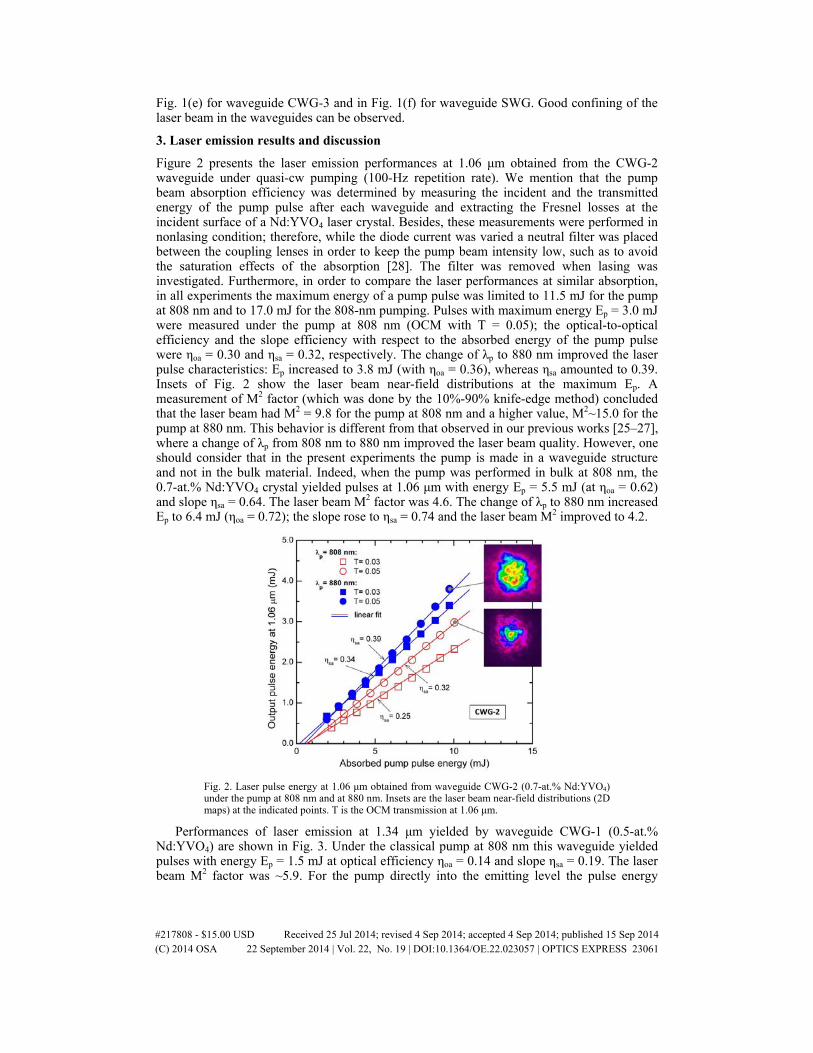
Fig. 1(e) for waveguide CWG-3 and in Fig. 1(f) for waveguide SWG. Good confining of the laser beam in the waveguides can be observed.
3. Laser emission results and discussion
Figure 2 presents the laser emission performances at 1.06 μm obtained from the CWG-2 waveguide under quasi-cw pumping (100-Hz repetition rate). We mention that the pump beam absorption efficiency was determined by measuring the incident and the transmitted energy of the pump pulse after each waveguide and extracting the Fresnel losses at the incident surface of a Nd:YVO4 laser crystal. Besides, these measurements were performed in nonlasing condition; therefore, while the diode current was varied a neutral filter was placed between the coupling lenses in order to keep the pump beam intensity low, such as to avoid the saturation effects of the absorption [28]. The filter was removed when lasing was investigated. Furthermore, in order to compare the laser performances at similar absorption, in all experiments the maximum energy of a pump pulse was limited to 11.5 mJ for the pump at 808 nm and to 17.0 mJ for the 808-nm pumping. Pulses with maximum energy Ep = 3.0 mJ were measured under the pump at 808 nm (OCM with T = 0.05); the optical-to-optical efficiency and the slope efficiency with respect to the absorbed energy of the pump pulse were ηoa = 0.30 and ηsa = 0.32, respectively. The change of λp to 880 nm improved the laser pulse characteristics: Ep increased to 3.8 mJ (with ηoa = 0.36), whereas ηsa amounted to 0.39. Insets of Fig. 2 show the laser beam near-field distributions at the maximum Ep. A measurement of M2 factor (which was done by the 10%-90% knife-edge method) concluded that the laser beam had M2 = 9.8 for the pump at 808 nm and a higher value, M2~15.0 for the pump at 880 nm. This behavior is different from that observed in our previous works [25–27], where a change of λp from 808 nm to 880 nm improved the laser beam quality. However, one should consider that in the present experiments the pump is made in a waveguide structure and not in the bulk material. Indeed, when the pump was performed in bulk at 808 nm, the 0.7-at.% Nd:YVO4 crystal yielded pulses at 1.06 μm with energy Ep = 5.5 mJ (at ηoa = 0.62) and slope ηsa = 0.64. The laser beam M2 factor was 4.6. The change of λp to 880 nm increased Ep to 6.4 mJ (ηoa = 0.72); the slope rose to ηsa = 0.74 and the laser beam M2 improved to 4.2.
Fig. 2. Laser pulse energy at 1.06 μm obtained from waveguide CWG-2 (0.7-at.% Nd:YVO4) under the pump at 808 nm and at 880 nm. Insets are the laser beam near-field distributions (2D maps) at the indicated points. T is the OCM transmission at 1.06 μm.
Performances of laser emission at 1.34 μm yielded by waveguide CWG-1 (0.5-at.% Nd:YVO4) are shown in Fig. 3. Under the classical pump at 808 nm this waveguide yielded pulses with energy Ep = 1.5 mJ at optical efficiency ηoa = 0.14 and slope ηsa = 0.19. The laser beam M2 factor was ~5.9. For the pump directly into the emitting level the pulse energy
#217808 - $15.00 USD Received 25 Jul 2014; revised 4 Sep 2014; accepted 4 Sep 2014; published 15 Sep 2014(C) 2014 OSA 22 September 2014 | Vol. 22, No. 19 | DOI:10.1364/OE.22.023057 | OPTICS EXPRESS 23061
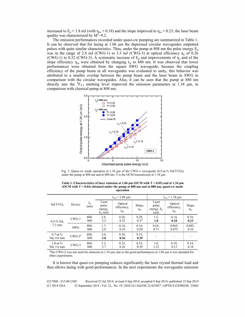
increased to Ep = 1.8 mJ (with ηoa = 0.18) and the slope improved to ηsa = 0.23; the laser beam quality was characterized by M2~9.2.
The emission performances recorded under quasi-cw pumping are summarized in Table 1. It can be observed that for lasing at 1.06 μm the depressed circular waveguides outputted pulses with quite similar characteristics. Thus, under the pump at 808 nm the pulse energy Ep was in the range of 2.8 mJ (CWG-1) to 3.3 mJ (CWG-3) at optical efficiency ηo of 0.26 (CWG-1) to 0.32 (CWG-3). A systematic increase of Ep and improvements of ηo and of the slope efficiency ηsa were obtained by changing λp to 880 nm. It was observed that lower performances were obtained from the square SWG waveguide; because the coupling efficiency of the pump beam in all waveguides was evaluated to unity, this behavior was attributed to a smaller overlap between the pump beam and the laser beam in SWG in comparison with the circular waveguides. Also, it can be seen that the pump at 880 nm directly into the 4F3/2 emitting level improved the emission parameters at 1.34 μm, in comparison with classical pump at 808 nm.
Fig. 3. Quasi-cw mode operation at 1.34 μm of the CWG-1 waveguide (0.5-at.% Nd:YVO4) under the pump at 808 nm and at 880 nm. T is the OCM transmission at 1.34 μm.
Table 1. Characteristics of laser emission at 1.06 μm (OCM with T = 0.05) and at 1.34 μm (OCM with T = 0.04) obtained under the pump at 808 nm and at 880 nm, quasi-cw mode
operation
Nd:YVO4 Device λp (nm)
λem = 1.06 μm λem = 1.34 μm Laserpulse
energy, Ep (mJ)
Optical efficiency,
ηoa
Slope, ηsa
Laserpulse
energy, Ep (mJ)
Optical efficiency,
ηoa
Slope, ηsa
0.5-% Nd, 7.2 mm
CWG-1 808, 880
2.8, 3.5
0.26, 0.32
0.29, 0.37
1.5, 1.8
0.14, 0.18
0.19, 0.23
SWG 808, 880
1.7, 2.0
0.14, 0.16
0.16, 0.20
0.65, 0.71
0.065, 0.075
0.085, 0.10
0.7-at.% Nd, 4.8 mm CWG-2a 808,
880 3.0, 3.8
0.30, 0.36
0.32, 0.39 - - -
1.0-at.% Nd, 3.6 mm CWG-3 808,
880 3.3, 3.7
0.32, 0.36
0.35, 0.39
1.0, 1.23
0.10, 0.13
0.14, 0.18
aThe CWG-2 was not used for emission at 1.34 μm; due to the good performances at 1.06 μm it was intended for other experiments.
It is known that quasi-cw pumping reduces significantly the laser crystal thermal load and thus allows lasing with good performances. In the next experiments the waveguides emission
#217808 - $15.00 USD Received 25 Jul 2014; revised 4 Sep 2014; accepted 4 Sep 2014; published 15 Sep 2014(C) 2014 OSA 22 September 2014 | Vol. 22, No. 19 | DOI:10.1364/OE.22.023057 | OPTICS EXPRESS 23062

characteristics were investigated in cw-pumping regime. For the pump at 880 nm the CWG-2 waveguide yielded 1.5-W output power (Pout) with efficiency ηoa = 0.27 (absorbed pump power, Pabs = 5.5 W); the slope efficiency was ηsa = 0.28 (as shown in Fig. 4). On the other hand, this waveguide delivered Pout = 0.9 W at 1.06 μm for Pabs = 5.2 W at 808 nm (ηoa~0.17); signs of power saturation were evident for Pabs in excess of 5.5 W at 808 nm, most probably due to stronger thermal effects induced in the waveguide at this wavelength λp. Table 2 summarizes the best results measured in cw mode operation at 1.06 μm from all the waveguides. Watt-level emission at 1.06 μm was available also from CWG-1 (Pout = 1.44 W) and CWG-3 (Pout = 1.21 W) under the pump at 880 nm. During these experiments the pump power at 808 nm and at 880 nm was limited to ~5.8 W and 8.0 W, respectively.
Fig. 4. Cw operation at 1.06 μm recorded from the CWG-2 waveguide, OCM with T = 0.05. The near-field distribution (2D plot) at the maximum output power is shown for the pump at 880 nm.
Table 2. Performances of cw laser emission at 1.06 μm, OCM with T = 0.05
Nd:YVO4 Waveguide λp (nm) Output power, Pout(W)
Opticalefficiency, ηoa
Slope, ηsa
0.5-at.% Nd, 7.2 mm
CWG-1 808, 880 1.25, 1.44 0.23, 0.28 0.25, 0.31 SWG 808, 880 0.54, 0.63 0.09, 0.11 0.10, 0.13
0.7-at.% Nd, 4.8 mm CWG-2 808, 880 0.9, 1.5 0.17, 0.27 0.20, 0.28
1.0-at.% Nd, 3.6 mm CWG-2 808, 880 1.13, 1.21 0.27, 0.30 0.30, 0.38
We mention that cw laser emission at 1.34 μm was obtained from all the circular waveguides, but of low level. For example, CWG-1 delivered Pout = 0.2 W for Pabs = 4.3 W at 880 nm; under similar Pabs at 808 nm the power Pout was limited to 0.15 W and showed time fluctuations. Increased thermal effects for the 1.34-μm emission in comparison with lasing at 1.06 μm are believed to be responsible for these results, like in the case of Nd:YAG [29, 30].
It is known that in the case of laser emission at 1.06 μm a change of λp from 808 nm to 880 nm increases the quantum defect ratio between the pump wavelength and the laser wavelength (ηqd = λp/λem) by ~8.8% (i.e. from ηqd~0.76 for λp = 808 nm to ηqd~0.827 for λp = 880 nm). In conditions of efficient emission this could induce a decrease of the generated heat from 0.24 (for λp = 808 nm) to ~0.173 (for λp = 880 nm), i.e. by ~28% [25, 26]. A proof of the heat generation reduction is the laser medium temperature under the two wavelengths of pumping. We comment that during the previous lasing experiments each laser crystal was wrapped in indium foil and placed in contact with a copper block. For the next measurements
#217808 - $15.00 USD Received 25 Jul 2014; revised 4 Sep 2014; accepted 4 Sep 2014; published 15 Sep 2014(C) 2014 OSA 22 September 2014 | Vol. 22, No. 19 | DOI:10.1364/OE.22.023057 | OPTICS EXPRESS 23063

the Nd:YVO4 upper cover (the indium foil and the copper) was removed and the crystal surface temperature was measured with a FLIR T620 thermal camera (−40°C to + 150°C range, ± 2°C accuracy). From these data the temperature of each Nd:YVO4 crystal surface positioned right above the waveguide was read. Although this is not the exact temperature in the waveguide (because the waveguide was positioned 500-μm below the crystal surface, and because of modified cooling conditions), the data suggest general behavior of the heat generated in the crystal under pumping at 808 nm and 880 nm, in lasing as well in the nonlasing conditions.
Fig. 5. Maximum temperature of the 0.7-at.% Nd:YVO4 crystal upper surface that was measured along the waveguide CWG-2 for an absorbed pump power of 5 W at (a) 808 nm and (b) 880 nm, nonlasing and lasing at 1.06 μm. Insets are the temperature maps of the laser crystal surface. The white dashed lines show the waveguide position.
Figure 5 shows the maximum temperature of the 0.7-at.% Nd:YVO4 upper surface for Pabs = 5.0 W at 808 nm (Fig. 5(a)) and at 880 nm (Fig. 5(b)). For the pump at 808 nm the temperature rose to ~128°C in nonlasing regime (this peak was obtained ~0.5 mm inside the waveguide, corresponding to the optimum focusing position of the pump beam). Once the lasing was allowed, the maximum temperature (Tmax) decreased to ~108°C (Fig. 5(a)); the laser output power was ~0.9 W (Fig. 4). On the other hand, under the pump at 880 nm and nonlasing Tmax was ~100°C; under lasing (with output power of ~1.3 W, Fig. 4) Tmax was reduced to ~90°C (Fig. 5(b)). It should be also noted that the temperature distributions are different, showing better uniformity under the pump at 880 nm; this is a consequence of a lower absorption coefficient at this pump wavelength in comparison with that at 808 nm. Similar behavior was observed for the other cladding waveguides. Evaluation of the temperatures corresponding to the exact experimental conditions can be performed from these data, a subject that will be considered in future. Other investigations could consider realizing of waveguides with decreased propagation losses, by improving the present writing techniques or by using the helical movement method [18]. It is also worthwhile to mention that the absorption efficiency was nearly 0.94 for the pump at 808 nm (for the waveguide CWG-1 that was inscribed in the 7.2-mm long, 0.5-at.% Nd:YVO4 crystal) and about 0.65 for the pump at 880 nm of the same waveguide; the design of waveguides with higher absorption at 880 nm will be also considered in further works.
4. Conclusions
In summary, we report on realization of depressed cladding waveguides in Nd:YVO4 by the direct writing technique with a fs-laser beam and have obtained laser emission from these waveguides under the pump with fiber-coupled diode lasers. Employing the classical pump at 808 nm (i.e. into the highly-absorbing 4F5/2 level), laser pulses at 1.06 μm with 3.0-mJ energy
#217808 - $15.00 USD Received 25 Jul 2014; revised 4 Sep 2014; accepted 4 Sep 2014; published 15 Sep 2014(C) 2014 OSA 22 September 2014 | Vol. 22, No. 19 | DOI:10.1364/OE.22.023057 | OPTICS EXPRESS 23064
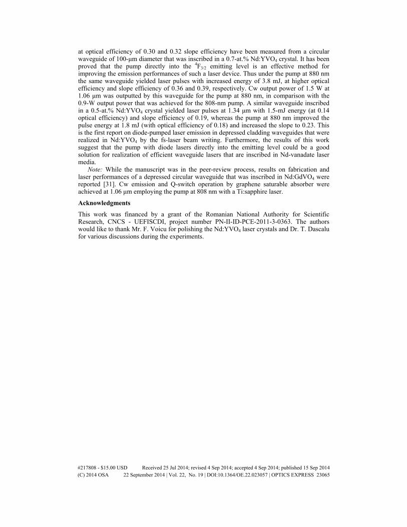
at optical efficiency of 0.30 and 0.32 slope efficiency have been measured from a circular waveguide of 100-μm diameter that was inscribed in a 0.7-at.% Nd:YVO4 crystal. It has been proved that the pump directly into the 4F3/2 emitting level is an effective method for improving the emission performances of such a laser device. Thus under the pump at 880 nm the same waveguide yielded laser pulses with increased energy of 3.8 mJ, at higher optical efficiency and slope efficiency of 0.36 and 0.39, respectively. Cw output power of 1.5 W at 1.06 μm was outputted by this waveguide for the pump at 880 nm, in comparison with the 0.9-W output power that was achieved for the 808-nm pump. A similar waveguide inscribed in a 0.5-at.% Nd:YVO4 crystal yielded laser pulses at 1.34 μm with 1.5-mJ energy (at 0.14 optical efficiency) and slope efficiency of 0.19, whereas the pump at 880 nm improved the pulse energy at 1.8 mJ (with optical efficiency of 0.18) and increased the slope to 0.23. This is the first report on diode-pumped laser emission in depressed cladding waveguides that were realized in Nd:YVO4 by the fs-laser beam writing. Furthermore, the results of this work suggest that the pump with diode lasers directly into the emitting level could be a good solution for realization of efficient waveguide lasers that are inscribed in Nd-vanadate laser media.
Note: While the manuscript was in the peer-review process, results on fabrication and laser performances of a depressed circular waveguide that was inscribed in Nd:GdVO4 were reported [31]. Cw emission and Q-switch operation by graphene saturable absorber were achieved at 1.06 μm employing the pump at 808 nm with a Ti:sapphire laser.
Acknowledgments
This work was financed by a grant of the Romanian National Authority for Scientific Research, CNCS - UEFISCDI, project number PN-II-ID-PCE-2011-3-0363. The authors would like to thank Mr. F. Voicu for polishing the Nd:YVO4 laser crystals and Dr. T. Dascalu for various discussions during the experiments.
#217808 - $15.00 USD Received 25 Jul 2014; revised 4 Sep 2014; accepted 4 Sep 2014; published 15 Sep 2014(C) 2014 OSA 22 September 2014 | Vol. 22, No. 19 | DOI:10.1364/OE.22.023057 | OPTICS EXPRESS 23065

2014PHOTONICSEUROPE•
Technical Programme
Exhibition Guide
SQUARE Brussels Meeting CentreBrussels, Belgium
Exhibition: 15–16 April 2014Conferences: 14–17 April 2014
www.spie.org/pe
EPE14 Final Front#7.indd iEPE14 Final Front#7.indd i 3/24/14 4:07 PM3/24/14 4:07 PM
Laser Emission from Diode-Pumped Nd:YAG Cladding Waveguides Obtained by Direct Writing with a
Femtosecond-Laser Beam
Gabriela SALAMU*a,c, Flavius VOICUa,c, Florin JIPAb,c, Marian ZAMFIRESCUb, Traian DASCALUa, Nicolaie PAVEL**,a
aNational Institute for Laser, Plasma and Radiation Physics, Laboratory of Solid-State Quantum Electronics, Bucharest R-077125, Romania; bNational Institute for Laser, Plasma and Radiation
Physics, Laser Department, Solid-State Laser Laboratory, Bucharest R-077125, Romania; cDoctoral School of Physics, University of Bucharest, Romania
ABSTRACT
Cladding waveguides have been realized in Nd:YAG by direct writing with a femtosecond-laser beam. A classical method that inscribes many tracks around the waveguide circumference with step-by-step translations of the laser medium, and a new technique in which the laser medium is moved on a helical trajectory and that delivers waveguides with well-defined walls were employed. Laser emission on the 1.06 μm 4F3/2→4I11/2 transition and at 1.3 μm on the 4F3/2→4I13/2 line was obtained under the pump with a fiber-coupled diode laser. Thus, laser pulses at 1.06 μm with energy of 1.3 mJ for the pump at 807 nm with pulses of 12.5-mJ energy were recorded from a circular waveguide of 100-μm diameter that was inscribed in a 5-mm long, 0.7-at.% Nd:YAG single crystal by the classical translation technique. A similar waveguide that was realized in a 5-mm long, 1.1-at.% Nd:YAG ceramic increased the 1.06-μm laser pulse energy to 2.15 mJ for the pump pulses of 13.1-mJ energy. Furthermore, a circular waveguide of 100-μm diameter that was inscribed in the Nd:YAG ceramic by the helical-movement method yielded pulses at 1.06 μm with increased maximum energy of 3.2 mJ; the overall optical-to-optical efficiency was 0.24, and the laser operated with a slope efficiency of 0.29. The same device outputted laser pulses at 1.3 μm with energy of 1.15 mJ.
Keywords: Lasers, solid-state; Lasers, neodymium; Diode-pumped lasers; Optical waveguides; Micro-optical devices.
1. INTRODUCTION
The waveguide lasers are of interest in optoelectronics due to their compact dimensions, still yielding moderate or similar output performances in comparison with the bulk material [1]. This kind of optical devices can be fabricated in an existing host by different techniques, such as thermal ion in-diffusion of active rare-earth in ferroelectrics [2], ion or proton exchange [3, 4], or proton or ion beam implantation [5, 6]; proton writing is an advanced, single-pass writing method that delivers buried waveguides at a defined depth within the bulk material without using a mask on the substrate [7, 8]. On the other hand, nowadays the optical writing is recognized as a powerful and efficient technique for realizing waveguides in many transparent optical materials. This approach uses a femtosecond (fs)-laser beam with suitable wavelength, energy and temporal properties to modify locally the medium refractive index [9]. Depending also of the material type, the change of the refractive index in the irradiated zone could be either positive or negative. Thus, in many glasses, as well as in LiNbO3, the irradiated part of material melts during the writing process and then it re-solidifies. The affected volume contracts and finally a track with a higher refractive index in comparison with that of the bulk medium is obtained; this track (or line) is used itself for light propagation [10-12].
Manufacturing of a laser waveguide in a crystal is more challenging. In comparison with glasses a different approach is used, by which regions (or boundaries) of low refractive index (that act as barriers) are realized around a crystal volume (that can be modified, or not) where the waveguide is intended to be obtained. In some cases the inscribing process induces severe changes or can even damage the crystal inside the track; a lower refractive index in comparison with that of the bulk is obtained in the irradiated line. Furthermore, an increased refractive index results in the adjacent regions by *[email protected]; **[email protected]: phone/fax +40 21 457-4489; ecs.inflpr.ro
Laser Sources and Applications II, edited by Jacob I. Mackenzie, Helena JelÍnková, Takunori Taira, Marwan Abdou Ahmed,Proc. of SPIE Vol. 9135, 91351F · © 2014 SPIE · CCC code: 0277-786X/14/$18 · doi: 10.1117/12.2052250
Proc. of SPIE Vol. 9135 91351F-1
Downloaded From: http://proceedings.spiedigitallibrary.org/ on 05/29/2014 Terms of Use: http://spiedl.org/terms
stress-induced field. The laser waveguide may be located in the vicinity of such a track, above or below the track tips, in a small region with the increased refraction index [13]. This kind of waveguide yield laser emission of low performances and therefore is quite rare. The most employed arrangement consists of two tracks: For a separation of few μm to few tens of μm the refractive index contrast between the lines is increased, this region being used as the waveguide core. Linear, two-wall type waveguides were obtained in many laser media, like Nd:Y3Al5O12 (Nd:YAG) [14-16], Yb:YAG [17, 18], or Nd:YVO4 [19-21], Nd:GdVO4 [22] and Nd:LuVO4 [23], Yb-doped monoclinic potassium double tungstates, Yb:KGd(WO4)2 and Yb:KY(WO4)2 [24], or Pr:SrAl12O19 [25] and Pr:YLiF4 (Pr:YLF) [26]. Curved two-wall type waveguides were inscribed recently in Yb:YAG [27]. Laser emission was obtained from these waveguides using mainly the pump with tunable Ti:sapphire lasers, whereas the pump with diode lasers was considered in few papers [18, 24, 25].
The demonstration of the first depressed-cladding waveguide in Nd:YAG [28] was a significant step toward further size reduction of a waveguide laser, which should also include the pump source that usually is an array or a fiber-coupled diode laser. Using this fs-laser writing technique many tracks are inscribed around the contour of a defined material volume, i.e. of the waveguide core. There is no damage of the irradiated material (inside the track); furthermore, the change of the refractive index averaged on the cross-section of a track is negative [29, 30]. Tubular waveguides were written in Nd:YAG single crystals [28-30] and Nd:YAG ceramic media [31], in Cr4+:YAG saturable absorber crystal for Q-switch operation [32], in Tm:YAG [33], Nd:YVO4 [34] or Pr:YLF [26], or in Nd:LGS [35] and ZnS [36]. Moreover, circular double-cladding waveguides were realized in Nd:YAG [37, 38]. Laser emission under the pump with diode lasers has been reported in some papers [26, 28-30], but still the pump with Ti:sapphire laser was principal.
Recently we have reported realization of two-wall type waveguides and of cladding waveguides with elliptical, circular and rectangular shapes in Nd:YAG single crystal, from which laser emission at 1.06 μm and at 1.3 μm was obtained under the pump with a fiber-coupled diode laser [39, 40]. Furthermore, laser emission at 946 nm was observed from a large-core elliptical waveguide that was written in a 0.7-at.% Nd:YAG single crystal. The investigations were extended to Nd:YAG ceramics of various doping level, and efficient laser emission was recorded from circular waveguides with up to 100-μm diameter [41]. In this work we are presenting additional results on emission at 1.06 μm and at 1.3 μm from cladding waveguides that were inscribed in Nd:YAG single crystal and ceramic media by the classical step-by-step translation method [28]. Furthermore, we are applying for the first time a new writing scheme, in which the laser medium is moved on a helical trajectory [42], to obtain circular cladding waveguides with well defined walls. Efficient laser emission is demonstrated from these novel waveguides under the pump with a fiber-coupled diode laser.
2. EXPERIMENTAL CONDITIONS. RESULTS AND DISCUSSION
2.1 The writing techniques
In order to write tracks in Nd:YAG we used two experimental arrangements, as shown in Fig. 1. The fs-laser pulses were delivered by a chirped pulsed amplified system (CLARK CPA-2101). This laser emitted pulses at 775 nm with energy up to 0.6 mJ; the pulse repetition rate and duration were 2 kHz and 200 fs, respectively. The beam was linear polarized and its transverse distribution was characterized by an M2 factor of 1.5. An optical attenuator that consisted of a combination of half-wave plate, a polarizer and various calibrated neutral filters was used to control the fs-laser pulse energy. An optical system (which was either an objective microscope or a single aspherical lens) was employed to focus the fs-laser beam into the laser medium.
The step-by-step translation technique [28] is illustrated in Fig. 1a. In this scheme the Nd:YAG medium is moved transversally to the fs-laser beam, on the Oy direction starting from surface S1 (or S2). The fs-laser beam focusing point is moved to a new location (in the Oxz plane) once the Nd:YAG opposite surface S2 (or S1) is reached, and the writing process continues with a new translation along Oy. Thus, an unmodified volume of Nd:YAG (i.e. the waveguide core) that is surrounded by many tracks with a decreased refractive index and that acts as the waveguide wall is obtained. During the writing process care is paid to avoid the overlap between the fs-laser beam and any of the already inscribed tracks. On the other hand, the tracks are inscribed at a certain distance between (typical of few μm), in order to avert possible fracture of the medium. Therefore, with this writing technique an unmodified (or little modified) region will remain between each consecutive tracks. These zones with unchanged (or little changed) refractive index can increase the waveguide propagation losses, thus influencing the laser emission performances.
The idea of helical movement of the laser medium during the inscribing process is illustrated in Fig. 1b. Thus, the Nd:YAG is 90o rotated on the motorized mechanical stage; the medium is moved circularly in the Oxz plane and it is translated along direction Oy (from surface S1 to surface S2). This direction is parallel to the medium axis on which
Proc. of SPIE Vol. 9135 91351F-2
Downloaded From: http://proceedings.spiedigitallibrary.org/ on 05/29/2014 Terms of Use: http://spiedl.org/terms

Clark CPA -2101Femtosecond (Is) Laser J
Optical
45°HRM
Nd:YAG
Opticalsystem, 02
a) b)
L
d)
CW
G-3
lineartracks
4)=100 µm
laser emission will be obtained (and not perpendicular, like in the case of the step-by-step translation method). However, it should be mentioned that the waveguide length ( l ) is limited by the characteristics (focal length and the confocal parameter) of the optical system used to focus the fs-laser beam, and good care should be taken in order to inscribe waveguides long enough for efficient absorption of the pump beam. As it was already mentioned, the helical movement of the medium was used recently to obtain waveguides in As 2 S 3 glass, the track having a length of 25 mm and radius below 10 μ m [42]. Then, specific to many glasses, this track was used itself for light waveguiding. Therefore, in this work we report on the first attempt of realizing wave guides in a laser medium with a helical movement [43].
Fig. 1 The experimental setup employed for inscribing claddi ng waveguides in Nd:YAG by direct writing with a fs-laser beam and using a) a classical step-by-step translation scheme and b) a helical movement of the laser medium is shown.
After the writing, both sides (S1 and S2) of a Nd:YAG medium were polished; this process reduced each medium initial length by few hundreds of μ m. The propagation losses of a waveguide were evaluated by coupling (with an efficiency evaluated to unity) a polarized HeNe laser beam into every structure, and by measuring the power of the transmitted light. During laser experiments the Nd:YAG media were placed on a metallic plat e, without any cooling.
2.2 Waveguides inscribed by the classical translation technique
The first waveguides were inscribed in a 0.7-at.% Nd:YAG single crystal [39]; the initial medium length, l = 5.4 mm, was shortened to ~5.0 mm after polishing. A 20 × magnification microscope (numerical aperture NA= 0.40) was used to focus the fs-laser beam to a spot of ~7.0- μ m diameter (in air). The fs-laser pulse energy was set at 3.9 μ J. The tracks were written with a translation stage speed of 50 μ m/s.
Fig. 2 Microscope images of three cladding waveguides (CWG) inscribed in a 0.7- at.% Nd:YAG single crystal: a) CWG-1, elliptical with core of 120 μ m × 165 μ m size; b) CWG-2, circular with a diameter φ = 80 μ m, and in a 0.7-at.% Nd:YAG ceramic: c) CWG-3, circular with a diameter φ = 100 μ m are presented. d) Top view of CWG-3 shows its circumference that consists of linear, parallel tracks.
Optical images of two cladding waveguides that were inscribe d in the 0.7-at.% Nd:YAG sing le crystal are presented in Fig. 2. The first one was elliptical with cross section of 120 μ m × 165 μ m size and consisted of parallel tracks that were written 10- μ m apart; as shown in Fig. 2a this waveguide will be denoted by CWG-1. The second waveguide (presented in Fig. 2b by CWG-2) had a near ly-circular core with a diameter φ = 80 μ m. Both waveguides were centered at a depth of
Proc. of SPIE Vol. 9135 91351F-3
Downloaded From: http://proceedings.spiedigitallibrary.org/ on 05/29/2014 Terms of Use: http://spiedl.org/terms

CYL1 L2
a)
HRM OCM
1.5
U)col6J
0.5
0.00 5 10
Pump pulse energy, E0 (mJ)15
250 μ m under Nd:YAG surface that faced the microscope objectiv e. One could observe that the tracks fingerprints are quite long, and almost every one is followed by a short add itional mark; these artifacts are believed to result from a too high energy of the fs-laser beam and due to the focusing optics characteristics. Therefore, new waveguides were written in an available, 5.0-mm long, 0.7-at.% Nd:YAG ceramic medium (Baikowski Co., Ltd., Japan). This time the fs-laser beam was focused to a diam eter (in air) of ~5.0 μ m by a 7.5-mm focal length achromatic lens (NA= 0.3). The fs-laser pulse energy was set at ~1.0 μ J, and the distance between two parallel tracks was reduced at 5 to 6 μ m. A circular waveguide with φ = 100 μ m that was inscribed in the Nd:YAG ceramic is shown in Fig. 2c; it will be denoted by CWG-3. Furthermore, a top view of this structure is given in Fig. 2d: It shows clearly the linear, parallel inscribed tracks that together build the waveguide walls of decreased refractive index. The propagation losses were evaluated to 1.4 dB/cm for CWG-1, to 1.6 dB/cm for CWG-2 and to about 1.35 dB/cm for the CWG-3 waveguide.
For the laser emission experiments at 1.06 μ m ( λ em ) we built an experimental set-up, as shown in Fig. 3a. The resonator was linear, with the mirrors placed very close of the Nd :YAG surfaces. The rear high-reflectivity mirror (HRM) was plane, being coated HR (R> 0.998) at 1.06 μ m and with high transmission, HT (T> 0.98) at the pump wavelength ( λ p ) of 807 nm. The output coupling mirror (OCM) was also flat, with a defined transmission, T at 1.06 μ m. The pump was made with a fiber-coupled diode laser (LIMO Co., Germany) that was operated in quasi-cw mode (pump pulse duration of 1 ms and 10-Hz repetition rate). The fiber end (100- μ m diameter, NA= 0.22) was imaged into Nd:YAG using an achromatic collimating lens of 50-mm focal length and an achromatic focusing lens of 30-mm focal length.
Fig. 3 a) The experimental set-up used for laser emission at 1.06 μ m. L1, L2: lenses; HRM: high-reflectivity mirror; OCM: out-coupling mirror. b) Laser pulse energy at 1.06 μ m versus pump-pulse energy, emission from the waveguides inscribed by classical tran slation technique in the 5. 0-mm thick, 0.7-at.% Nd:YAG media; OCM with T= 0.10.
The laser pulse energy (E p ) at λ em = 1.06 μ m versus pump pulse energy (E pump ) at 807 nm is shown in Fig. 3b. The best performances were measured with an OCM of transmission T= 0.10 (at 1.06 μ m). Thus, the elliptical CWG-1 waveguide yielded pulses with energy E p = 0.8 mJ for E pump = ~9.1 mJ; this corresponds to an ov erall optical-to-optical efficiency η o ~0.9. The slope efficiency was η s = 0.15. Using the same pumping conditions (in these first experiments E pump was limited at 9.1 mJ due to some technical reasons), the circular CWG-2 waveguide delivered laser pulses with E p = 0.7 mJ (at η o ~ 0.8) and slope η s = 0.14. In comparison, the circular CWG-3 waveguide showed a slightly decreased threshold of emission (3.3 mJ versus 3.9 mJ for CWG-1 and 4.3 mJ for CWG-2), and outputted similar energy of E p = 0.82 mJ for E pump = 9.5 mJ. Pulses with energy up to E pump = 12.5 mJ could be inserted in this waveguide. Consequently, the laser pump energy increased to E p = 1.3 mJ (at η o = 0.10), while the slope efficiency limited at η s = 0.14.
2.3 Waveguides realized by the helical movement of the medium
In the writing experiments by the helical moving of the laser medium we used a 5.0-mm thick, 1.1-at.% Nd:YAG ceramic (Baikowski Co., Ltd., Japan). Th e fs-laser beam was focused to ~12- μ m diameter (in air) with a 10 × microscope objective (NA= 0.30); the pulse energy was set at a slightly high value of 15 μ J. In addition, a video camera was employed to visualize the writing process; in this way the speed of rotation (in the Oxz plane, Fig. 1b) and the translation velocity (on Oy direction) were chosen properly, for a complete overlap between the traces inscribed at each helix.
Proc. of SPIE Vol. 9135 91351F-4
Downloaded From: http://proceedings.spiedigitallibrary.org/ on 05/29/2014 Terms of Use: http://spiedl.org/terms
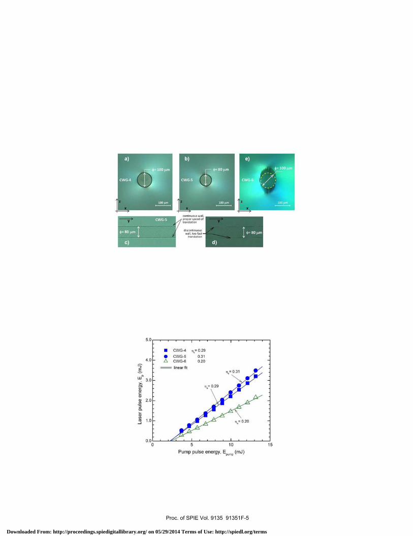
11
b)
CWG-5
continuous wall,proper speed oftranslation Y
100 F
discontinuouswall, too fast
translation
5.0
4.0
E
wn 3.0
4)C0)
N 2.0f/)
5 10
Pump pulse energy, EPmp
(mJ)
15
Two circular waveguides are presented in Fig. 4. The first one, shown in Fig. 4a by CWG-4, has a diameter φ = 100 μ m. In the case of this waveguide a complete circle in the Ox z plane was inscribed in 0.84 sec, and the time necessary for writing completely the waveguide was about 2 min. A waveguide with a diameter φ = 80 μ m (CWG-5) is shown in Fig. 4b. In addition, Fig. 4c illustrates clearly that waveguides with continuous, well defined walls can be obtained by a correct correlation between the rotation and the translation speed. A too-fast translation of the medium along the helix axis could deliver a structure with discontinuous walls, as shown in Fig. 4d. For comparison, another waveguide with diameter φ = 100 μ m was inscribed in the same Nd:YAG ceramic by th e step-by-step translatio n method. The fs-laser beam was set at 1.5 μ J and an achromatic lens of 7.5 μ m focal length was used for focusing. This waveguide (denoted by CWG-6) is shown in Fig. 4e. The structure was centered 500- μ m bellow the Nd:YAG surface an d consisted of 38 tracks that were inscribed on Oy direction (like in Fig. 1a) at 50- μ m/s speed of the translation st age. In this case, the time necessary for writing the waveguide was about 1 h. Therefore, helical movement of the medium requires a much shorter time for the inscribing process, in comparison with the classical step-by-step translation method.
Fig. 4 Microscope images of two circular waveguides inscri bed in a 1.1-at.% Nd:YAG cer amic by heli cal movement: a) CWG-4, with a diameter φ = 100 μ m and b) CWG-5, with φ = 80 μ m. Top view of CWG-5 showing c) the continuous, well-defined walls, but also d) a case of discontinuous walls, when helical movement was done with too much speed of translation. Classical translation technique was used to write a circular waveguide: e) CWG-6, with φ = 100 μ m.
The propagation losses at 632.8 nm were 1.1 dB/cm for the CWG-4 waveguide and ~1.2 dB/cm for CWG-5. Differences between losses depending of the HeNe laser beam polarizati on were not apparent for these waveguides. On the other hand, losses of the CWG-6 waveguide amounted to 1.6 dB/cm for TM polarization of the HeNe beam (i.e. parallel to the Oz inscribing axis, Fig. 4e), and were higher, of ~1.9 dB/cm, for the TE polarized HeNe beam. It is considered that leakage of the TE polarized light through the zones of unmodifi ed material could be a reason for these increased losses.
Fig. 5 Energy of the laser pulses at 1.06 μ m yielded by the cladding waveguides that were inscribed in the 5-mm thick, 1.1-at.% Nd:YAG ceramic; OCM with T= 0.10.
Proc. of SPIE Vol. 9135 91351F-5
Downloaded From: http://proceedings.spiedigitallibrary.org/ on 05/29/2014 Terms of Use: http://spiedl.org/terms
The laser pulse energy Ep at 1.06 μm is shown in Fig. 5 versus Epump for and OCM with T= 0.10. The 100-μm diameter CWG-4 waveguide delivered laser pulses with Ep= 3.2 mJ for Epump= 13.1 mJ (corresponding to ηo= 0.24); the slope efficiency amounted at ηs= 0.29. The CWG-5 waveguide outputted a little high energy Ep= 3.5 mJ (with ηo= 0.265) at an improved slope efficiency ηs= 0.31. The pump-beam coupling efficiency was estimated close to unity for both waveguides, while the propagation losses are similar. Therefore, the higher performances recorded from the CWG-5 waveguide were attributed to a better overlap between the laser beam and the pump beam, in comparison with that of the CWG-4 waveguide. On the other hand, the best characteristics measured from the CWG-6 waveguide were Ep= 2.15 mJ (with ηo= 0.16) and slope ηs= 0.20.
Table 1. The main results for pulsed laser emission at 1.06 μm and 1.3 μm recorded from cladding waveguides that were inscribed in 5.0-mm long Nd:YAG media are summarized. 0.7-at.% Nd:YAG single crystal: CWG-1 (elliptical, 120 μm × 165 μm); CWG-2 (diameter φ= 80 μm); CWG-3 (φ= 100 μm). 1.1-at.% Nd:YAG ceramic: CWG-4 (φ= 100 μm); CWG-5 (φ= 80 μm); CWG-6 (φ= 100 μm).
Nd:YAG The
cladding waveguide
Writing technique
λem= 1.06 μm (OCM with T= 0.10)
λem= 1.3 μm (OCM with T= 0.03)
Laser pulse energy, Ep (mJ)
Optical efficiency,
ηo
Slope efficiency,
ηs
Laser pulse energy, Ep (mJ)
Optical efficiency,
ηo
Slope efficiency,
ηs
0.7-at.% Nd, single crystal
CWG-1 CWG-2 CWG-3
Translation 0.8 0.7 1.3
0.09 0.08 0.10
0.15 0.14 0.14
0.3 0.25 0.4
0.03 ~0.03 0.03
0.07 0.06 0.06
1.1-at.% Nd, ceramic
CWG-4 CWG-5
Helical movement
3.2 3.5
0.24 0.26
0.29 0.31
1.15 0.95
0.09 0.07
0.12 0.11
CWG-6 Translation 2.15 0.16 0.20 0.92 0.07 0.10
The main results reported in this work are summarized in Table 1. For the emission at λem= 1.3 μm a similar resonator to that shown in Fig. 3a was used. The mirror HRM was coated HR at 1.3 μm and HT at 807 nm; the OCM had a defined T at 1.3 μm, but it was also coated HT (T> 0.995) at 1.06 μm in order to suppress emission at this high-gain wavelength. With an OCM of T= 0.03 at 1.3 μm the CWG-4 waveguide (that was inscribed in the 1.1-at.% Nd:YAG ceramic by the helical moving of the medium) yielded laser pulses with Ep= 1.15 mJ at optical efficiency ηo~0.9; the slope of efficiency was ηs= 0.12. Laser pulses at 1.3 μm with Ep= 0.4 mJ were obtained from the 100-μm diameter CWG-3 waveguide that was written in the 0.7-at.% Nd:YAG single crystal by the step-by-step translation technique. In a final experiment the pump was made in cw mode with the same fiber-coupled diode laser. Output power of 0.48 W power at 1.06 μm was recorded from the CWG-4 waveguide for the pump with 3.7 W power (and an OCM with T= 0.05 at 1.06 μm); the slope was ηs= 0.24. The output power at 1.3 μm was much lower, ~0.15 W, under similar pump conditions.
3. CONCLUSIONS
In conclusion, we report on realization of cladding waveguides in Nd:YAG by direct inscribing with a fs-laser beam. A classical method in which the laser medium is step-by-step translated perpendicular to the writing direction, and a new method that uses a helical moving of the Nd:YAG medium parallel to the fs-laser beam are used. It is shown that helical movement technique allows realization of cladding waveguides with well defined walls and decreased propagation losses in comparison with the waveguides obtained by the classical inscribing method. Laser pulses with energy of 3.2 mJ at 1.06 μm and with 1.15-mJ energy at 1.3 μm were obtained from an 100-μm diameter circular waveguide that was written in a 5-mm long, 1.1-at.% Nd:YAG ceramic by the helical movement scheme. A similar waveguide that was inscribed in the same Nd:YAG ceramic yielded laser pulses with 2.15 mJ energy at 1.06 μm and with 0.92-mJ energy at 1.3 μm. The helical movement method needs a much shorter time than the classical approach in order to inscribe similar waveguides. On the other hand, the new method requires careful selection of the focusing optic for realizing a long waveguide, with adequate length for high absorption of the pump beam and efficient laser operation. The new method of helical movement of the medium could be a step forward toward realization of integrated diode-pumped lasers consisting of cladding waveguides inscribed by direct optical writing with an fs-laser beam.
Proc. of SPIE Vol. 9135 91351F-6
Downloaded From: http://proceedings.spiedigitallibrary.org/ on 05/29/2014 Terms of Use: http://spiedl.org/terms
ACKNOWLEDGEMENTS
This work was supported by the Romanian National Authority for Scientific Research, CNDI-UEFISCDI, project IDEI 36/2011 (PN-II-ID-PCE-2011-3-0363).
REFERENCES
[1] Grivas, C., “Optically pumped planar waveguide lasers, Part I: Fundamentals and fabrication techniques,” Progress in Quantum Electron. 35, 159-239 (2011).
[2] Becker, C., Oesselke, T., Pandavenes, J., Ricken, R., Rochhausen, K., Schreiber, G., Sohler, W., Suche, H., Wessel, R., Balsamo, S., Montrosset, I., and Sciancalepore., D, “Advanced Ti:Er:LiNbO3 waveguide lasers,” IEEE J. Sel. Top. Quantum Electron. 33, 101-113 (1997).
[3] Izawa, T., and Nakagome, H., “Optical waveguide formed by electrically induced migration of ions in glass plates,”Appl. Phys. Lett. 21, 584-586 (1971).
[4] Jackel, J. L., Rice, C. E., and Veselka, J. J., “Proton exchange for high-index waveguides in LiNbO3,” Appl. Phys. Lett. 41, 607-608 (1982).
[5] Polman, A., “Erbium implanted thin film photonic materials,” J. Appl. Phys. 82, 1-39 (1997). [6] Chen, F., Tan, Y., and Jaque, D., “Ion-implanted optical channel waveguides in neodymium-doped yttrium
aluminum garnet transparent ceramics for integrated laser generation,” Opt. Lett. 34, 28-30 (2009). [7] Watt, F., Breese, M. B. H., Bettiol, A. A., and van Kan, J. A., “Proton beam writing,” Mater. Today 10, 20-29
(2007). [8] Yao, Y., Tan, Y., Dong, B., Chen, F., and Bettiol, A. A., “Continuous wave Nd:YAG channel waveguide laser
produced by focused proton beam writing,” Opt. Express 18, 24516-24521 (2010). [9] Davis, K. M., Miura, K., Sugimoto, N., and Hirao, K., “Writing waveguides in glass with a femtosecond laser,”
Opt. Lett. 21, 1729-1731 (1996). [10] Della Valle, G., Taccheo, S., Osellame, R., Festa, A., Cerullo, G., and Laporta, P.,” 1.5 μm single longitudinal
mode waveguide laser fabricated by femtosecond laser writing,“ Opt. Express 15, 3190-3194 (2007). [11] Marshall, G. D., Dekker, P., Ams, M., Piper, J.A., and Withford, M. J., “Directly written monolithic waveguide
laser incorporating a distributed feedback waveguide-Bragg grating,” Opt. Lett. 33, 956-958 (2008). [12] Mary, R., Beecher, S. J., Brown, G., Thomson, R. R., Jaque, D., Ohara, S., and Kar, A. K., “Compact, highly
efficient ytterbium doped bismuthate glass waveguide laser,” Opt. Lett. 37, 1691-1693 (2012). [13] Apostolopoulos, V., Laversenne, L., Colomb, T., Depeursinge, C., Salathé, R. P., and Pollnau, M., “Femtosecond-
irradiation-induced refractive-index changes and channel waveguiding in bulk Ti3+:Sapphire,” Appl. Phys. Lett., 85, 1122-1124 (2004).
[14] Torchia, G. A., Rodenas, A., Benayas, A., Cantelar, E., Roso, L., and Jaque, D., “Highly efficient laser action in femtosecond-written Nd:yttrium aluminum garnet ceramic waveguides,” Appl. Phys. Lett. 92, 111103 (2008).
[15] Siebenmorgen, J., Petermann, K., Huber, G., Rademaker, K., Nolte, S., and Tünnermann, A., “Femtosecond laser written stress-induce Nd:Y3Al5O12 (Nd:YAG) channel waveguide laser,“ Appl. Phys. B 97, 251-255 (2009).
[16] Calmano, T, Siebenmorgen, J., Hellmig, O., Petermann, K., and Huber, G., “Nd:YAG waveguide laser with 1.3 W output power, fabricated by direct femtosecond laser writing,“ Appl. Phys. B 100, 131-135 (2010).
[17] Siebenmorgen, J., Calmano, T., Petermann, K, and Huber, G., “Highly efficient Yb:YAG channel waveguide laser written with a femtosecond-laser,“ Opt. Express 18, 16035-16041 (2010).
[18] Calmano, T., Siebenmorgen, J., Paschke, A.-G., Fiebig, C., Paschke, K., Erbert, G., Petermann, K., and Huber, G., “Diode pumped high power operation of a femtosecond laser inscribed Yb:YAG waveguide laser,” Opt. Mater. Express 1, 428-433 (2011).
[19] Tan, Y., Chen, F., Vázquez de Aldana, J. R., Torchia, G. A., Benayas, A., and Jaque, D., “Continuous wave laser generation at 1064 nm in femtosecond laser inscribed Nd:YVO4 channel waveguides,” Appl. Phys. Lett. 97, 031119 (2010).
[20] Tan, Y., Jia, Y., Chen, F., Vázquez de Aldana, J. R., and Jaque, D., “Simultaneous dual-wavelength lasers at 1064 and 1342 nm in femtosecond-laser-written Nd:YVO4 channel waveguides,” J. Opt. Soc. Am. B 28, 1607-1610 (2011).
Proc. of SPIE Vol. 9135 91351F-7
Downloaded From: http://proceedings.spiedigitallibrary.org/ on 05/29/2014 Terms of Use: http://spiedl.org/terms

[21] Dong, N., Tan, Y., Benayas, A., Vázquez de Aldana, J., Jaque, D., Romero, C., Chen, F., and Lu, Q., “Femtosecond laser writing of multifunctional optical waveguides in a Nd:YVO4-KTP hybrid system,” Opt. Lett. 36, 975-977 (2011).
[22] Tan, Y., Rodenas, A., Chen, F., Thomson, R. R., Kar, A. K., Jaque, D., and Lu, Q. M., “70% slope efficiency from an ultrafast laser-written Nd:GdVO4 channel waveguide laser,” Opt. Express 18, 24994-24999 (2010).
[23] Ren, Y., Dong, N., Macdonald, J., Chen, F., Zhang, H., and Kar, A. K., “Continuous wave channel waveguide lasers in Nd:LuVO4 fabricated by direct femtosecond laser writing,” Opt. Express 20, 1969-1974 (2012).
[24] Bain, F. M., Lagatsky, A. A., Thomson, R. R., Psaila, N. D., Kuleshov, N. V., Kar, A. K., Sibbett, W., and Brown, C. T. A., “Ultrafast laser inscribed Yb:KGd(WO4)2 and Yb:KY(WO4)2 channel waveguide lasers,” Opt. Express 17, 22417-22422 (2009).
[25] Calmano, T., Siebenmorgen, J., Reichert, F., Fechner, M., Paschke, A.-G., Hansen, N.-O., Petermann, K., and Huber, G., “Crystalline Pr:SrAl12O19 waveguide laser in the visible spectral region,“ Opt. Lett. 36, 4620-4622 (2011).
[26] Müller, S., Calmano, T., Metz, P., Hansen, N.-O., Kränkel, C., and Huber, G., “Femtosecond-laser-written diode-pumped Pr:LiYF4 waveguide laser,“ Opt. Lett. 37, 5223-5225 (2012).
[27] Calmano, T., Paschke, A.-G., Müller, S., Kränkel, C., and Huber, G., “Curved Yb:YAG waveguide lasers, fabricated by femtosecond laser inscription,“ Opt. Express 21, 25501-25508 (2013).
[28] Okhrimchuk, A. G., Shestakov, A. V., Khrushchev, I., and Mitchell, J., “Depressed cladding, buried waveguide laser formed in a YAG:Nd3+ crystal by femtosecond laser writing,” Opt. Lett. 30, 2248-2250 (2005).
[29] Okhrimchuk, A., “Femtosecond Fabrication of Waveguides,” in [Ion-Doped Laser Crystals, Coherence and Ultrashort Pulse Laser Emission], Dr. F. J. Duarte (Ed.), InTech, DOI: 10.5772/12885, 519-542 (2010).
[30] Okhrimchuk, A., Mezentsev, V., Shestakov, A., and Bennion, I., “Low loss depressed cladding waveguide inscribed in YAG:Nd single crystal by femtosecond laser pulses,” Opt. Express 20, 3832-3843 (2012).
[31] Liu, H., Jia, Y., Vázquez de Aldana, J. R., Jaque, D., and Chen, F., “Femtosecond laser inscribed cladding waveguides in Nd:YAG ceramics: Fabrication, fluorescence imaging and laser performance,” Opt. Express 20, 18620-18629 (2012).
[32] Okhrimchuk, A. G., Mezentsev, V. K., Dvoyrin, V. V, Kurkov, A. S., Sholokhov, E. M., Turitsyn, S. K., Shestakov, A. V., and Bennion, I., “Waveguide-saturable absorber fabricated by femtosecond pulses in YAG:Cr4+ crystal for Q-switched operation of Yb-fiber laser,” Opt. Lett. 34, 3881-3883 (2009).
[33] Ren, Y., Brown, G., Ródenas, A., Beecher, S., Chen, F., and Kar, A. A., “Mid-infrared waveguide lasers in rare-earth-doped YAG,“ Opt. Lett. 37, 3339-3341 (2012).
[34] Jia, Y., Chen, F., and Vázquez de Aldana, J. R., “Efficient continuous-wave laser operation at 1064 nm in Nd:YVO4 cladding waveguides produced by femtosecond laser inscription,” Opt. Express 20, 16801-16806 (2012).
[35] Ren, Y., Vázquez de Aldana, J. R., Chen, F., and Zhang, H., “Channel waveguide lasers in Nd:LGS crystals,” Opt. Express 21, 6503-6508 (2013).
[36] An, Q., Ren, Y., Jia, Y., Vázquez de Aldana, J. R., and F. Chen, F., “Mid-infrared waveguides in zinc sulfide crystal,” Opt. Mat. Express 3, 466-471 (2013).
[37] Liu, H., Chen, F, Vázquez de Aldana, J. R., and Jaque, D., “Femtosecond-laser inscribed double-cladding waveguides in Nd:YAG crystal: a promising prototype for integrated lasers,” Opt. Lett. 38, 3294-3297 (2013).
[38] Tan, Y., Luan, Q., Liu, F., Chen, F., and Vázquez de Aldana, J. R., “Q-switched pulse laser generation from double-cladding Nd:YAG ceramics waveguides,” Opt. Express 21, 18963-18968 (2013).
[39] Pavel, N., Salamu, G., Voicu, F., Jipa, F., Zamfirescu, M., and Dascalu, T., “Efficient laser emission in diode-pumped Nd:YAG buried waveguides realized by direct femtosecond-laser writing,” Laser Phys. Lett. 10, 095802 (2013).
[40] Salamu, G., Voicu, F., Pavel, N., Dascalu, T., Jipa, F., and Zamfirescu, M., “Laser emission in diode-pumped Nd:YAG single-crystal waveguides realized by direct femtosecond-laser writing technique,” Rom. Reports in Physics 65, 943-953 (2013).
[41] Salamu, G., Jipa, F.,. Zamfirescu, M., and Pavel, N., “Laser emission from diode-pumped Nd:YAG ceramic waveguide lasers realized by direct femtosecond-laser writing technique,” Opt. Express 22, 5177-5182 (2014).
[42] Caulier, O., Coq, D.-L., Bychkov, E., and Masselin, P., “Direct laser writing of buried waveguide in As2S3 glass using a helical sample translation,” Opt. Lett. 38, 4212-4215 (2013).
[43] Salamu, G., Jipa, F., Zamfirescu, M., and Pavel, N., “Cladding waveguides realized in Nd:YAG ceramic by direct femtosecond-laser writing with a helical movement technique,” Opt. Mater. Express 4, 790-797 (2014).
Proc. of SPIE Vol. 9135 91351F-8
Downloaded From: http://proceedings.spiedigitallibrary.org/ on 05/29/2014 Terms of Use: http://spiedl.org/terms

14th
International Balkan Workshop on
Applied Physics Constanţa, Romania, July 2-4, 2014
Book of Abstracts
Editors:
Marius BELC, Mihai GÎRȚU
Iuliana M. STĂNESCU
Constanţa, 2014
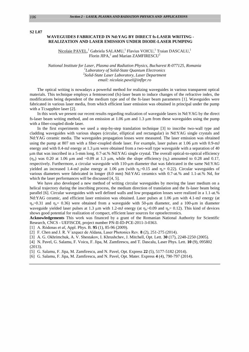
Section 2 – LASER, PLASMA AND RADIATION PHYSICS AND APPLICATIONS
106
S2 L07
WAVEGUIDES FABRICATED IN Nd:YAG BY DIRECT fs-LASER WRITING -
REALIZATION AND LASER EMISSION UNDER DIODE-LASER PUMPING
Nicolaie PAVEL,1 Gabriela SALAMU,
1 Flavius VOICU,
1 Traian DASCALU,
1
Florin JIPA,2 and Marian ZAMFIRESCU
2
National Institute for Laser, Plasma and Radiation Physics, Bucharest R-077125, Romania 1Laboratory of Solid-State Quantum Electronics
2Solid-State Laser Laboratory, Laser Department
email: [email protected]
The optical writing is nowadays a powerful method for realizing waveguides in various transparent optical
materials. This technique employs a femtosecond (fs)-laser beam to induce changes of the refractive index, the
modifications being dependent of the medium type and of the fs-laser beam parameters [1]. Waveguides were
fabricated in various laser media, from which efficient laser emission was obtained in principal under the pump
with a Ti:sapphire laser [2].
In this work we present our recent results regarding realization of waveguide lasers in Nd:YAG by the direct
fs-laser beam writing method, and on emission at 1.06 m and 1.3 m from these waveguides using the pump
with a fiber-coupled diode laser.
In the first experiments we used a step-by-step translation technique [3] to inscribe two-wall type and
cladding waveguides with various shapes (circular, elliptical and rectangular) in Nd:YAG single crystals and
Nd:YAG ceramic media. The waveguides propagation losses were measured. The laser emission was obtained
using the pump at 807 nm with a fiber-coupled diode laser. For example, laser pulses at 1.06 m with 0.9-mJ
energy and with 0.4-mJ energy at 1.3 m were obtained from a two-wall type waveguide with a separation of 40
m that was inscribed in a 5-mm long, 0.7-at.% Nd:YAG single crystal. The overall optical-to-optical efficiency
(o) was 0.20 at 1.06 m and ~0.09 at 1.3 m, while the slope efficiency (s) amounted to 0.28 and 0.17,
respectively. Furthermore, a circular waveguide with 110-m diameter that was fabricated in the same Nd:YAG
yielded an increased 1.4-mJ pulse energy at 1.06 m (with o~0.15 and s= 0.22). Circular waveguides of
various diameters were fabricated in longer (8.0 mm) Nd:YAG ceramics with 0.7-at.% and 1.1-at.% Nd, for
which the laser performances will be discussed [4, 5].
We have also developed a new method of writing circular waveguides by moving the laser medium on a
helical trajectory during the inscribing process, the medium direction of translation and the fs-laser beam being
parallel [6]. Circular waveguides with well defined walls and low propagation losses were realized in a 1.1-at.%
Nd:YAG ceramic, and efficient laser emission was obtained. Laser pulses at 1.06 m with 4.1-mJ energy (at
o~0.31 and s= 0.36) were obtained from a waveguide with 50-m diameter, and a 100-m in diameter
waveguide yielded laser pulses at 1.3 m with 1.2-mJ energy (at o~0.09 and s= 0.12). This kind of devices
shows good potential for realization of compact, efficient laser sources for optoelectronics.
Acknowledgements This work was financed by a grant of the Romanian National Authority for Scientific
Research, CNCS - UEFISCDI, project number PN-II-ID-PCE-2011-3-0363.
[1] A. Ródenas et al, Appl. Phys. B. 95 (1), 85-96 (2009).
[2] F. Chen and J. R. V´azquez de Aldana, Laser Photonics Rev. 8 (2), 251-275 (2014).
[3] A. G. Okhrimchuk, A. V. Shestakov, I. Khrushchev, J. Mitchell, Opt. Lett. 30 (17), 2248-2250 (2005).
[4] N. Pavel, G. Salamu, F. Voicu, F. Jipa, M. Zamfirescu, and T. Dascalu, Laser Phys. Lett. 10 (9), 095802
(2013).
[5] G. Salamu, F. Jipa, M. Zamfirescu, and N. Pavel, Opt. Express 22 (5), 5177-5182 (2014).
[6] G. Salamu, F. Jipa, M. Zamfirescu, and N. Pavel, Opt. Mater. Express 4 (4), 790-797 (2014).
University of Neuchâtel,
FLSH - Faculté des Lettres
et Sciences Humaines
Neuchâtel, Switzerland
24 - 29 August 2014
Europhysics Conference Abstract Volume 38 E
ISBN n° 2-914771-89-4
C O N F E R E N C E D I G E S T
ww
w.e
urop
hoto
n.or
g
6th EPS-QEOD Europhoton Conference
EUROPHOTON SOLID-STATE, FIBRE, AND WAVEGUIDE COHERENT LIGHT SOURCES
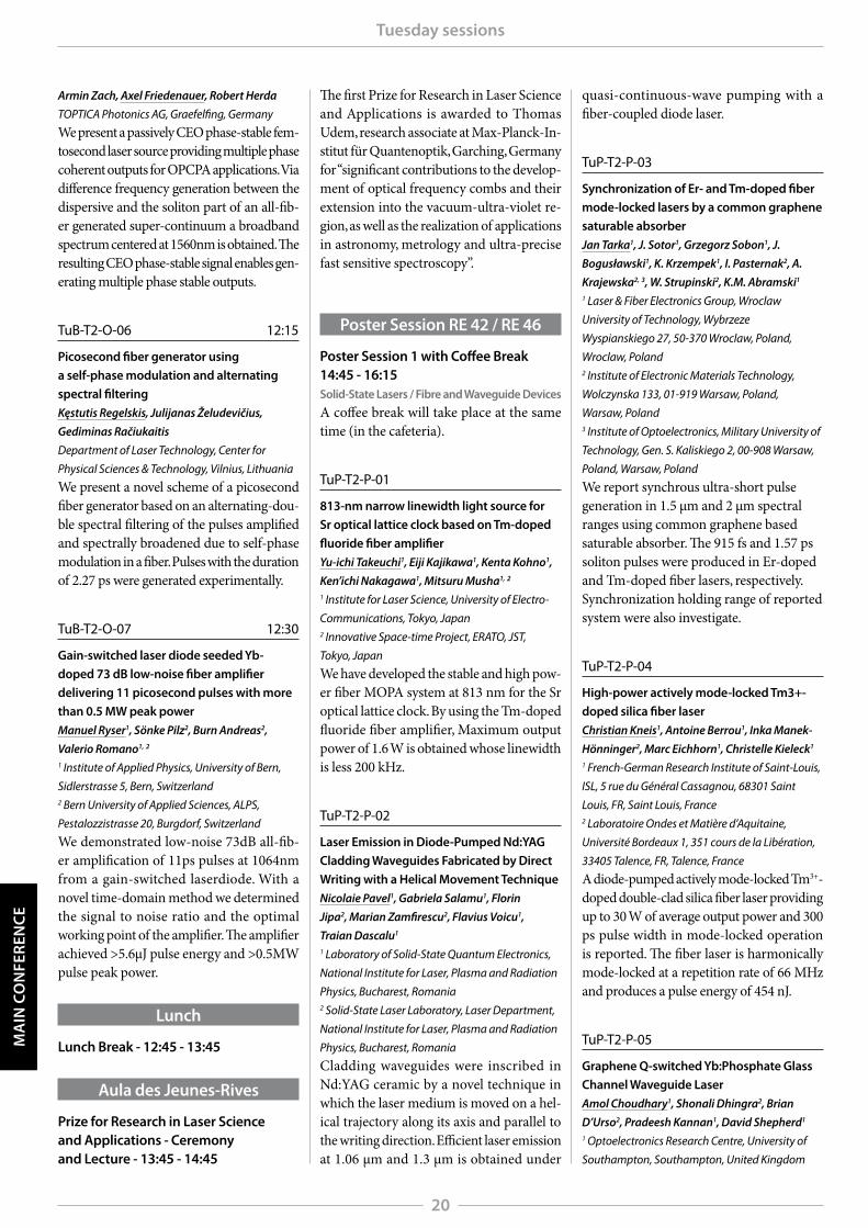
MA
IN C
ON
FER
ENC
ETuesday sessions
20
Armin Zach, Axel Friedenauer, Robert Herda
TOPTICA Photonics AG, Graefelfing, Germany
We present a passively CEO phase-stable fem-tosecond laser source providing multiple phase coherent outputs for OPCPA applications. Via difference frequency generation between the dispersive and the soliton part of an all-fib-er generated super-continuum a broadband spectrum centered at 1560nm is obtained. The resulting CEO phase-stable signal enables gen-erating multiple phase stable outputs.
TuB-T2-O-06 12:15
Picosecond fiber generator using a self-phase modulation and alternating spectral filteringKęstutis Regelskis, Julijanas Želudevičius,
Gediminas Račiukaitis
Department of Laser Technology, Center for
Physical Sciences & Technology, Vilnius, Lithuania
We present a novel scheme of a picosecond fiber generator based on an alternating-dou-ble spectral filtering of the pulses amplified and spectrally broadened due to self-phase modulation in a fiber. Pulses with the duration of 2.27 ps were generated experimentally.
TuB-T2-O-07 12:30
Gain-switched laser diode seeded Yb-doped 73 dB low-noise fiber amplifier delivering 11 picosecond pulses with more than 0.5 MW peak powerManuel Ryser1, Sönke Pilz2, Burn Andreas2,
Valerio Romano1, 2
1 Institute of Applied Physics, University of Bern,
Sidlerstrasse 5, Bern, Switzerland 2 Bern University of Applied Sciences, ALPS,
Pestalozzistrasse 20, Burgdorf, Switzerland
We demonstrated low-noise 73dB all-fib-er amplification of 11ps pulses at 1064nm from a gain-switched laserdiode. With a novel time-domain method we determined the signal to noise ratio and the optimal working point of the amplifier. The amplifier achieved >5.6µJ pulse energy and >0.5MW pulse peak power.
Lunch
Lunch Break - 12:45 - 13:45
Aula des Jeunes-Rives
Prize for Research in Laser Science and Applications - Ceremony and Lecture - 13:45 - 14:45
The first Prize for Research in Laser Science and Applications is awarded to Thomas Udem, research associate at Max-Planck-In-stitut für Quantenoptik, Garching, Germany for “significant contributions to the develop-ment of optical frequency combs and their extension into the vacuum-ultra-violet re-gion, as well as the realization of applications in astronomy, metrology and ultra-precise fast sensitive spectroscopy”.
Poster Session RE 42 / RE 46
Poster Session 1 with Coffee Break 14:45 - 16:15Solid-State Lasers / Fibre and Waveguide Devices
A coffee break will take place at the same time (in the cafeteria).
TuP-T2-P-01
813-nm narrow linewidth light source for Sr optical lattice clock based on Tm-doped fluoride fiber amplifierYu-ichi Takeuchi1, Eiji Kajikawa1, Kenta Kohno1,
Ken’ichi Nakagawa1, Mitsuru Musha1, 2
1 Institute for Laser Science, University of Electro-
Communications, Tokyo, Japan 2 Innovative Space-time Project, ERATO, JST,
Tokyo, Japan
We have developed the stable and high pow-er fiber MOPA system at 813 nm for the Sr optical lattice clock. By using the Tm-doped fluoride fiber amplifier, Maximum output power of 1.6 W is obtained whose linewidth is less 200 kHz.
TuP-T2-P-02
Laser Emission in Diode-Pumped Nd:YAG Cladding Waveguides Fabricated by Direct Writing with a Helical Movement TechniqueNicolaie Pavel1, Gabriela Salamu1, Florin
Jipa2, Marian Zamfirescu2, Flavius Voicu1,
Traian Dascalu1
1 Laboratory of Solid-State Quantum Electronics,
National Institute for Laser, Plasma and Radiation
Physics, Bucharest, Romania 2 Solid-State Laser Laboratory, Laser Department,
National Institute for Laser, Plasma and Radiation
Physics, Bucharest, Romania
Cladding waveguides were inscribed in Nd:YAG ceramic by a novel technique in which the laser medium is moved on a hel-ical trajectory along its axis and parallel to the writing direction. Efficient laser emission at 1.06 μm and 1.3 μm is obtained under
quasi-continuous-wave pumping with a fiber-coupled diode laser.
TuP-T2-P-03
Synchronization of Er- and Tm-doped fiber mode-locked lasers by a common graphene saturable absorberJan Tarka1, J. Sotor1, Grzegorz Sobon1, J.
Bogusławski1, K. Krzempek1, I. Pasternak2, A.
Krajewska2, 3, W. Strupinski2, K.M. Abramski1
1 Laser & Fiber Electronics Group, Wroclaw
University of Technology, Wybrzeze
Wyspianskiego 27, 50-370 Wroclaw, Poland,
Wroclaw, Poland 2 Institute of Electronic Materials Technology,
Wolczynska 133, 01-919 Warsaw, Poland,
Warsaw, Poland 3 Institute of Optoelectronics, Military University of
Technology, Gen. S. Kaliskiego 2, 00-908 Warsaw,
Poland, Warsaw, Poland We report synchrous ultra-short pulse generation in 1.5 µm and 2 µm spectral ranges using common graphene based saturable absorber. The 915 fs and 1.57 ps soliton pulses were produced in Er-doped and Tm-doped fiber lasers, respectively. Synchronization holding range of reported system were also investigate.
TuP-T2-P-04
High-power actively mode-locked Tm3+-doped silica fiber laserChristian Kneis1, Antoine Berrou1, Inka Manek-
Hönninger2, Marc Eichhorn1, Christelle Kieleck1
1 French-German Research Institute of Saint-Louis,
ISL, 5 rue du Général Cassagnou, 68301 Saint
Louis, FR, Saint Louis, France 2 Laboratoire Ondes et Matière d’Aquitaine,
Université Bordeaux 1, 351 cours de la Libération,
33405 Talence, FR, Talence, France
A diode-pumped actively mode-locked Tm3+-doped double-clad silica fiber laser providing up to 30 W of average output power and 300 ps pulse width in mode-locked operation is reported. The fiber laser is harmonically mode-locked at a repetition rate of 66 MHz and produces a pulse energy of 454 nJ.
TuP-T2-P-05
Graphene Q-switched Yb:Phosphate Glass Channel Waveguide LaserAmol Choudhary1, Shonali Dhingra2, Brian
D’Urso2, Pradeesh Kannan1, David Shepherd1
1 Optoelectronics Research Centre, University of
Southampton, Southampton, United Kingdom
Laser Emission from Diode-Pumped Nd:YAG Cladding Waveguides
Fabricated by Direct Writing with a Helical Movement Technique
N. Pavel1,*
, G. Salamu1, F. Jipa
2, M. Zamfirescu
2, F. Voicu
1, T. Dascalu
1
1Laboratory of Solid-State Quantum Electronics, National Institute for Laser, Plasma and Radiation Physics, Bucharest 077125, Romania 2Solid-State Laser Laboratory, Laser Department, National Institute for Laser, Plasma and Radiation Physics, Bucharest 077125, Romania
*nicolaie [email protected]
Due to their compactness and the possibility to deliver output performances similar to those of the bulk
material, with even lower threshold, the waveguide lasers are good candidates in optoelectronics for realization
of different photonic integrated circuits. Various techniques can be used to fabricate a laser waveguide [1]. The
optical writing, which relies on changes of the refractive index induced by a femtosecond (fs)-laser beam, is now
recognized as a powerful tool for obtaining waveguides in various transparent optical materials. Many works
have reported inscribing of two-wall type waveguides, from which laser emission was obtained using in
principal the pump with Ti:sapphire lasers [2]. A step forward toward obtaining of a compact waveguide laser
(which has to include also the pump source, in principle a diode laser) was the fabrication of a cladding
waveguide by the translation technique [3]. In this work we report realization of circular waveguides in Nd:YAG
ceramic by direct writing with a fs-laser beam, using the movement of the laser medium on a helical trajectory
[4, 5]. Efficient emission at 1.06 µm and 1.3 µm was obtained under the pump with a fiber-coupled diode laser.
The classical writing method [3] is shown in Fig. 1a. With this scheme many tracks are inscribed on the
waveguide contour using step-by-step translation of the medium. In the new inscribing method (presented in Fig.
1b), the Nd:YAG is 90o rotated on the motorized stage; the medium is moved on a helical trajectory and,
furthermore, the helix axis (i.e. the translation direction) and the fs-laser beam are parallel. In this work we have
realized circular waveguides by both techniques. With the classical method an inscribed wall is not uniform,
because a space of unmodified material is left between any consecutive tracks (Fig. 1c); these regions with
unchanged refractive index increase the waveguide propagation losses. On the other hand, helical movement of
Nd:YAG enabled realization of circular waveguides with smooth and well defined walls, as shown in Fig. 1d.
Fig. 1 Inscribing waveguides by (a) step-by-step translation and by (b) helical movement. Fig. 2 Laser emission at 1.06 µm.
Waveguides with φ= 100 µm made by (c) translation and following (d) a helical motion. OCM: out-coupling mirror; T: transmission.
Experiments concluded that the helical motion provides waveguides with lower propagation losses compared
to those of similar structures realized by classical translation of the medium. Laser emission was obtained under
the pump at 807 nm with a fiber-coupled diode that was operated in quasi-continuous-wave (quasi-cw) regime.
A short plane-plane resonator was used. For example, a 100-µm diameter waveguide inscribed by translation in a
5-mm thick, 1.1-at.% Nd:YAG ceramic (CW-SST, Fig. 1c) yielded pulses at 1.06 µm with energy Ep= 2.15 mJ
(for Epump= 13.1 mJ) at slope ηs= 0.20 (Fig. 2). The waveguide realized by helical movement (CW-HM, Fig. 1d)
increased Ep at 3.2 mJ and improved ηs at 0.31. Similar behavior was obtained for the emission at 1.3 µm: Ep
reached 0.8 mJ for CW-SST and it was raised to 1.2 mJ by the CW-HM waveguide. Cw operation was also
achieved. This is the first time when cladding waveguides are inscribed by helical movement of the medium, and
this approach could enable realization of efficient integrated waveguides lasers pumped by diode lasers.
Work financed by project PN-II-ID-PCE-2011-3-0363 of the Romanian National Authority for Scientific Research, CNCS - UEFISCDI.
[1] C. Grivas, Progress in Quantum Electron. 35, 159-239 (2011).
[2] F. Chen and J. R. V´azquez de Aldana, Laser Photonics Rev. 8, 251-275 (2014).
[3] A. G. Okhrimchuk, A. V. Shestakov, I. Khrushchev and J. Mitchell, Opt. Lett. 30, 2248-2250 (2005).
[4] O. Caulier, D.-L. Coq, E. Bychkov, and P Masselin, Opt. Lett. 38, 4212-4215 (2013).
[5] G. Salamu, F. Jipa, M. Zamfirescu, and N. Pavel, Opt. Mater. Express 4, 790-797 (2014).

ISCP 2014
Orăștie, Romania23rd - 26th September 2014
55th International Student Conference on Photonics
of AbstractsBook
I n t e r n a t i o n a l S t u d e n t C o n f e r e n c e o n P h o t o n i c s 2 0 1 4
17
O . 0 2
Laser Emission from Diode-Pumped Nd:YAG Waveguide Lasers Realized by Femtosecond-Writing Technique
G. Salamu1, 3, F. Jipa2, 3, M. Zamfirescu2, F. Voicu1, 3, N. Pavel1
1Laboratory of Solid-State Quantum Electronics
National Institute for Laser, Plasma and Radiation Physics, Bucharest R-077125, Romania 2Solid- State Laser Laboratory, Laser Department
National Institute for Laser, Plasma and Radiation Physics, Bucharest R-077125, Romania 3Doctoral School of Physics, University of Bucharest, Romania
e-mail of corresponding author: [email protected]
Femtosecond (fs) laser pulses are becoming an important tool for three-dimensional modifications in various materials. The pulses interact nonlinearly with the material [1], thus a variation of the refractive index appears in the irradiated region [2]. Waveguiding is possible in the volume confined between the written tracks (double-wall or more complex structures) [3].
In this work we report on realization of circular cladding waveguides in Nd:YAG ceramic media by direct femtosecond-laser writing with a helical translation technique. Efficient laser emission at 1.06 m and 1.3 μm is obtained under the pump at 808 nm with a fiber-coupled diode laser. The laser medium was a 5.0-mm thick, 1.1-at. % Nd:YAG ceramic (Baikowski Co. Ltd., Japan). For inscribing we used a chirped pulsed amplified system (Clark CPA-2101) that delivered laser pulses at 775 nm with duration of 200 fs, at 2-kHz repetition rate and energy up to 0.6 mJ. The laser crystal was moved along a helical trajectory during the writing process [4], thus eliminating the regions with unchanged refractive index as obtained in the classical step-by-step technique [5]. Laser pulses with 3.4-mJ energy at 1.06 μm and 1.2 mJ at 1.3 μm under the pump with 13.1 mJ at 807 nm are obtained from a circular waveguide of 100-m diameter. The helical movement of the laser medium during fs-laser writing allows realization of efficient integrated lasers consisting of cladding waveguides pumped by diode lasers. Acknowledgments: This work was financed by a grant of the Romanian National Authority for Scientific Research, CNCS - UEFISCDI, project number PN-II-ID-PCE-2011-3-0363. References [1] B. C. Stuart, M. D. Feit, S. Herman, A. M. Rubenchik, B. W. Shore, and M. D. Perry, Phys. Rev. B 53 (4), 1749(1996). [2] A. Ródenas, G.A. Torchia, G. Lifante, E. Cantelar, J. Lamela, F. Jaque, L. Roso, D. Jaque, Appl. Phys. B 95, 85 (2009). [3] J. Thomas,M. Heinrich, J. Burghoff, S. Nolte, A. Ancona, A. Tünnermann, Appl. Phys. Lett. 91, 151108 (2007). [4] G. Salamu, F. Jipa, M. Zamfirescu, and N. Pavel, Opt. Mater. Express 4, 790 (2014). [5] A. G. Okhrimchuk, A. V. Shestakov, I. Khrushchev, J. Mitchell, Opt. Lett. 30, 2248 (2005).

Advanced Solid State Lasers Conference • 16 ‐ 21 November 2014
The Conference and Exhibition
Advanced Solid State Lasers (ASSL)
Conference Program
16 - 21 November 2014
Hilton Shanghai Hongqiao
Shanghai, China
Table of Contents
Chairs’ Welcome Letter………………….………...…………...…...………...…2
Program Committee…………...…....………...…………...…...…………..…...5
Short Courses.....……………..…………...……………...……...…………........6
Special Events………………...…………………...…………...………………..11
General Information……………………...……...…………...……..……….….17
Explanation of Session Codes…………………...…………...………….……..19
Agenda of Sessions…………….……………...………………...……….……...20
Abstracts...……………………………………...…………...……...…………….24
Key to Authors and Presiders.......…………...……………...………...….........63
Sponsors List.......…………...……………...………...…..................................70
Technical Digest Access……………………...…………...…...…Inside Back Cover

ATu2A.26.pdf Advanced Solid State Lasers (ASSL) © OSA 2014
Efficient Laser Emission under 880-nm Diode-Laser
Pumping of Cladding Waveguides Inscribed in Nd:YVO4
by Femtosecond-Laser Writing Technique
Nicolaie Pavel1,*
, Gabriela Salamu1,3
, Florin Jipa2,3
, and Marian Zamfirescu2
National Institute for Laser, Plasma and Radiation Physics, Bucharest R-077125, Romania
1 Laboratory of Solid-State Quantum Electronics 2 Laser Department, Solid-State Laser Laboratory
3 Doctoral School of Physics, University of Bucharest, Bucharest, Romania *E-mail: [email protected]
Abstract: Efficient 1.06-µm and 1.34-µm laser emission from cladding waveguides inscribed by
femtosecond-laser writing technique in Nd:YVO4 has been obtained using diode laser pumping at
880 nm, directly into the 4F3/2 emitting level of Nd:YVO4.
@ 2014 Optical Society of America OCIS codes: (140.0140) Lasers and laser optics; (140.3530) Lasers, neodymium; (230.7380) Waveguides, channelled.
Compact laser systems of interest for miniature, integrated optical devices can be realized using a waveguide
configuration [1]. Such geometry has the advantages of low threshold of emission and of good overlap between the
pump beam and the laser beam. Recently, the inscribing with a femtosecond (fs)-laser beam [2] has been
demonstrated to be a powerful tool for realizing waveguide lasers in many crystalline laser media [3]. Among these
waveguides, a cladding waveguide, for the first time demonstrated in Nd:Y3Al5O12 (Nd:YAG) [4], consists of a
large number of tracks (with modified refraction index) that surround an unchanged region of the laser material (the
core). Such a structure can be made in different shapes and sizes that can fit the dimensions of an array or of a fiber-
coupled diode laser [4, 5]. Recently, using the pump with fiber-coupled diode laser we have demonstrated laser
emission from cladding waveguides realized in Nd:YAG single-crystal and ceramic media [6, 7].
Besides Nd:YAG, Nd-vanadates show attractive spectroscopic features (like high absorption and emission
cross sections) and good thermal properties that recommend these media for miniature lasers. To date, cladding
waveguides were inscribed by fs-laser beam direct writing in Nd:YVO4 [8] and Nd:GdVO4 [9], and laser emission
at 1.06 µm was reported using the pump at 808 nm with Ti:sapphire laser. In this work we report efficient laser
emission at 1.06 µm and 1.34 µm from circular cladding waveguides inscribed in Nd:YVO4. The pump was made
with a fiber-coupled diode laser at 808 nm, into the highly-absorbing 4F5/2 level, but also at 880 nm, directly into the
4F3/2 emitting level. The reduction of the quantum defect between the pump and the laser wavelength [10, 11]
enables the increase of the waveguides laser performances for the pump at 880 nm in comparison with the pump at
808 nm; to our best knowledge this is the first demonstration of such laser systems. Laser pulses at 1.06 µm with
3.8-mJ energy (absorbed pump pulse energy of 10.4 mJ at 880 nm) at slope efficiency (ηsa) of 0.38, and continuous-
wave (cw) output power of 1.5 W for 5.5-W absorbed power at 880 nm (with slope ηsa= 0.28) were obtained from a
circular waveguide of 100-µm diameter that was inscribed in a 5-mm long, 0.7-at.% Nd:YVO4 crystal.
The experimental set-up that was used to inscribe tracks in Nd:YVO4 was similar to that described in our
previous works [6, 7]. The fs laser was a Clark CPA-2101 system, yielding pulses at 775 nm with energy up to 1 mJ,
duration of 200 fs and 2-kHz repetition rate. In the experiments we used two crystals, a 5-mm long, 0.7-at.%
Nd:YVO4 and a 8-mm long, 0.5-at.% Nd:YVO4. The energy of the fs-laser beam was adjusted by a combination of
half-wave plate, a polarizer and a neutral filter. Then, a 20× microscope objective with a numerical aperture NA=
0.40 was used to focus the fs-laser beam into each crystal. The tracks were positioned ~5 µm apart each other, and
were inscribed at 50-µm/s speed of the translation stage with energy of the fs-laser pulses below 0.3 µJ.
Circular cladding waveguides with 100-µm diameter were realized in the Nd:YVO4 crystals; these will be
denoted by CWG-1 for the 0.7-at.% Nd:YVO4 crystal and by CWG-2 for the 0.5-at.% Nd:YVO4 crystal. Also, a
square (80 µm × 80 µm) cladding waveguide (SWG) was written in the 0.5-at.% Nd:YVO4 medium. All
waveguides were centred at 500-µm depth below the Nd:YVO4 side that faced the focussing objective. Microscope
images (in reflexion mode) of waveguides CWG-1 and SWG are presented in Fig. 1a and 1b, respectively.
Furthermore, typical images (that were recorded with a Spiricon camera, model SP620U) of the waveguides during
laser operation are shown in Fig. 1c for waveguide CWG-1 and in Fig. 1d for waveguide SWG.
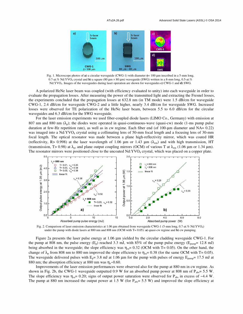
ATu2A.26.pdf Advanced Solid State Lasers (ASSL) © OSA 2014
Fig. 1. Microscope photos of a) a circular waveguide (CWG-1) with diameter φ= 100 µm inscribed in a 5-mm long,
0.7-at.% Nd:YVO4 crystal and b) a square (80 µm × 80 µm) waveguide (SWG) written in a 8-mm long, 0.5-at.%
Nd:YVO4. Images of the waveguides during laser operation are shown for waveguides c) CWG-1 and d) SWG.
A polarized HeNe laser beam was coupled (with efficiency evaluated to unity) into each waveguide in order to
evaluate the propagation losses. After measuring the power of the transmitted light and extracting the Fresnel losses,
the experiments concluded that the propagation losses at 632.8 nm (in TM mode) were 1.5 dB/cm for waveguide
CWG-1, 2.4 dB/cm for waveguide CWG-2 and a little higher, nearly 3.4 dB/cm for waveguide SWG. Increased
losses were observed for TE polarization of the HeNe laser beam, between 5.5 to 6.0 dB/cm for the circular
waveguides and 6.3 dB/cm for the SWG waveguide.
For the laser emission experiments we used fiber-coupled diode lasers (LIMO Co., Germany) with emission at
807 nm and 880 nm (λp); the diodes were operated in quasi-continuous-wave (quasi-cw) mode (1-ms pump pulse
duration at few-Hz repetition rate), as well as in cw regime. Each fiber end (of 100-µm diameter and NA= 0.22)
was imaged into a Nd:YVO4 crystal using a collimating lens of 50-mm focal length and a focusing lens of 30-mm
focal length. The optical resonator was made between a plane high-reflectivity mirror, which was coated HR
(reflectivity, R> 0.998) at the laser wavelength of 1.06 µm or 1.43 µm (λem) and with high transmission, HT
(transmission, T> 0.98) at λp, and plane output coupling mirrors (OCM) of various T at λem (1.06 µm or 1.34 µm).
The resonator mirrors were positioned close to the uncoated Nd:YVO4 crystal, which was placed on a copper plate.
Fig. 2. Comparison of laser emission characteristics at 1.06 µm obtained from waveguide CWG-1 (5-mm long, 0.7-at.% Nd:YVO4)
under the pump with diode lasers at 880 nm and 808 nm (OCM with T= 0.05): a) quasi-cw regime and b) cw pumping.
Figure 2a presents the laser pulse energy at 1.06 µm yielded by the circular cladding waveguide CWG-1. For
the pump at 808 nm, the pulse energy (Ep) reached 3.3 mJ, with 85% of the pump pulse energy (Epump= 12.8 mJ)
being absorbed in the waveguide; the slope efficiency was ηsa= 0.32 (OCM with T= 0.05). On the other hand, the
change of λp from 808 nm to 880 nm improved the slope efficiency to ηsa= 0.38 (for the same OCM with T= 0.05).
The waveguide delivered pulses with Ep= 3.8 mJ at 1.06 µm for the pump with pulses of energy Epump= 17.5 mJ at
880 nm; the absorption efficiency at 880 nm was ηa~0.60.
Improvements of the laser emission performances were observed also for the pump at 880 nm in cw regime. As
shown in Fig. 2b, the CWG-1 waveguide outputted 0.9 W for an absorbed pump power at 808 nm of Pabs= 5.5 W.
The slope efficiency was ηsa= 0.20; signs of output power saturation were observed for Pabs in excess of ~4.4 W.
The pump at 880 nm increased the output power at 1.5 W (for Pabs= 5.5 W) and improved the slope efficiency at
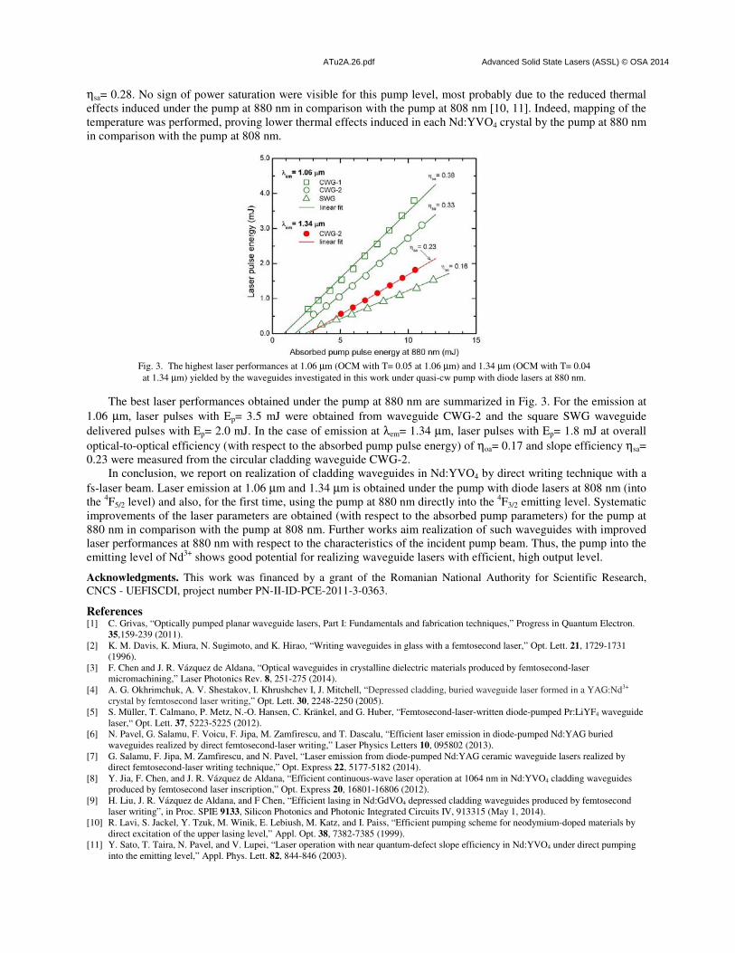
ATu2A.26.pdf Advanced Solid State Lasers (ASSL) © OSA 2014
ηsa= 0.28. No sign of power saturation were visible for this pump level, most probably due to the reduced thermal
effects induced under the pump at 880 nm in comparison with the pump at 808 nm [10, 11]. Indeed, mapping of the
temperature was performed, proving lower thermal effects induced in each Nd:YVO4 crystal by the pump at 880 nm
in comparison with the pump at 808 nm.
Fig. 3. The highest laser performances at 1.06 µm (OCM with T= 0.05 at 1.06 µm) and 1.34 µm (OCM with T= 0.04
at 1.34 µm) yielded by the waveguides investigated in this work under quasi-cw pump with diode lasers at 880 nm.
The best laser performances obtained under the pump at 880 nm are summarized in Fig. 3. For the emission at
1.06 µm, laser pulses with Ep= 3.5 mJ were obtained from waveguide CWG-2 and the square SWG waveguide
delivered pulses with Ep= 2.0 mJ. In the case of emission at λem= 1.34 µm, laser pulses with Ep= 1.8 mJ at overall
optical-to-optical efficiency (with respect to the absorbed pump pulse energy) of ηoa= 0.17 and slope efficiency ηsa=
0.23 were measured from the circular cladding waveguide CWG-2.
In conclusion, we report on realization of cladding waveguides in Nd:YVO4 by direct writing technique with a
fs-laser beam. Laser emission at 1.06 µm and 1.34 µm is obtained under the pump with diode lasers at 808 nm (into
the 4F5/2 level) and also, for the first time, using the pump at 880 nm directly into the
4F3/2 emitting level. Systematic
improvements of the laser parameters are obtained (with respect to the absorbed pump parameters) for the pump at
880 nm in comparison with the pump at 808 nm. Further works aim realization of such waveguides with improved
laser performances at 880 nm with respect to the characteristics of the incident pump beam. Thus, the pump into the
emitting level of Nd3+
shows good potential for realizing waveguide lasers with efficient, high output level.
Acknowledgments. This work was financed by a grant of the Romanian National Authority for Scientific Research,
CNCS - UEFISCDI, project number PN-II-ID-PCE-2011-3-0363.
References [1] C. Grivas, “Optically pumped planar waveguide lasers, Part I: Fundamentals and fabrication techniques,” Progress in Quantum Electron.
35,159-239 (2011).
[2] K. M. Davis, K. Miura, N. Sugimoto, and K. Hirao, “Writing waveguides in glass with a femtosecond laser,” Opt. Lett. 21, 1729-1731
(1996).
[3] F. Chen and J. R. Vázquez de Aldana, “Optical waveguides in crystalline dielectric materials produced by femtosecond-laser
micromachining,” Laser Photonics Rev. 8, 251-275 (2014).
[4] A. G. Okhrimchuk, A. V. Shestakov, I. Khrushchev I, J. Mitchell, “Depressed cladding, buried waveguide laser formed in a YAG:Nd3+
crystal by femtosecond laser writing,” Opt. Lett. 30, 2248-2250 (2005).
[5] S. Müller, T. Calmano, P. Metz, N.-O. Hansen, C. Kränkel, and G. Huber, “Femtosecond-laser-written diode-pumped Pr:LiYF4 waveguide
laser,“ Opt. Lett. 37, 5223-5225 (2012).
[6] N. Pavel, G. Salamu, F. Voicu, F. Jipa, M. Zamfirescu, and T. Dascalu, “Efficient laser emission in diode-pumped Nd:YAG buried
waveguides realized by direct femtosecond-laser writing,” Laser Physics Letters 10, 095802 (2013).
[7] G. Salamu, F. Jipa, M. Zamfirescu, and N. Pavel, “Laser emission from diode-pumped Nd:YAG ceramic waveguide lasers realized by
direct femtosecond-laser writing technique,” Opt. Express 22, 5177-5182 (2014).
[8] Y. Jia, F. Chen, and J. R. Vázquez de Aldana, “Efficient continuous-wave laser operation at 1064 nm in Nd:YVO4 cladding waveguides
produced by femtosecond laser inscription,” Opt. Express 20, 16801-16806 (2012).
[9] H. Liu, J. R. Vázquez de Aldana, and F Chen, “Efficient lasing in Nd:GdVO4 depressed cladding waveguides produced by femtosecond
laser writing”, in Proc. SPIE 9133, Silicon Photonics and Photonic Integrated Circuits IV, 913315 (May 1, 2014).
[10] R. Lavi, S. Jackel, Y. Tzuk, M. Winik, E. Lebiush, M. Katz, and I. Paiss, “Efficient pumping scheme for neodymium-doped materials by
direct excitation of the upper lasing level,” Appl. Opt. 38, 7382-7385 (1999).
[11] Y. Sato, T. Taira, N. Pavel, and V. Lupei, “Laser operation with near quantum-defect slope efficiency in Nd:YVO4 under direct pumping
into the emitting level,” Appl. Phys. Lett. 82, 844-846 (2003).