Model Cadru
32
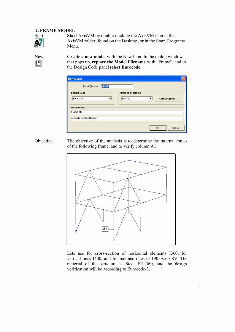
1 2. FRAME MODEL Start Start AxisVM by double-clicking the AxisVM icon in the AxisVM folder, found on the Deskto p, or in the Start, Programs Menu. New Create a new model with the New Icon. In the dialog window that pops up, replace the Model Filename with “Frame”, and in the Design Code panel select Eurocode. Objective The objective of the analysis is to determine the internal forces of the following frame, and to verify column A1. Lets use for cross-section of horizontal elements I360, for vertical ones I400, and for inclined ones O 190.0x5.0 SV. The material of the structure is Steel FE 360, and the design verification will be according to Eurocode-3.
-
Upload
alex-timoc -
Category
Documents
-
view
235 -
download
0
Transcript of Model Cadru
8/3/2019 Model Cadru
http://slidepdf.com/reader/full/model-cadru 1/32
1
2. FRAME MODELStart Start AxisVM by double-clicking the AxisVM icon in the
AxisVM folder, found on the Desktop, or in the Start, ProgramsMenu.
New Create a new model with the New Icon. In the dialog windowthat pops up, replace the Model Filename with “Frame”, and inthe Design Code panel select Eurocode .
Objective The objective of the analysis is to determine the internal forcesof the following frame, and to verify column A1.
Lets use for cross-section of horizontal elements I360, for vertical ones I400, and for inclined ones O 190.0x5.0 SV. Thematerial of the structure is Steel FE 360, and the designverification will be according to Eurocode-3.

8/3/2019 Model Cadru
http://slidepdf.com/reader/full/model-cadru 2/32
2
By default the Z-axis of the global coordinate system pointsupward. It has relevance for the direction of gravity, this will bedetailed later.
Coordinate
System
In the lower left corner of the graphics area is the global
coordinate system symbol. The positive direction is marked bythe corresponding capital letter (X, Y, Z). The default coordinatesystem of a new model is the X-Z coordinate system. It isimportant to note that unless changed the gravity acts along the – Z direction.
In a new model, the global coordinate default location of thecursor is the bottom left corner of the graphic area, and is set toX=0, Y=0, Z=0.
You can change to the relative coordinate values by pressing the
‘d’ labeled button on the left of the Coordinate Window. (Hint:In the right column of the coordinate window you can specify points in cylindrical or spherical coordinate systems). The originof the relative coordinate system is marked by a thick blue X.
The first step is to create the geometry of the structure. Geometry Click the Geometry tab , below the menu bar. The Geometry
Toolbar appears below the tabs. The geometry of the structurewill be created with the Line Tool.
Line Hold down the left mouse button while the cursor is on theLine Tool Icon will bring up the following Line Type icon bar:
Polygon Lets click on the Polygon icon , which is the second from left.When the Polygon is chosen, the Relative coordinate systemautomatically changes to the local system (‘d’ prefix)
The polygon coordinates for the frame model can be drawn withthe mouse, or by typing in their numerical values.

8/3/2019 Model Cadru
http://slidepdf.com/reader/full/model-cadru 3/32
3
Set the first point (node) of the line by typing in these entries :
X=0Y=0Z=0
Finish specifying the first line point by pressing Enter . The firstnode of the frame model is now also the global coordinatesorigin point.
To enter the first line (node) of the frame model, enter thefollowing values :
X=0Y=0
Z=3.5, Enter
To define the second line of the frame model, enter the
following values : X=6Y=0
Z=0, Enter
To define the third line of the frame model, enter the followingvalues :
X=0Y=0
Z=-3.5, Enter (Note: Negative value)
Exit from the Polygon command by pressing Esc twice.The following picture is obtained:
Translate Copy the structure vertically upward with the Translate Icon.For this click the Translate Icon , select the horizontal line and
8/3/2019 Model Cadru
http://slidepdf.com/reader/full/model-cadru 4/32
4
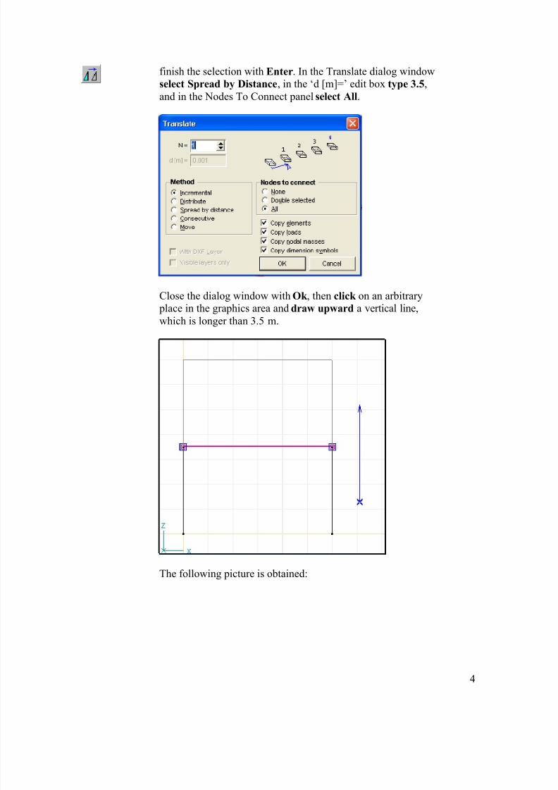
finish the selection with Enter . In the Translate dialog windowselect Spread by Distance , in the ‘d [m]=’ edit box type 3.5 ,and in the Nodes To Connect panel select All .
Close the dialog window with Ok , then click on an arbitrary place in the graphics area and draw upward a vertical line,which is longer than 3.5 m.
The following picture is obtained:

8/3/2019 Model Cadru
http://slidepdf.com/reader/full/model-cadru 5/32
5
CoordinateSystem
Switch to Z-Y plane.You should see this picture:
Translate Select the Translate Icon so you can Copy this part of themodel geometry structure. In the Selection Icon bar use the Allcommand (the asterisk). The selected elements color willchange:

8/3/2019 Model Cadru
http://slidepdf.com/reader/full/model-cadru 6/32
6
Finishing the selection with Ok , in the dialog window select theConsecutive method , then in the Nodes to Connect panel selectthe Double Selected option.
Close this dialog window with Ok . Now you must select thenodes to connect. Use a selection window according to the
picture below on the left. The picture on the right shows theresult of your selection:

8/3/2019 Model Cadru
http://slidepdf.com/reader/full/model-cadru 7/32
7
Specify the first displacement vector by entering the followingvalues :
X=0Y=5Z=0, enter.
Enter the second vector:X=0Y=5
Z=0, enter.Enter the third vector:
X=0Y=5
Z=0, enter.
Esc twice to exit from the command. The following picture will be seen:

8/3/2019 Model Cadru
http://slidepdf.com/reader/full/model-cadru 8/32
8
CoordinateSystem
Switch to perspective View . The colums should be on thevertical Z-axis. Use the pan function as needed to bring themodel to this perspective.
When you close the dialog bar this settings will remain active.
Polygon Click the Polygon Icon . Draw a segment from the bottom of A1 column to the middle of the beam in Y direction:
Continue with a segment to the bottom of the middle column:
8/3/2019 Model Cadru
http://slidepdf.com/reader/full/model-cadru 9/32
9
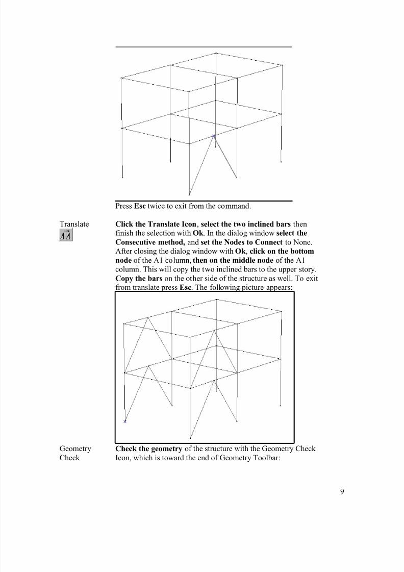
Press Esc twice to exit from the command.
Translate Click the Translate Icon , select the two inclined bars thenfinish the selection with Ok . In the dialog window select theConsecutive method, and set the Nodes to Connect to None.After closing the dialog window with Ok , click on the bottomnode of the A1 column, then on the middle node of the A1column. This will copy the two inclined bars to the upper story.Copy the bars on the other side of the structure as well. To exitfrom translate press Esc . The following picture appears:
GeometryCheck
Check the geometry of the structure with the Geometry Check Icon, which is toward the end of Geometry Toolbar:

8/3/2019 Model Cadru
http://slidepdf.com/reader/full/model-cadru 10/32
10
In the dialog window you can set the maximum tolerance for merging nodes, and you can specify whether to search or not for unattached nodes or lines.
When the check is finished a summary will appear.
Elements The next step is to create the finite elements. For this click onthe Elements tab.
Line Elements To create the finite elements for beams or columns use the LineElements Icon. To define the materials for the Columns, Click the icon , then select the the vertical lines ( all columns) byclicking them or by selection windows as in the picture.
8/3/2019 Model Cadru
http://slidepdf.com/reader/full/model-cadru 11/32
11
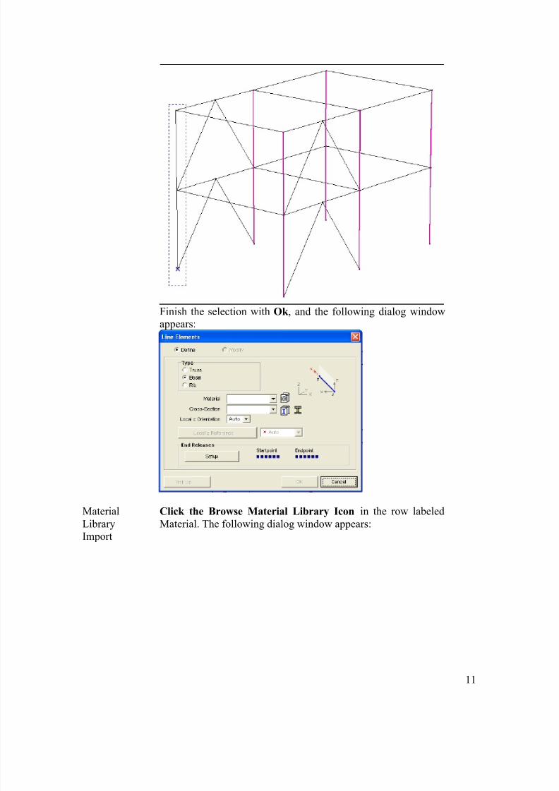
Finish the selection with Ok , and the following dialog windowappears:
MaterialLibraryImport
Click the Browse Material Library Icon in the row labeledMaterial. The following dialog window appears:
8/3/2019 Model Cadru
http://slidepdf.com/reader/full/model-cadru 12/32
12
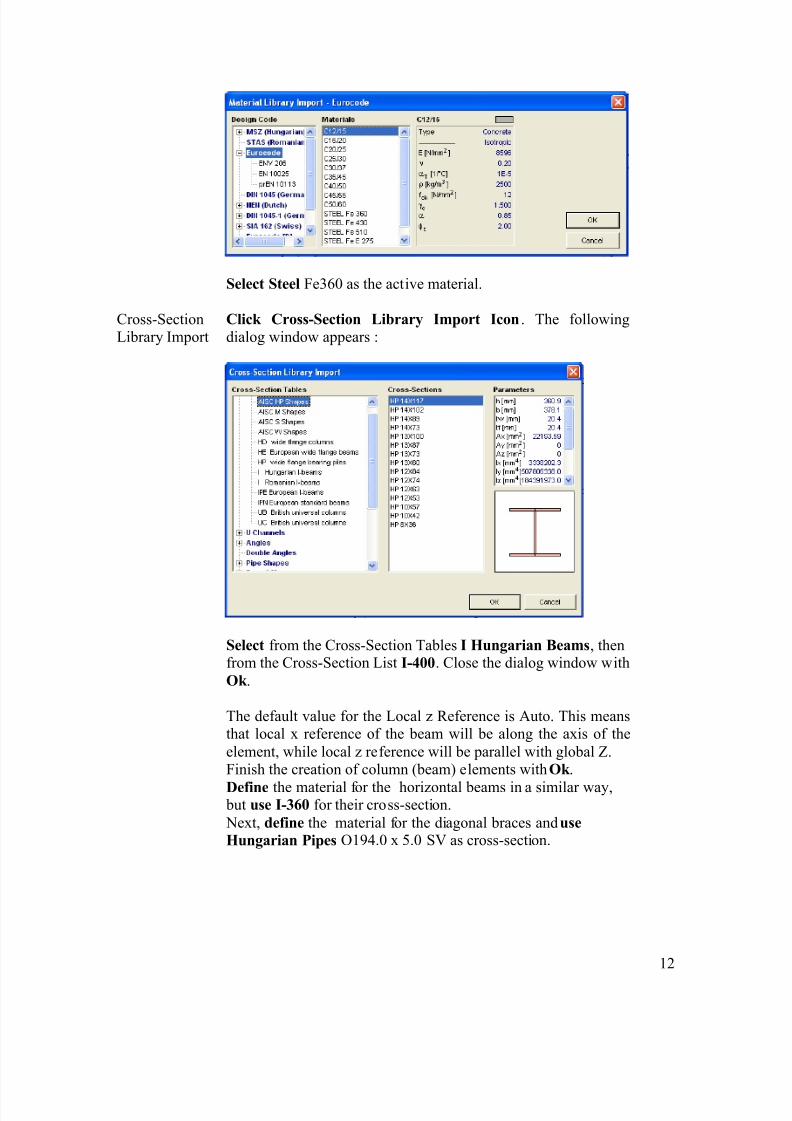
Select Steel Fe360 as the active material.
Cross-SectionLibrary Import
Click Cross-Section Library Import Icon . The followingdialog window appears :
Select from the Cross-Section Tables I Hungarian Beams , thenfrom the Cross-Section List I-400 . Close the dialog window withOk .
The default value for the Local z Reference is Auto. This meansthat local x reference of the beam will be along the axis of theelement, while local z reference will be parallel with global Z.Finish the creation of column (beam) elements with Ok .Define the material for the horizontal beams in a similar way,
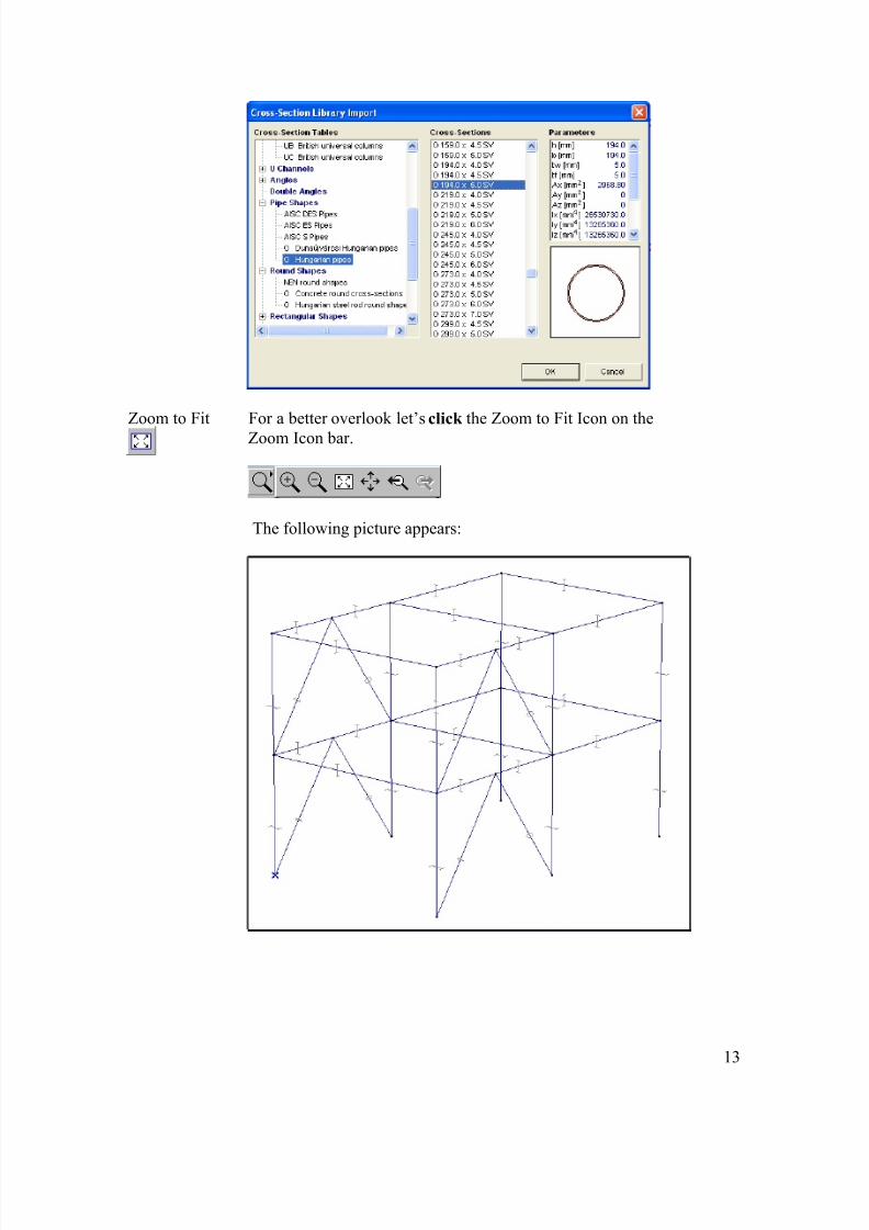
but use I-360 for their cross-section. Next, define the material for the diagonal braces and useHungarian Pipes O194.0 x 5.0 SV as cross-section.
8/3/2019 Model Cadru
http://slidepdf.com/reader/full/model-cadru 13/32
13
Zoom to Fit For a better overlook let’s click the Zoom to Fit Icon on theZoom Icon bar.
The following picture appears:

8/3/2019 Model Cadru
http://slidepdf.com/reader/full/model-cadru 14/32
14
Nodal Support Click the Nodal Support Icon, select all 6 column’s bottom nodeand finish the selection with Ok. The following dialog windowappears:
In this dialog window you can set the node support conditions.Let’s assume pinned supports in all these nodes, so set therotational stiffness Rxx, Ryy, Rzz to 0.
Finish the creation of nodal supports with Ok , and the supportsymbols will appear.
8/3/2019 Model Cadru
http://slidepdf.com/reader/full/model-cadru 15/32
15
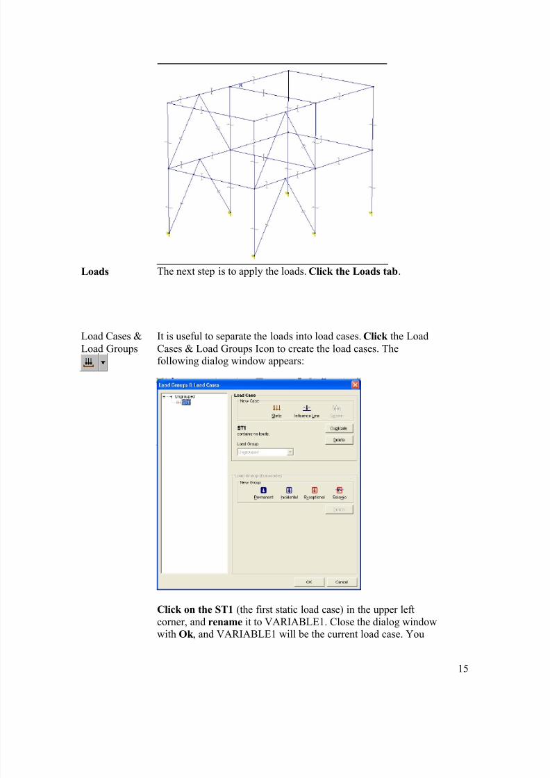
Loads The next step is to apply the loads. Click the Loads tab .
Load Cases &Load Groups
It is useful to separate the loads into load cases. Click the LoadCases & Load Groups Icon to create the load cases. Thefollowing dialog window appears:
Click on the ST1 (the first static load case) in the upper leftcorner, and rename it to VARIABLE1. Close the dialog windowwith Ok , and VARIABLE1 will be the current load case. You
8/3/2019 Model Cadru
http://slidepdf.com/reader/full/model-cadru 16/32
16
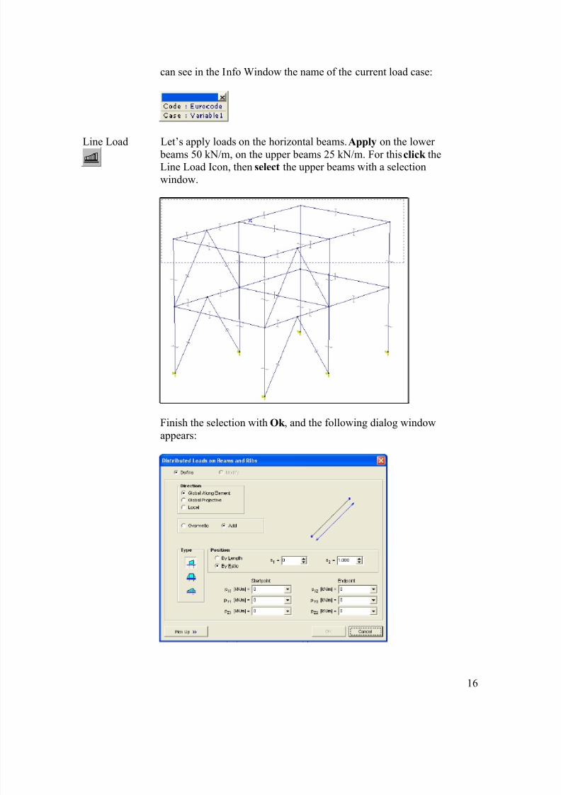
can see in the Info Window the name of the current load case:
Line Load Let’s apply loads on the horizontal beams. Apply on the lower beams 50 kN/m, on the upper beams 25 kN/m. For this click theLine Load Icon, then select the upper beams with a selectionwindow.
Finish the selection with Ok , and the following dialog windowappears:
8/3/2019 Model Cadru
http://slidepdf.com/reader/full/model-cadru 17/32
17
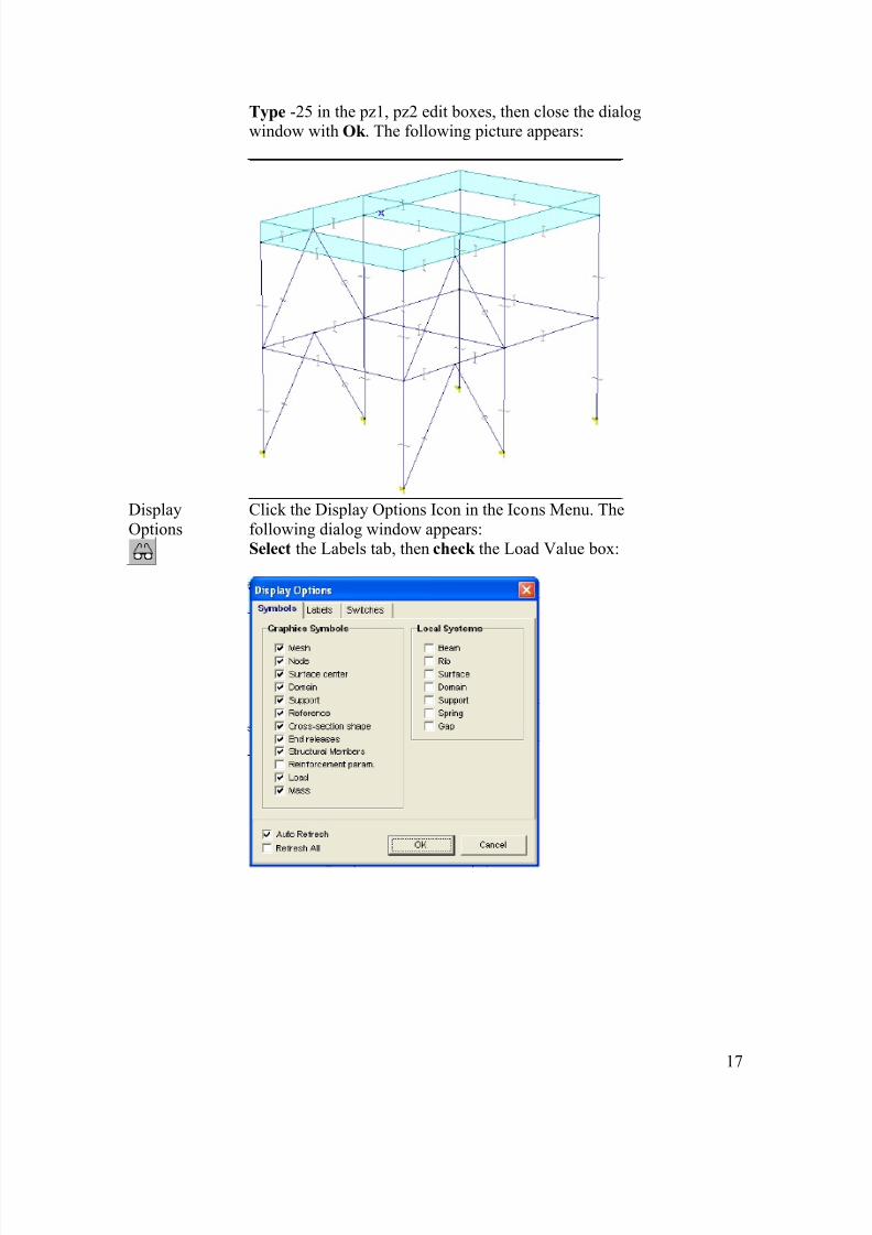
Type -25 in the pz1, pz2 edit boxes, then close the dialogwindow with Ok . The following picture appears:
DisplayOptions
Click the Display Options Icon in the Icons Menu. Thefollowing dialog window appears:Select the Labels tab, then check the Load Value box:

8/3/2019 Model Cadru
http://slidepdf.com/reader/full/model-cadru 18/32
18
Close the dialog window with Ok , and the load values willappear in the graphics area.
Line Load Click the Line Load Icon, and select the lower horizontal beams:

8/3/2019 Model Cadru
http://slidepdf.com/reader/full/model-cadru 19/32

8/3/2019 Model Cadru
http://slidepdf.com/reader/full/model-cadru 20/32
20
New LoadCase Static
In the New Case panel click the Static Icon and name the loadcase WIND. Close the dialog window with OK . All previousloads ’disappeared’, and the current load case’s name in the InfoWindow is WIND.
CoordinateSystem
Switch to Y-X plane (top view). The following picture appears:
Line Load Click the Line Load Icon , and define on the upper left columnsa load of intensity 6 kN/m in x direction. From the top viewselect the upper left node with a selection windows (thusselecting everything inside the selection window, including thetwo columns). Finish the selection with Ok, then type a loadintensity value of 6 in px1, px2 edit boxes and close the dialogwindow. Repeat the above step for the bottom left node.Repeat the above step for the middle left column, except type aload intensity value of 12.
CoordinateSystem
Switch to Perspective View . The following picture appears:
8/3/2019 Model Cadru
http://slidepdf.com/reader/full/model-cadru 21/32
21
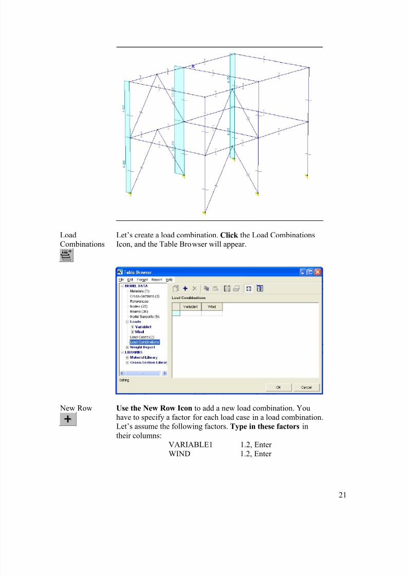
LoadCombinations
Let’s create a load combination. Click the Load CombinationsIcon, and the Table Browser will appear.
New Row Use the New Row Icon to add a new load combination. Youhave to specify a factor for each load case in a load combination.Let’s assume the following factors. Type in these factors intheir columns:
VARIABLE1 1.2, Enter WIND 1.2, Enter
8/3/2019 Model Cadru
http://slidepdf.com/reader/full/model-cadru 22/32
22
Accept the new load combination(s) by closing the TableBrowser with Ok .
Now the preprocessing part of the example is finished.
DisplayOptions Click the Display Options Icon , and uncheck the Node, Cross-Section Shape, Load boxes in the Symbols tab, andthe LoadValue box in the Labels tab.
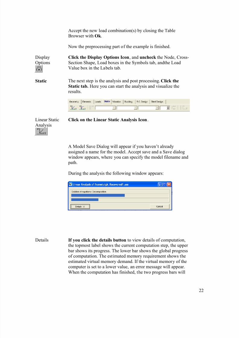
Static The next step is the analysis and post processing. Click theStatic tab. Here you can start the analysis and visualize theresults.
Linear StaticAnalysis
Click on the Linear Static Analysis Icon .
A Model Save Dialog will appear if you haven’t alreadyassigned a name for the model. Accept save and a Save dialogwindow appears, where you can specify the model filename and
path.
During the analysis the following window appears:
Details If you click the details button to view details of computation,the topmost label shows the current computation step, the upper
bar shows its progress. The lower bar shows the global progressof computation. The estimated memory requirement shows theestimated virtual memory demand. If the virtual memory of thecomputer is set to a lower value, an error message will appear.When the computation has finished, the two progress bars will
8/3/2019 Model Cadru
http://slidepdf.com/reader/full/model-cadru 23/32
23
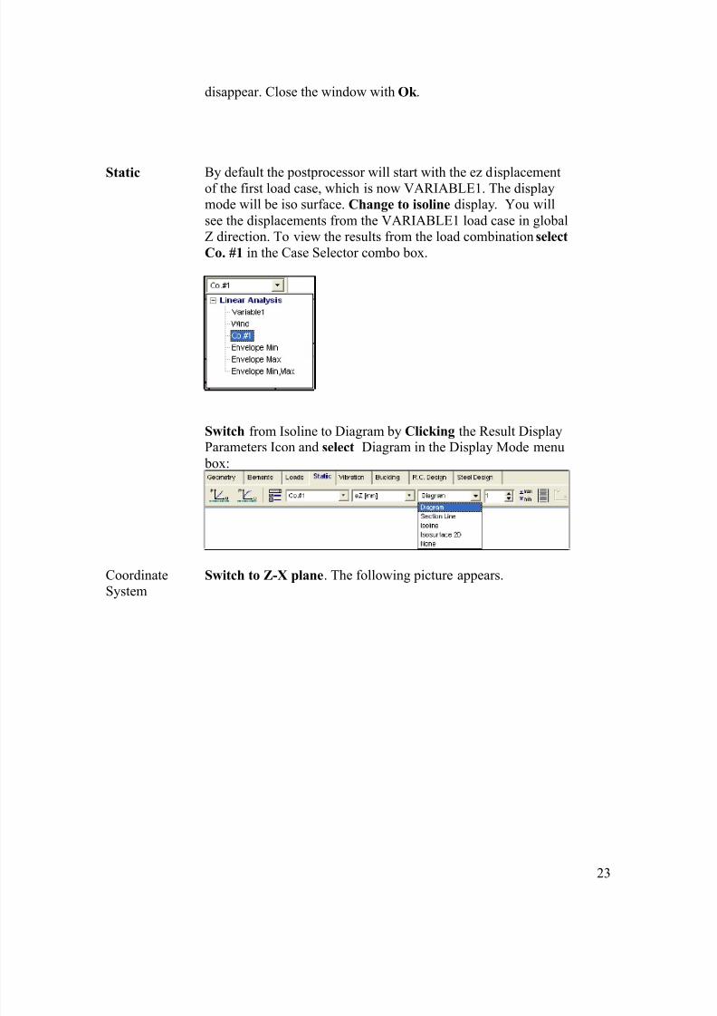
disappear. Close the window with Ok .
Static By default the postprocessor will start with the ez displacementof the first load case, which is now VARIABLE1. The displaymode will be iso surface. Change to isoline display. You willsee the displacements from the VARIABLE1 load case in globalZ direction. To view the results from the load combination selectCo. #1 in the Case Selector combo box.
Switch from Isoline to Diagram by Clicking the Result DisplayParameters Icon and select Diagram in the Display Mode menu
box:
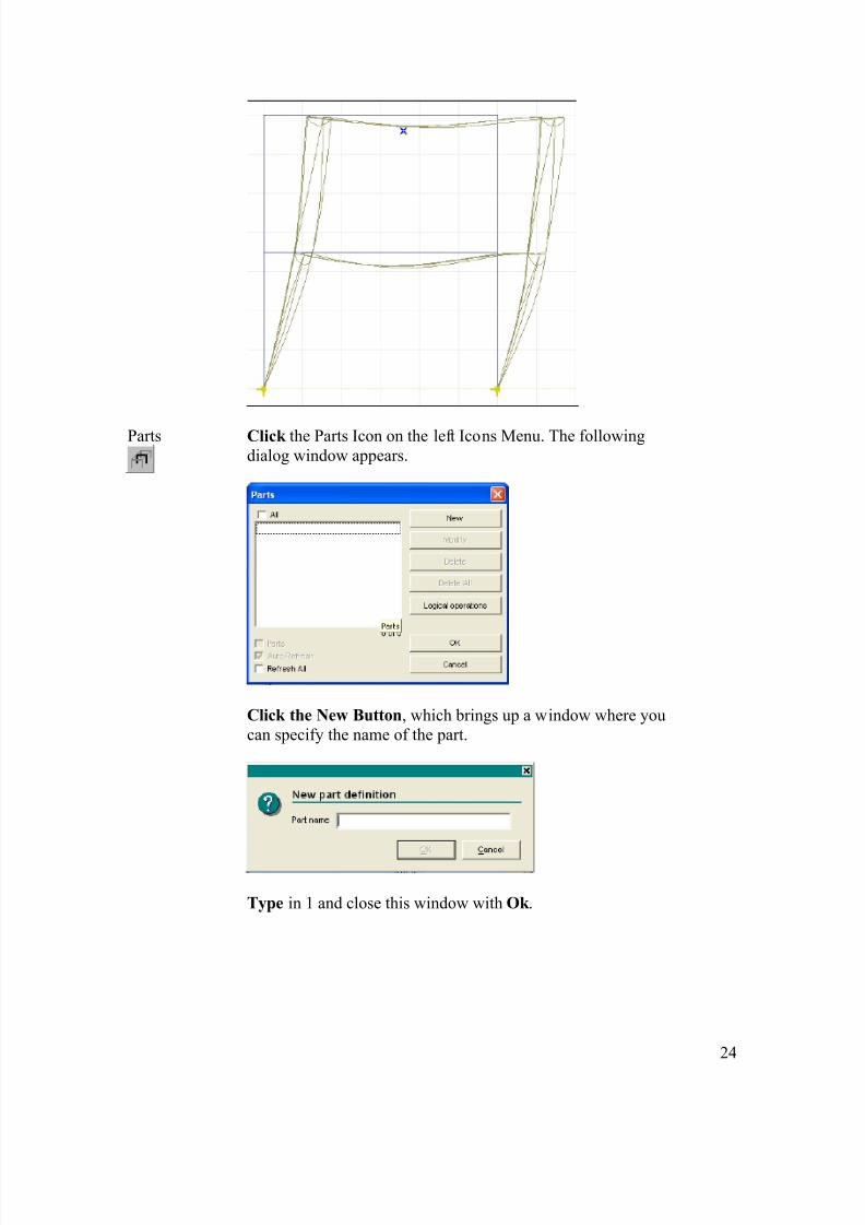
CoordinateSystem
Switch to Z-X plane . The following picture appears.
8/3/2019 Model Cadru
http://slidepdf.com/reader/full/model-cadru 24/32
24
Parts Click the Parts Icon on the left Icons Menu. The followingdialog window appears.
Click the New Button , which brings up a window where youcan specify the name of the part.
Type in 1 and close this window with Ok .

8/3/2019 Model Cadru
http://slidepdf.com/reader/full/model-cadru 25/32
25
You have to select the entities which will make up the partnamed 1. Select the right columns with a selection windowaccording to the following picture.
Finish the selection with Ok . The dialog window will reappear as in the picture below.
Close the dialog window with Ok , and part 1 will be accepted.
CoordinateSystem
Switch to Z-Y plane .
8/3/2019 Model Cadru
http://slidepdf.com/reader/full/model-cadru 26/32
26
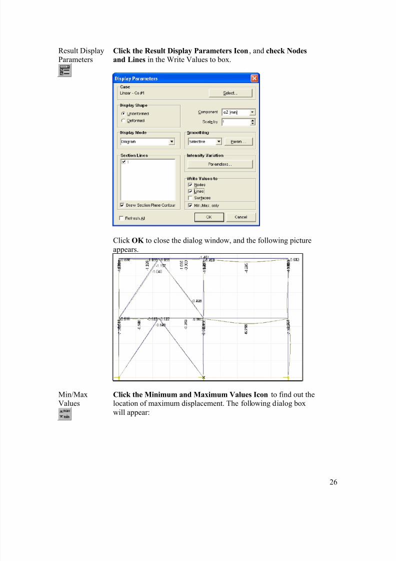
Result DisplayParameters
Click the Result Display Parameters Icon , and check Nodesand Lines in the Write Values to box.
Click OK to close the dialog window, and the following pictureappears.
Min/MaxValues
Click the Minimum and Maximum Values Icon to find out thelocation of maximum displacement. The following dialog boxwill appear:

8/3/2019 Model Cadru
http://slidepdf.com/reader/full/model-cadru 27/32
27
Here you can select one displacement component. Leave it on ezand click Ok . First the location and value of the negativeminimum displacement appears.
Click Ok , and the location and value of positive maximumdisplacement will appear.

8/3/2019 Model Cadru
http://slidepdf.com/reader/full/model-cadru 28/32
28
Select from the Result Component combo box Nx from theBeam Internal Forces. Click the Result Display ParametersIcon, Change display to section line.
The Nx force diagram will appear.
View the My moment diagram in a similar way.
8/3/2019 Model Cadru
http://slidepdf.com/reader/full/model-cadru 29/32
29
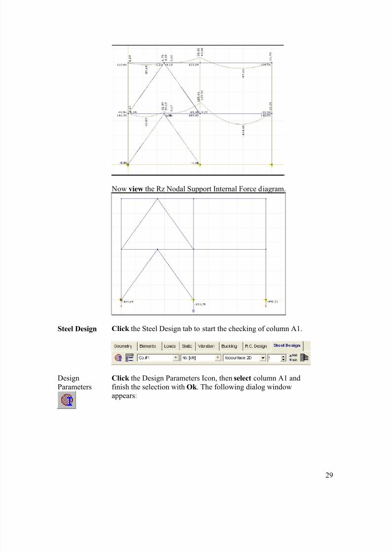
Now view the Rz Nodal Support Internal Force diagram.
Steel Design Click the Steel Design tab to start the checking of column A1.
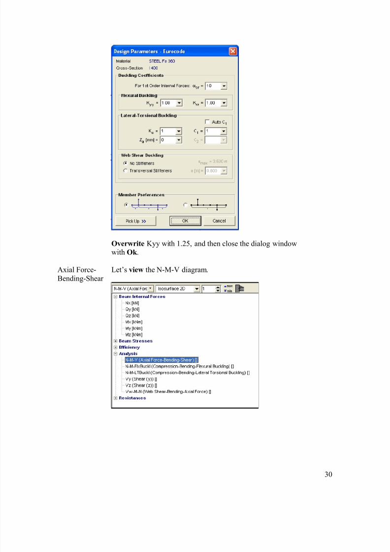
Design
Parameters
Click the Design Parameters Icon, then select column A1 and
finish the selection with Ok . The following dialog windowappears:
8/3/2019 Model Cadru
http://slidepdf.com/reader/full/model-cadru 30/32
30
Overwrite Kyy with 1.25, and then close the dialog windowwith Ok .
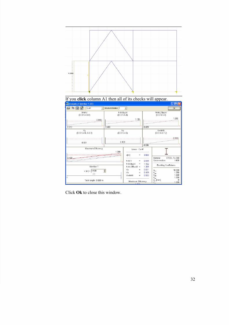
Axial Force-Bending-Shear
Let’s view the N-M-V diagram.

8/3/2019 Model Cadru
http://slidepdf.com/reader/full/model-cadru 31/32
31
The following picture appears:
Buckling Now view the N-M-Flx Buckling diagram:
Choose the efficiency diagram. The following picture appears:
8/3/2019 Model Cadru
http://slidepdf.com/reader/full/model-cadru 32/32
If you click column A1 then all of its checks will appear.
Click Ok to close this window.


![Model Acord-cadru (Lot I, Lot II)[Semnat] (1)](https://static.fdocumente.com/doc/165x107/55cf91ed550346f57b91dd6c/model-acord-cadru-lot-i-lot-iisemnat-1.jpg)