TEZĂ DE DOCTORAT - upb.ro · 3.1. ORGANIC RANKINE CYCLE ADVANTAGES AND ... Kalina cycle, Stirling...
23
_________________________________________________________________________________________________________________ FONDUL SOCIAL EUROPEAN Investeşte în oameni Programul Operaţional Sectorial pentru Dezvoltarea Resurselor Umane 2007 – 2013 Axa prioritară 1: Educaţia şi formarea profesională în sprijinul creşterii economice şi dezvoltării societăţii bazate pe cunoaştere Domeniul major de intervenţie 1.5: Programe doctorale şi postdoctorale în sprijinul cercetării Promovarea ştiinţei şi calităţii în cercetare prin burse doctorale (PROSCIENCE) POSDRU/187/1.5/S/155536 ___________________________________________________________________________________________________________________ UNIVERSITATEA POLITEHNICA DIN BUCUREŞTI Facultatea de Inginerie Mecanică şi Mecatronică Departamentul Termotehnică, Motoare, Echipamente Termice şi Frigorifice TEZĂ DE DOCTORAT Recuperarea căldurii din gazele de evacuare ale unui motor diesel folosind ciclul Rankine organic Diesel engine exhaust heat recovery using Organic Rankine Cycle Autor: Ing. Mădălina Irina GHILVACS Conducător de doctorat: Prof. dr. ing. Tudor PRISECARU COMISIA DE DOCTORAT Preşedinte Prof. dr. ing. Mariana ȘTEFĂNESCU de la UP Bucureşti Conducător de doctorat Prof. dr. ing. Tudor PRISECARU de la UP Bucureşti Referent Prof. dr. ing. Bogdan HORBANIUC de la UTGA Iași Referent Prof. dr. ing. Mugur BĂLAN de la UT Cluj-Napoca Referent Prof. dr. ing. Dorin STANCIU de la UP Bucureşti BUCUREŞTI 2018
Transcript of TEZĂ DE DOCTORAT - upb.ro · 3.1. ORGANIC RANKINE CYCLE ADVANTAGES AND ... Kalina cycle, Stirling...
_________________________________________________________________________________________________________________
FONDUL SOCIAL EUROPEAN
Investeşte în oameni
Programul Operaţional Sectorial pentru Dezvoltarea Resurselor Umane 2007 – 2013
Axa prioritară 1: Educaţia şi formarea profesională în sprijinul creşterii economice şi dezvoltării societăţii bazate pe cunoaştere
Domeniul major de intervenţie 1.5: Programe doctorale şi postdoctorale în sprijinul cercetării
Promovarea ştiinţei şi calităţii în cercetare prin burse doctorale (PROSCIENCE)
POSDRU/187/1.5/S/155536
___________________________________________________________________________________________________________________
UNIVERSITATEA POLITEHNICA DIN BUCUREŞTI
Facultatea de Inginerie Mecanică şi Mecatronică
Departamentul Termotehnică, Motoare, Echipamente Termice şi Frigorifice
TEZĂ DE DOCTORAT
Recuperarea căldurii din gazele de evacuare ale unui motor diesel folosind
ciclul Rankine organic
Diesel engine exhaust heat recovery using Organic Rankine Cycle
Autor: Ing. Mădălina Irina GHILVACS
Conducător de doctorat: Prof. dr. ing. Tudor PRISECARU
COMISIA DE DOCTORAT
Preşedinte Prof. dr. ing. Mariana ȘTEFĂNESCU de la UP Bucureşti
Conducător de doctorat Prof. dr. ing. Tudor PRISECARU de la UP Bucureşti
Referent Prof. dr. ing. Bogdan HORBANIUC de la UTGA Iași
Referent Prof. dr. ing. Mugur BĂLAN de la UT Cluj-Napoca
Referent Prof. dr. ing. Dorin STANCIU de la UP Bucureşti
BUCUREŞTI
2018
Diesel engine exhaust heat recovery using Organic Rankine Cycle
2
Content
List of figures iv
List of tables vii
Terminology viii
INTRODUCTION
CHAPTER 1
INTERNAL COMBUSTION ENGINES WASTE HEAT EVALUATION 3
4.1. ENERGY BALANCE OF INTERNAL COMBUSTION
ENGINES………………………………………………………………
5
4.2. ENGINE‘S TECHNICAL CHARACTERISTICS…………………….. 7
4.3. EXPERIMENTAL RESULTS…………………………………………. 8
CHAPTER 2
WASTE HEAT RECOVERY TECHNOLOGIES FOR AUTOMOTIVE
APPLICATIONS
16
CHAPTER 3
ORGANIC RANKINE CYCLE 19
3.1. ORGANIC RANKINE CYCLE ADVANTAGES AND
DISADVANTAGES …………………………………………………...
19
3.2. ORC CONFIGURATIONS FOR INTERNAL COMBUSTION
ENGINE WASTE HEAT RECOVERY………………………………..
20
3.3. SELECTIVE EVALUATION OF RESEARCH FOR RECOVERING
THE RESIDUAL HEAT IN AUTOMOTIVE APPLICATIONS ……..
22
Diesel engine exhaust heat recovery using Organic Rankine Cycle
3
CHAPTER 4
PERFORMANCE EVALUATION OF VEHICLES EXHAUST HEAT
RECUPERATION USING ORGANIC RANKINE CYCLE
25
4.1. MOTIVATION………………………………………………………… 25
4.2. SYSTEM DESCRIPTION …………………………………………….. 25
4.2.1. Presentation of the engine used………………………………..... 26
4.2.2. Prezentation of the Organic Rankine Cycle……………………. 27
4.3. STEADY STATE MATHEMATICAL MODELING FOR ORC …….. 30
4.3.1. Flow Chart of the program……………………………………… 31
4.3.2. Working Fluids for Organic Rankine Cycle……………..…….. 31
4.3.3. Processes in the ORC system …………………………………… 32
4.3.4. Calculation design of heat exchangers…………………………. 34
4.3.4.1. Thermal balance equations in heat exchangers……………….. 34
4.3.4.2. Logarithmic mean temperature difference……………………. 35
4.3.4.3. Coeficientului global de transfer de căldură…………………. 36
4.3.4.4. Overall heat transfer coefficient……………………………… 38
4.4. IMPLEMENTATION AND VALIDATION OF THE
MATHEMATICAL MODEL
39
4.5. RESULTS……………………………………………………………… 40
4.5.1. Choosing the optimal working fluid for ORC system…………. 40
4.5.2. Choosing the heat exchangers…………………………………… 42
4.5.3. The results obtained for the considered case…………………… 46
4.5.4. The results obtained for the entire operating range of the
engine ……………………………………………………………..
46
CHAPTER 5
EXPERIMENTAL SETUP OF THE ORGANIC RANKINE CYCLE –
INTERNAL COMBUSTION ENGINE SYSTEM
56
5.1 OBJECTIVE…………………………………………………………… 56
5.2 STAND DESCRIPTION……………………………………………… 56
5.2.1 The evaporator…………………………………………………… 58
5.2.2 The condenser……………………………………………………. 59
5.2.3 The expander…………………………………………………….. 60
5.2.4 The pump………………………………………………………… 61
5.3 DESCRIPTION OF DATA ACQUISITION SYSTEM……………….. 62
5.4 DESCRPTION OF THE CONTROL PANEL………………………… 63
Diesel engine exhaust heat recovery using Organic Rankine Cycle
4
5.5 SYSTEM ADVANTAGES……………………………………….......... 66
CHAPTER 6
UNSTAEADY STATE MODELING OF ORGANIC RANKINE CYCLE
EVAPORATOR
68
6.1. EVALUATION OF THE EXHAUST WASTE HEAT FOR AN
PASSENGER CAR AT TRANSIENT OPERATION.................................
68
6.2. PRESENTATION OF ORGANIC RANKINE CYCLE.............................. 71
6.3. MATHEMATICAL MODELING FOR ORC SYSTEM............................ 72
6.3.1. Steady state………………………………………………………. 72
6.3.2. Unsteady state……………………………………………………. 72
6.3.2.1. Energy balance equations…………………………………….. 74
6.3.2.2. The Runge-Kutta method of the 4th order…………………….. 76
6.3.2.3. Working fluids properties…………………………………….. 79
6.4. MODEL VALIDATION ............................................................................. 84
6.5. RESULTS.................................................................................................... 86
CONCLUSIONS
C1. GENERAL CONCLUSIONS 89
C2. ORIGINAL CONTRIBUTIONS 92
C3. SUGGESTIONS FOR FUTURE WORK 92
References 94
ANNEXES
A1. STEADY STATE MATHEMATICAL MODELING 98
A2. UN STEADY STATE MATHEMATICAL MODELING
A3. LIST OF PUBLICATIONS
108
113
Diesel engine exhaust heat recovery using Organic Rankine Cycle
6
Summary
In recent years, there has been a great deal of waste heat energy being released into the
environment, such as exhaust gases from turbines and engines and waste heat from industrial
plants, which lead to serious environmental pollution. In addition, there are also abundant
geothermal resources and solar energy available in the world. These heat sources are
classified as low grade heat sources. Therefore, more and more attention has been paid to the
utilization of low grade waste heat nowadays for its potential in reducing fossil fuel
consumption and alleviating environmental problems.
Since conventional steam power cycles cannot give a better performance to recover
low grade waste heat, the organic Rankine cycle (ORC) is proposed to recover low grade
waste heat. There are several advantages in using an ORC to recover low grade waste heat,
including economical utilization of energy resources, smaller systems and reduced emissions
of CO, CO2, NOx and other atmospheric pollutants. The main advantage of the ORC is its
superior performance in recovering waste heat with a low temperature.
Besides the ORC, researchers have proposed various thermodynamic cycles, such as
Kalina cycle, Stirling cycle, and Ericsson cycle, to convert this low-grade heat sources into
electricity. Although there is more power output for the same heat input with Kalina cycles
compared to ORCs, the ORC syetem is much less complex and needs less maintenance.
The Organic Rankine Cycle is a cost efficient and proven method of converting low
temperature waste heat to mechanical and/or electrical energy. This opens up the possibility to
exploit low-grade heat that otherwise would be wasted. It can play an important role to
improve the thermal efficiency of internal combustion engines.
A thermal engine converts 30 % of the fuel energy into mechanical shaft work; the rest
of energy is wasted through the cooling liquid and the exhaust gases. Thus, it would be
possible to convert this wasted heat in order to improve the engine overall efficiency and
reduce the fuel consumption of the vehicle.
This paper describes the performance of exhaust heat recovery using an ORC in a
passenger car.
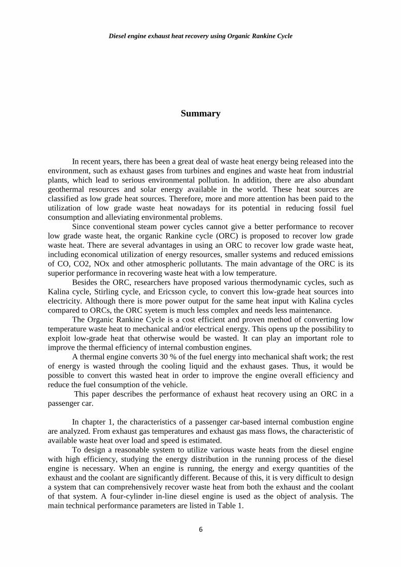
In chapter 1, the characteristics of a passenger car-based internal combustion engine
are analyzed. From exhaust gas temperatures and exhaust gas mass flows, the characteristic of
available waste heat over load and speed is estimated.
To design a reasonable system to utilize various waste heats from the diesel engine
with high efficiency, studying the energy distribution in the running process of the diesel
engine is necessary. When an engine is running, the energy and exergy quantities of the
exhaust and the coolant are significantly different. Because of this, it is very difficult to design
a system that can comprehensively recover waste heat from both the exhaust and the coolant
of that system. A four-cylinder in-line diesel engine is used as the object of analysis. The
main technical performance parameters are listed in Table 1.
Diesel engine exhaust heat recovery using Organic Rankine Cycle
7
When a vehicle is running, the engine speed and load can vary through a wide range.
Therefore, the engine performance test was conducted in an engine test cell in order to obtain
the thermodynamic parameters of the exhaust and coolant systems overall possible engine
operating regions as defined by the engine speed and output torque. For our measurements,
the minimal and maximal engine speeds were set to 1000 rot/min and 4500 rot/min,
respectively. The intermediate speeds were selected using a step increment of 250 rot/min,
starting from the minimum engine speed. At each selected engine speed, different load values
were selected, ranging from a 100% load to a minimal stable load value. The values for the
output torque, the output power, the engine speed, the mass flow rate of the intake air, the
injected fuel quantity, the exhaust gas temperature, and the coolant temperatures at the outlet
of the engine’s water jacket were all recorded for each load and speed configuration.
Table 1: The main technical performance parameters of the diesel engine [3]
Items Parameters Units
Model Diesel [-]
Cylinder number 4 [-]
Stroke and cylinder bore 88.3x75 [mm]
Displacement 1560 [cm3]
Compression ratio 18:1 [-]
Air intake type Turbocharged and Intercooled [-]
Fuel injection system High pressure common rail [-]
Rated power 80 [kW]
Rated speed 4000 [rpm]
Maximum torque 240 [Nm]
Speed at maximum torque 1800 [rpm]
The distribution of fuel energy released by combustion under a certain operating
condition of the diesel engine is depicted using the first law of thermodynamics, which is:
restgrcb QQQPQ
(1)
Where: cbQ is the heat flux received through fuel combustion; P is the amount of
mechanical power produced; rQ is the heat flux rejected through the water cooling system;
gQ is the heat rejected through the exhaust gases and restQ is the heat flux rejected through
radiation and incomplete combustion that cannot be directly determined in this stage.
The heat flux received through fuel combustion can be computed as:
icbcbcb HmQ (2)
Where ]/[ skgmcb is the fuel mass flow rate and ]/[4200 kgkJHicb is the inferior
fuel heat value. The inferior fuel heat value is considered from data available in literature
[5,6].
Next, the heat flux rejected through the water cooling system can be computed as
follows:
)( iewwr ttcmQ (3)
In eq. (3) ]/[ skgmw is the water mass flow rate; ]/[186.4 kgKkJcw is the water
heat capacity; ][ Ct e and ][ Ct i are water temperatures at engine outlet and inlet,
respectively.
Diesel engine exhaust heat recovery using Organic Rankine Cycle
8
The heat flux ][kWQg rejected through exhaust gases is computed as:
airegg QQQ (4)
Where, ][kWQeg is the total heat flux available in exhaust gases and ][kWQair
is the
heat flux due to the fresh load.
The quantity of waste heat contained in exhaust gas is a function of both the
temperature and the mass flow rate of the exhaust gas:
gpggeg TcmQ (5)
In eq. (5) ]/[ skgmg is the exhaust gasses mass flow rate; ]/[ kgKkJc pg is the heat
capacity at constant pressure of exhaust gases and ][KTg is the temperature of exhaust gases.
Heat capacity of exhaust gases is considered from available data in literature according to
experimental data [5].
The heat flux due to the fresh load can be determined:
airpairairair TcmQ (6)
Where, ]/[ skgmair is the air mass flow rate ]/[013.1 kgKkJc pair is the heat
capacity at constant pressure and its value is considered from data available in literature [7]
and ][KTair is the measured ambient air temperature.
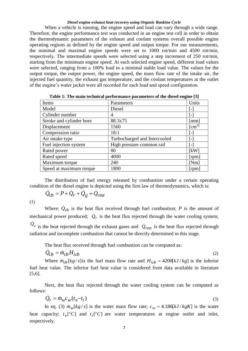
One common way to present the operating characteristics of an internal combustion
engine over its full load and speed range is to plot brake specific fuel consumption contours
on a graph of brake mean effective pressure (or engine torque) versus engine speed.
Fig. 1 Brake specific fuel consumption [g/kWh]
Diesel engine exhaust heat recovery using Organic Rankine Cycle
9
The measured engine performance map is displayed in Figure 1. The lowest brake
specific fuel consumption (b.s.f.c.) zone is situated at the high duty range between 1500
rot/min and 3000 rot/min and the minimum b.s.f.c. value is less than 210 g/kWh.
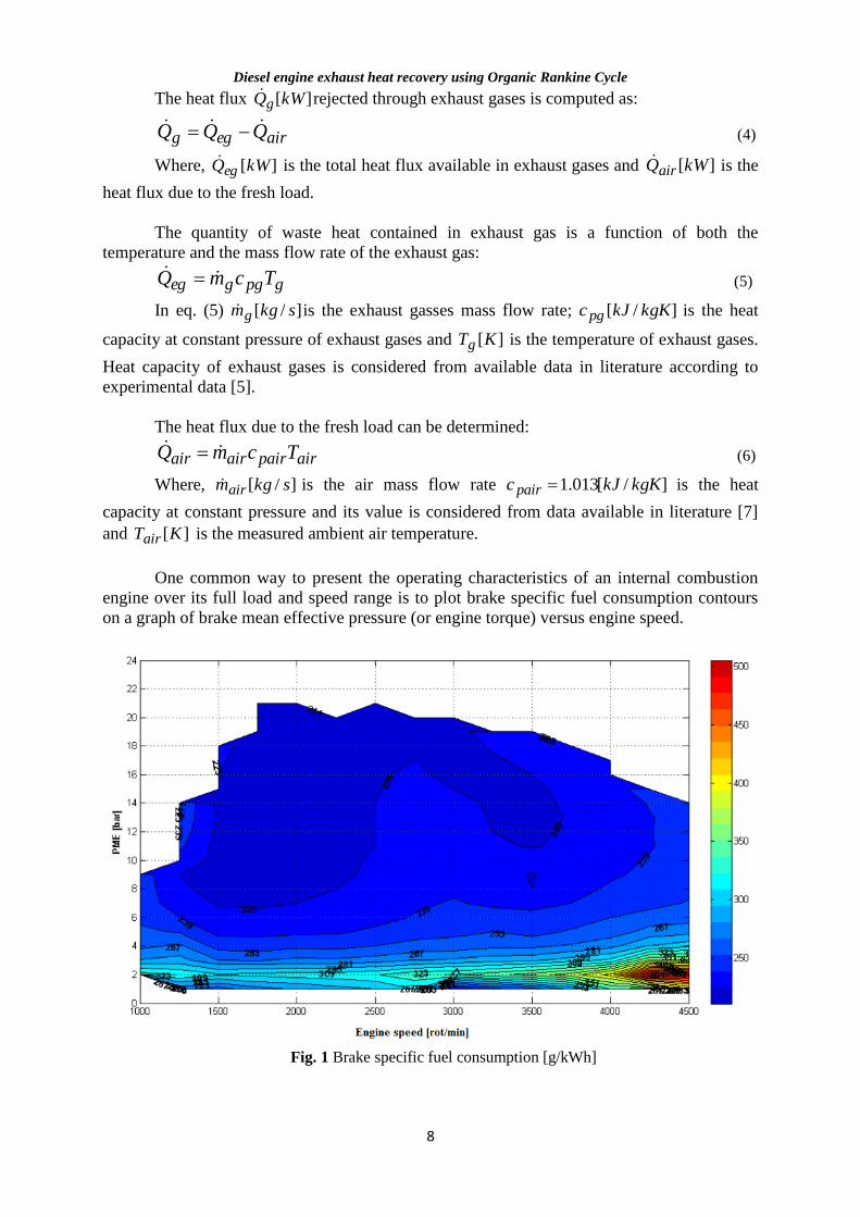
The effective thermal efficiency is defined as the ratio of the output torque at the
flywheel end to the fuel combustion energy, and the results are given in figure 2. The
effective thermal efficiency reaches a peak of greater than 40% in the low b.s.f.c. region.
Fig. 2 Engine effective thermal efficiency [%]
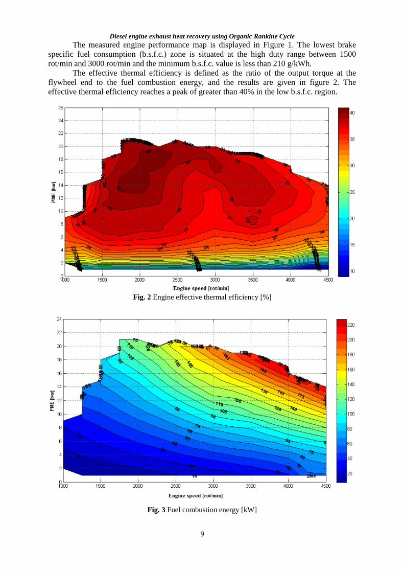
Fig. 3 Fuel combustion energy [kW]
Diesel engine exhaust heat recovery using Organic Rankine Cycle
10
The fuel energy released by combustion is shown in Figure 3. As the engine speed and
engine load increases, the fuel energy released by combustion increases gradually. Such
phenomenon is primarily caused by the increase in fuel consumption and intake air mass. The
combustion energy increases almost linearly with the engine output power, achieving 220 kW
at the rated power point. Note that the waste heat quantities of the exhaust and the coolant
vary in a similar fashion. The variation of the waste heat quantity carried by the coolant
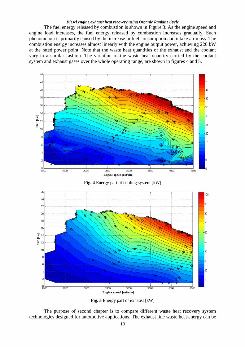
system and exhaust gases over the whole operating range, are shown in figures 4 and 5.
Fig. 4 Energy part of cooling system [kW]
Fig. 5 Energy part of exhaust [kW]
The purpose of second chapter is to compare different waste heat recovery system
technologies designed for automotive applications. The exhaust line waste heat energy can be
Diesel engine exhaust heat recovery using Organic Rankine Cycle
11
recovered by different means. The use of heat engines describing thermodynamic cycles such
as Rankine and Stirling engines is possible. A turbine similar to the one of car turbocharger
can also be used (turbocompounding) and coupled to an electric machine or to the
transmission line of the vehicle. Thermoelectricity is another alternative in which heat is
directly converted into electricity. Turbocompounding and Rankine cycle systems are the
most probable technologies to be soon integrated into passenger cars.
The third part reviews the history of internal combustion engine exhaust waste heat
recovery focusing on Organic Rankine Cycles since this thermodynamic cycle works well
with the medium-grade energy of the exhaust. Selection of the ORC arhitecture, expander
design and working fluid are the primary focus of the review, since they are regarded as
having the largest impact on system performance.
For each intended application, the additional expenditure and complexity associated
with incorporation of preheating with engine coolant waste heat or a recuperator above the
traditional Rankine cycle should be weighed against the resulting efficiency gains. No
configuration is optimal for every waste heat source; hence, a thermodynamic analysis
targeting the specific source must be conducted first.
Review of the literature demonstrates that selection of the working fluid and expander
has a significant influence on the efficiency of the WHR system. Most applications achieve
the highest ORC efficiencies using nearly isentropic and high critical temperature working
fluids. However, these criteria fail to address numerous practical design conditions, such as
operating pressures, component sizes, expander rotational speeds, expansion ratios, and
environmental concerns. Thus, the space available onboard mobile waste heat sources should
be determined prior to cycle design.
Results demonstrate a potential fuel economy improvement around 10% with modern
refrigerants and advancements in expander technology.
Chapter 4 describes the performance of exhaust heat recovery using an ORC in a
passenger car. The heat transfer properties are evaluated over the engine’s entire operating
region based on the measured data. Subsequently, a mathematical model of the plate heat
exchangers is created based on the specific ORC working conditions. The main aims of this
study are 1) the determination of the proper working fluid for ORC system, and 2) the
calculation of the heat transfer coefficient and the required surface area for the plate heat
exchangers (evaporator and condenser).
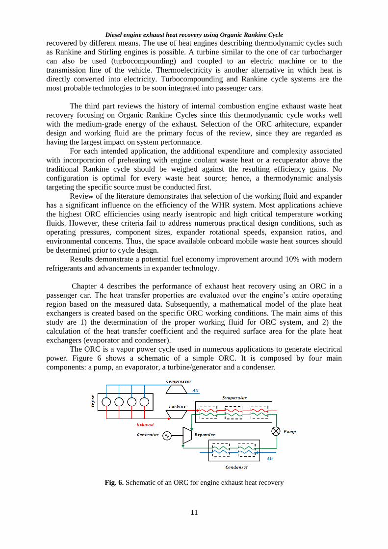
The ORC is a vapor power cycle used in numerous applications to generate electrical
power. Figure 6 shows a schematic of a simple ORC. It is composed by four main
components: a pump, an evaporator, a turbine/generator and a condenser.
Fig. 6. Schematic of an ORC for engine exhaust heat recovery
Diesel engine exhaust heat recovery using Organic Rankine Cycle
12
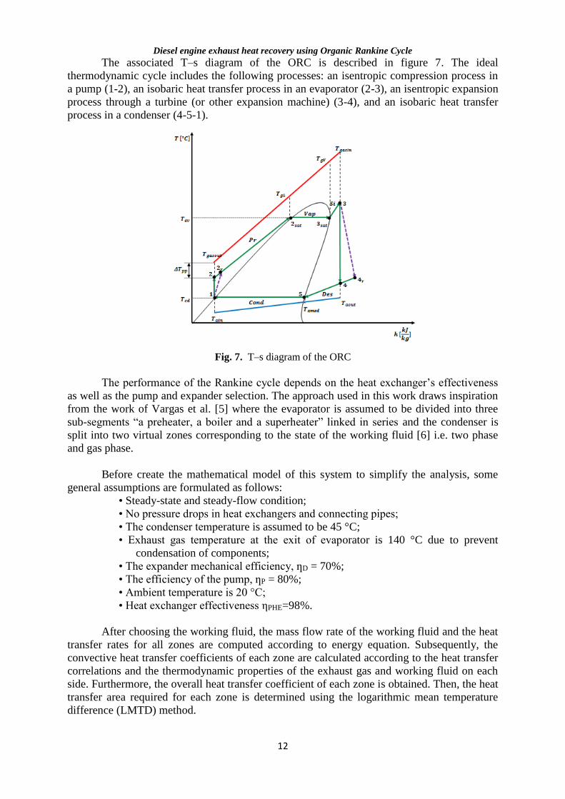
The associated T–s diagram of the ORC is described in figure 7. The ideal
thermodynamic cycle includes the following processes: an isentropic compression process in
a pump (1-2), an isobaric heat transfer process in an evaporator (2-3), an isentropic expansion
process through a turbine (or other expansion machine) (3-4), and an isobaric heat transfer
process in a condenser (4-5-1).
Fig. 7. T–s diagram of the ORC
The performance of the Rankine cycle depends on the heat exchanger’s effectiveness
as well as the pump and expander selection. The approach used in this work draws inspiration
from the work of Vargas et al. [5] where the evaporator is assumed to be divided into three
sub-segments “a preheater, a boiler and a superheater” linked in series and the condenser is
split into two virtual zones corresponding to the state of the working fluid [6] i.e. two phase
and gas phase.
Before create the mathematical model of this system to simplify the analysis, some
general assumptions are formulated as follows:
• Steady-state and steady-flow condition;
• No pressure drops in heat exchangers and connecting pipes;
• The condenser temperature is assumed to be 45 °C;
• Exhaust gas temperature at the exit of evaporator is 140 °C due to prevent
condensation of components;
• The expander mechanical efficiency, ƞD = 70%;
• The efficiency of the pump, ƞP = 80%;
• Ambient temperature is 20 °C;
• Heat exchanger effectiveness ηPHE=98%.
After choosing the working fluid, the mass flow rate of the working fluid and the heat
transfer rates for all zones are computed according to energy equation. Subsequently, the
convective heat transfer coefficients of each zone are calculated according to the heat transfer
correlations and the thermodynamic properties of the exhaust gas and working fluid on each
side. Furthermore, the overall heat transfer coefficient of each zone is obtained. Then, the heat
transfer area required for each zone is determined using the logarithmic mean temperature
difference (LMTD) method.
Diesel engine exhaust heat recovery using Organic Rankine Cycle
13
The total heat transfer rate between the counter flows in plate heat exchangers can be
calculated as follows:
)(22 gasoutgLPprgassatrefpr ttCmhhmQ (7)
)(23 gLgVPvapgassatsatrefvap ttCmhhmQ (8)
)( sin33 gLgaPsîgassatrefsî ttCmhhmQ (9)
)(54 amedaoutPaeraerrefdes ttCmhhmQ (10)
)(15 ainamedPaeraerrefcond ttCmhhmQ (11)
The logarithmic mean temperature difference can be obtained from the basic counter
flow LMTD equation:
min
max
minmax
lnT
T
TTTm
(12)
The phase-change heat transfer process generally has three stages in which the heat
transfer coefficient abides by different correction equations: liquid phase stage, two phase
stage and vapor phase stage. The heat transfer processes for single-phase flow and two-phase
flow are respectively discussed below.
In the single phase flow zone the Chisholm and Wanniarachchi correlation is
employed to calculate the Nusselt number for both hot fluid and cold fluid, which is a
function of the Reynolds, Prandtl numbers and the chevron angle of the plates [11]:
3/1583.0646.0
PrRe6
724.0
Nu (13)
In the two-phase region (condensation or evaporation), the fluid properties such as
density, specific heat, viscosity and thermal conductivity are observed to suffer from dramatic
variations with the quality variation of organic working fluid. For this reason the heat transfer
process in the two-phase region is divided into relatively small sections, with so slight
property variations in each section that constant properties can be assumed.
For condensation and evaporation process, in two-phase region, Nusselt number is
calculated using Yan and Lin’s correlation.
5.05.03.0
)(3/1
)( 1RePr926.1v
liiieqliR xxBoNu
(14)
3/14.0)()( PrRe118.4
lieqiCNu (15)
A program was created to evaluate the evaporator and condenser performance in
Engineering Equation Solver (EES) according to the established mathematical model.
The first step in the design procedure of an ORC system is the selection of the organic
fluid. To select an appropriate working fluid to achieve the maximum thermal efficiency and
exergy efficiency in various working conditions, a preliminary selection was conducted. In
addition, material compatibility, flammability, toxicity, global warming potential (GWP),
Diesel engine exhaust heat recovery using Organic Rankine Cycle
14
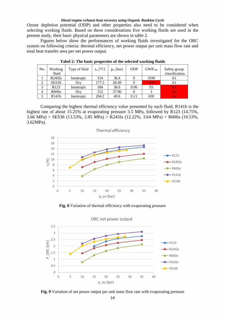
Ozone depletion potential (ODP) and other properties also need to be considered when
selecting working fluids. Based on these considerations five working fluids are used in the
present study, their basic physical parameters are shown in table 2.
Figures below show the performances of working fluids investigated for the ORC
system on following criteria: thermal efficiency, net power output per unit mass flow rate and
total heat transfer area per net power output.
Tabel 2: The basic properties of the selected working fluids
No.
Working
fluid
Type of fluid tcr [°C] pcr [bar] ODP GWP100 Safety group
classification
1 R245fa Isentropic 154 36.4 0 1030 A1
2 SES36 Dry 177.5 28.49 0 3126 A1
3 R123 Isentropic 184 36.6 0.06 93 B1
4 R600a Dry 152 37.96 0 3 A3
5 R141b Isentropic 204.2 40.6 0.11 630 A2
Comparing the highest thermal efficiency value presented by each fluid, R141b is the
highest one of about 15.25% at evaporating pressure 3.5 MPa, followed by R123 (14.75%,
3.66 MPa) > SES36 (13.53%, 2.85 MPa) > R245fa (12.22%, 3.64 MPa) > R600a (10.53%,
3.62MPa).
Fig. 8 Variation of thermal efficiency with evaporating pressure
Fig. 9 Variation of net power output per unit mass flow rate with evaporating pressure
0
2
4
6
8
10
12
14
16
18
0 5 10 15 20 25 30 35 40
ɳ [
%]
p_ev [bar]
Thermal efficiency
R123
R245fa
R600a
R141b
SES36
0
0.5
1
1.5
2
2.5
3
3.5
0 5 10 15 20 25 30 35 40
P_O
RC
[kW
]
p_ev [bar]
ORC net power output
R123
R245fa
R600a
R141b
SES36
Diesel engine exhaust heat recovery using Organic Rankine Cycle
15
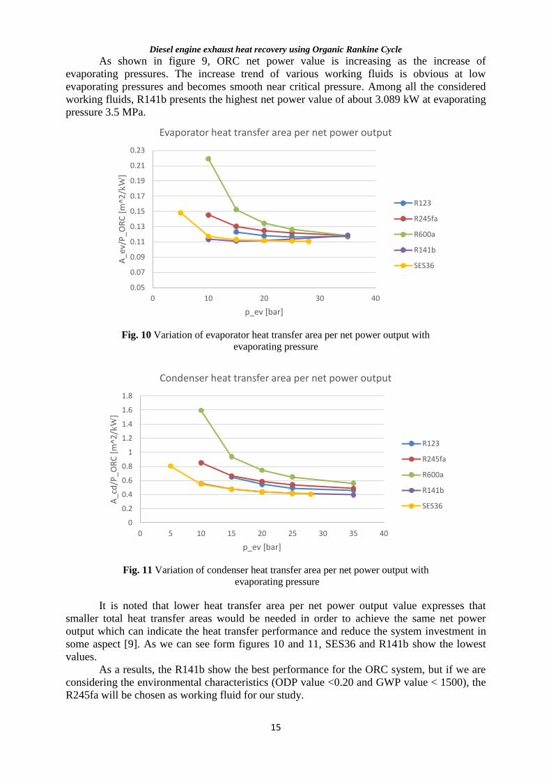
As shown in figure 9, ORC net power value is increasing as the increase of
evaporating pressures. The increase trend of various working fluids is obvious at low
evaporating pressures and becomes smooth near critical pressure. Among all the considered
working fluids, R141b presents the highest net power value of about 3.089 kW at evaporating
pressure 3.5 MPa.
Fig. 10 Variation of evaporator heat transfer area per net power output with
evaporating pressure
Fig. 11 Variation of condenser heat transfer area per net power output with
evaporating pressure
It is noted that lower heat transfer area per net power output value expresses that
smaller total heat transfer areas would be needed in order to achieve the same net power
output which can indicate the heat transfer performance and reduce the system investment in
some aspect [9]. As we can see form figures 10 and 11, SES36 and R141b show the lowest
values.
As a results, the R141b show the best performance for the ORC system, but if we are
considering the environmental characteristics (ODP value <0.20 and GWP value < 1500), the
R245fa will be chosen as working fluid for our study.
0.05
0.07
0.09
0.11
0.13
0.15
0.17
0.19
0.21
0.23
0 10 20 30 40
A_e
v/P
_OR
C [
m^2
/kW
]
p_ev [bar]
Evaporator heat transfer area per net power output
R123
R245fa
R600a
R141b
SES36
0
0.2
0.4
0.6
0.8
1
1.2
1.4
1.6
1.8
0 5 10 15 20 25 30 35 40
A_c
d/P
_OR
C [
m^2
/kW
]
p_ev [bar]
Condenser heat transfer area per net power output
R123
R245fa
R600a
R141b
SES36
Diesel engine exhaust heat recovery using Organic Rankine Cycle
16
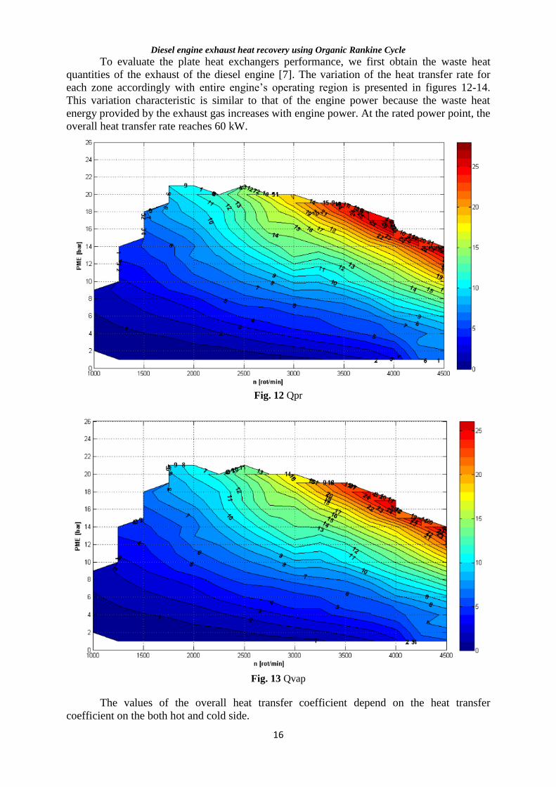
To evaluate the plate heat exchangers performance, we first obtain the waste heat
quantities of the exhaust of the diesel engine [7]. The variation of the heat transfer rate for
each zone accordingly with entire engine’s operating region is presented in figures 12-14.
This variation characteristic is similar to that of the engine power because the waste heat
energy provided by the exhaust gas increases with engine power. At the rated power point, the
overall heat transfer rate reaches 60 kW.
Fig. 12 Qpr
Fig. 13 Qvap
The values of the overall heat transfer coefficient depend on the heat transfer
coefficient on the both hot and cold side.
Diesel engine exhaust heat recovery using Organic Rankine Cycle
17
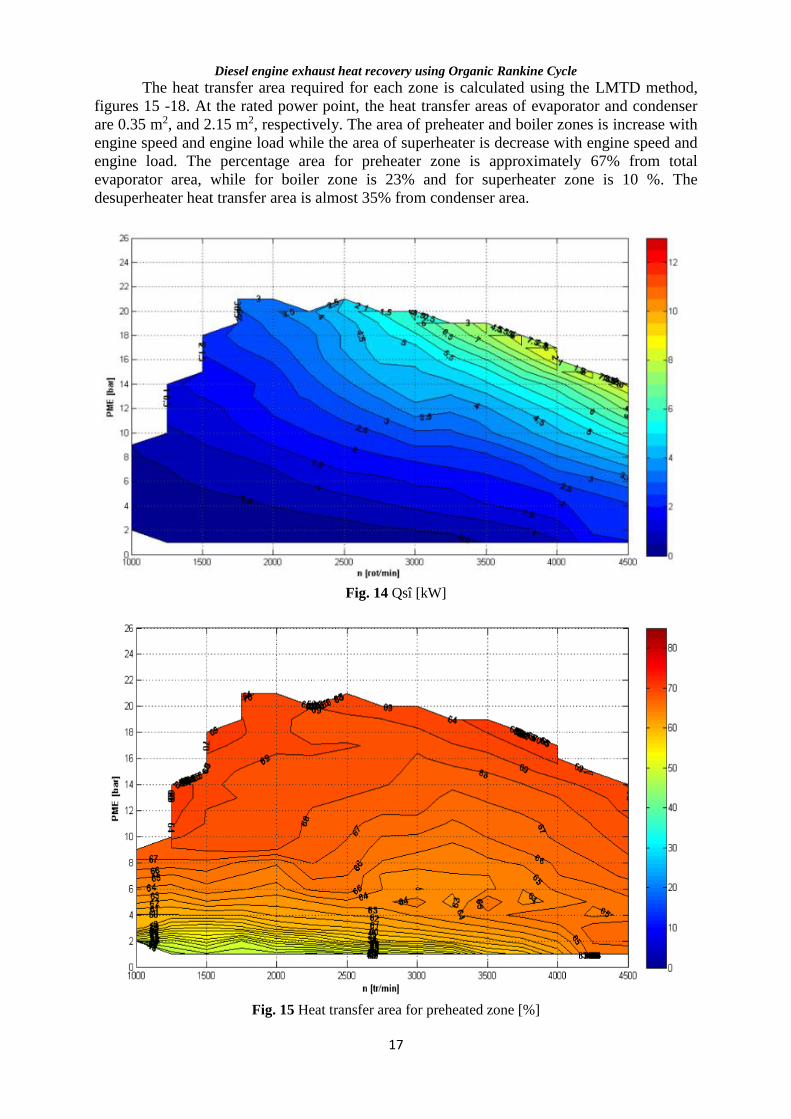
The heat transfer area required for each zone is calculated using the LMTD method,
figures 15 -18. At the rated power point, the heat transfer areas of evaporator and condenser
are 0.35 m2, and 2.15 m2, respectively. The area of preheater and boiler zones is increase with
engine speed and engine load while the area of superheater is decrease with engine speed and
engine load. The percentage area for preheater zone is approximately 67% from total
evaporator area, while for boiler zone is 23% and for superheater zone is 10 %. The
desuperheater heat transfer area is almost 35% from condenser area.
Fig. 14 Qsî [kW]
Fig. 15 Heat transfer area for preheated zone [%]
Diesel engine exhaust heat recovery using Organic Rankine Cycle
18
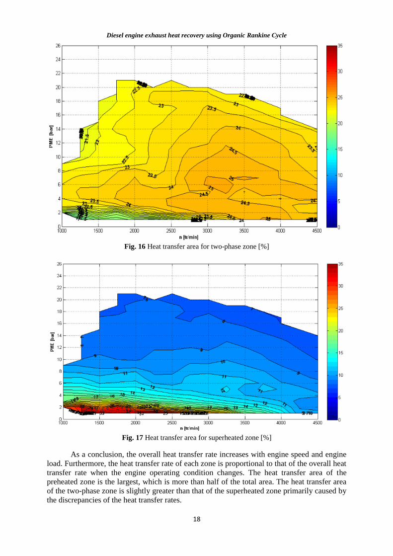
Fig. 16 Heat transfer area for two-phase zone [%]
Fig. 17 Heat transfer area for superheated zone [%]
As a conclusion, the overall heat transfer rate increases with engine speed and engine
load. Furthermore, the heat transfer rate of each zone is proportional to that of the overall heat
transfer rate when the engine operating condition changes. The heat transfer area of the
preheated zone is the largest, which is more than half of the total area. The heat transfer area
of the two-phase zone is slightly greater than that of the superheated zone primarily caused by
the discrepancies of the heat transfer rates.
Diesel engine exhaust heat recovery using Organic Rankine Cycle
19
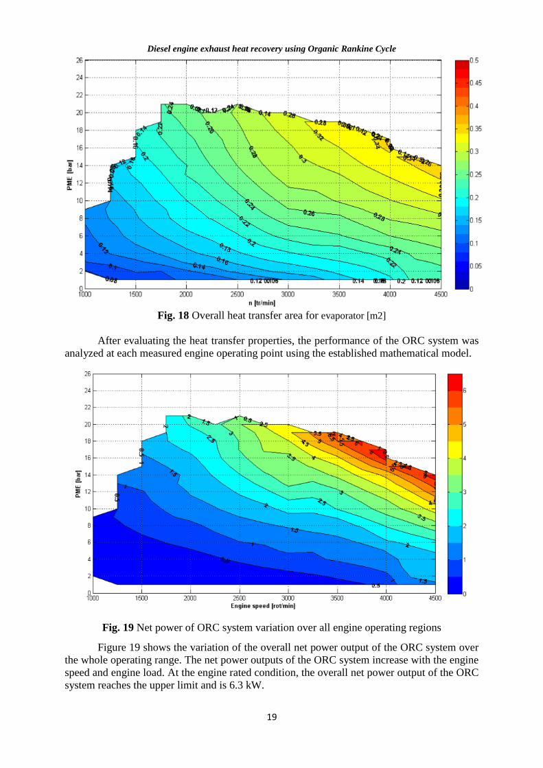
Fig. 18 Overall heat transfer area for evaporator [m2]
After evaluating the heat transfer properties, the performance of the ORC system was
analyzed at each measured engine operating point using the established mathematical model.
Fig. 19 Net power of ORC system variation over all engine operating regions
Figure 19 shows the variation of the overall net power output of the ORC system over
the whole operating range. The net power outputs of the ORC system increase with the engine
speed and engine load. At the engine rated condition, the overall net power output of the ORC
system reaches the upper limit and is 6.3 kW.
Diesel engine exhaust heat recovery using Organic Rankine Cycle
20
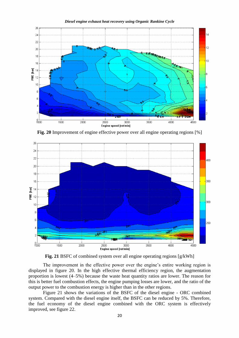
Fig. 20 Improvement of engine effective power over all engine operating regions [%]
Fig. 21 BSFC of combined system over all engine operating regions [g/kWh]
The improvement in the effective power over the engine’s entire working region is
displayed in figure 20. In the high effective thermal efficiency region, the augmentation
proportion is lowest (4–5%) because the waste heat quantity ratios are lower. The reason for
this is better fuel combustion effects, the engine pumping losses are lower, and the ratio of the
output power to the combustion energy is higher than in the other regions.
Figure 21 shows the variations of the BSFC of the diesel engine - ORC combined
system. Compared with the diesel engine itself, the BSFC can be reduced by 5%. Therefore,
the fuel economy of the diesel engine combined with the ORC system is effectively
improved, see figure 22.
Diesel engine exhaust heat recovery using Organic Rankine Cycle
21
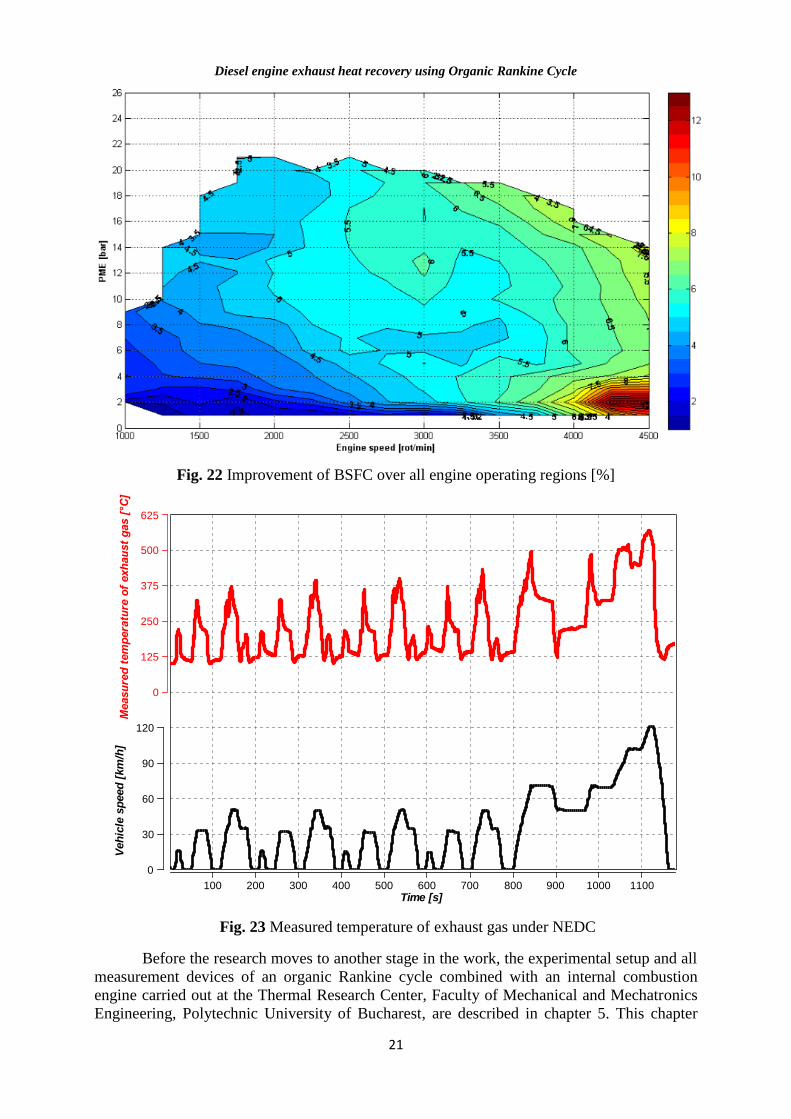
Fig. 22 Improvement of BSFC over all engine operating regions [%]
Fig. 23 Measured temperature of exhaust gas under NEDC
Before the research moves to another stage in the work, the experimental setup and all
measurement devices of an organic Rankine cycle combined with an internal combustion
engine carried out at the Thermal Research Center, Faculty of Mechanical and Mechatronics
Engineering, Polytechnic University of Bucharest, are described in chapter 5. This chapter
100 200 300 400 500 600 700 800 900 1000 1100Time [s]
Veh
icle
sp
eed
[km
/h]
0
30
60
90
120
Measu
red
tem
pera
ture
of
exh
au
st
gas [
°C]
0
125
250
375
500
625
Diesel engine exhaust heat recovery using Organic Rankine Cycle
22
contains a number of tables and figures that describe the experimental setup. The
experimental setup is a key element in fulfilling the objectives of the PhD Thesis.
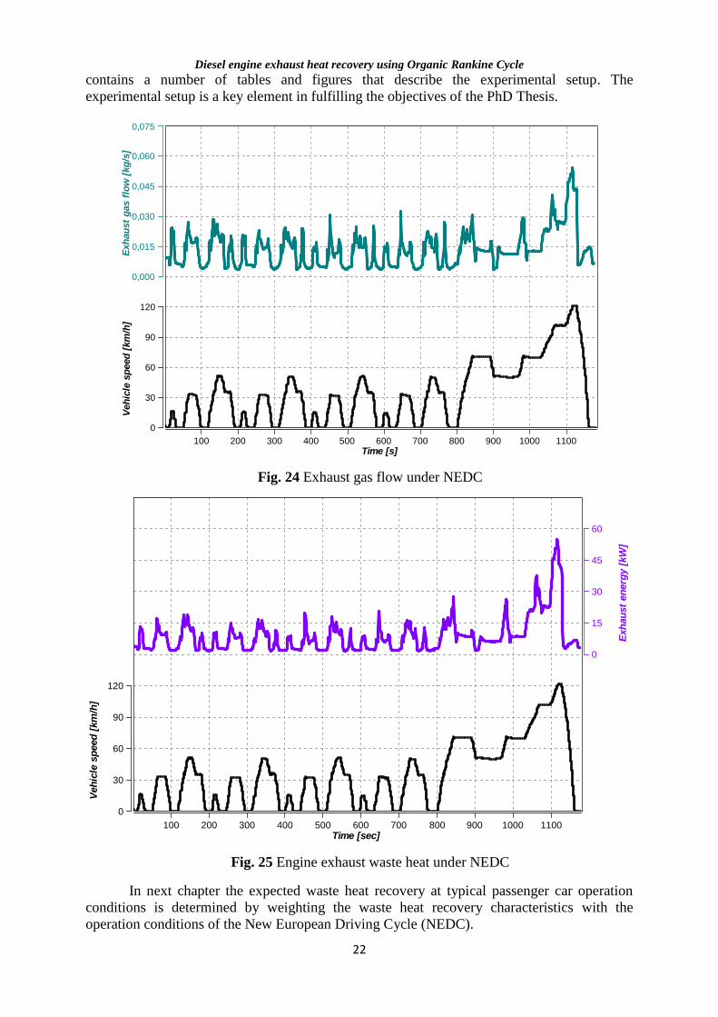
Fig. 24 Exhaust gas flow under NEDC
Fig. 25 Engine exhaust waste heat under NEDC
In next chapter the expected waste heat recovery at typical passenger car operation
conditions is determined by weighting the waste heat recovery characteristics with the
operation conditions of the New European Driving Cycle (NEDC).
100 200 300 400 500 600 700 800 900 1000 1100Time [s]
Veh
icle
sp
eed
[km
/h]
0
30
60
90
120
Exh
au
st
gas f
low
[kg
/s]
0,000
0,015
0,030
0,045
0,060
0,075
100 200 300 400 500 600 700 800 900 1000 1100Time [sec]
Exh
au
st
en
erg
y [
kW
]
0
15
30
45
60
Veh
icle
sp
eed
[km
/h]
0
30
60
90
120
Diesel engine exhaust heat recovery using Organic Rankine Cycle
23
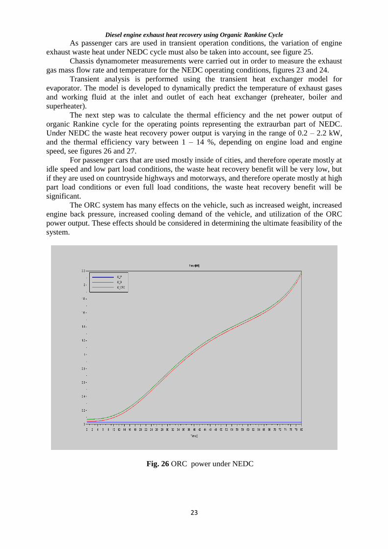
As passenger cars are used in transient operation conditions, the variation of engine
exhaust waste heat under NEDC cycle must also be taken into account, see figure 25.
Chassis dynamometer measurements were carried out in order to measure the exhaust
gas mass flow rate and temperature for the NEDC operating conditions, figures 23 and 24.
Transient analysis is performed using the transient heat exchanger model for
evaporator. The model is developed to dynamically predict the temperature of exhaust gases
and working fluid at the inlet and outlet of each heat exchanger (preheater, boiler and
superheater).
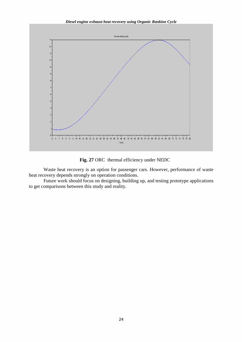
The next step was to calculate the thermal efficiency and the net power output of
organic Rankine cycle for the operating points representing the extraurban part of NEDC.
Under NEDC the waste heat recovery power output is varying in the range of 0.2 – 2.2 kW,
and the thermal efficiency vary between 1 – 14 %, depending on engine load and engine
speed, see figures 26 and 27.
For passenger cars that are used mostly inside of cities, and therefore operate mostly at
idle speed and low part load conditions, the waste heat recovery benefit will be very low, but
if they are used on countryside highways and motorways, and therefore operate mostly at high
part load conditions or even full load conditions, the waste heat recovery benefit will be
significant.
The ORC system has many effects on the vehicle, such as increased weight, increased
engine back pressure, increased cooling demand of the vehicle, and utilization of the ORC
power output. These effects should be considered in determining the ultimate feasibility of the
system.
Fig. 26 ORC power under NEDC
Diesel engine exhaust heat recovery using Organic Rankine Cycle
24
Fig. 27 ORC thermal efficiency under NEDC
Waste heat recovery is an option for passenger cars. However, performance of waste
heat recovery depends strongly on operation conditions.
Future work should focus on designing, building up, and testing prototype applications
to get comparisons between this study and reality.