
System VerilogOVM
27
D&R Industry Articles | Most Popular | SoC News Alerts | System Verilog + OVM: Mitigating Verification Challenges & Maximizing Reusability By Parag Goel, Pushkar Naik (Applied Micro) Abstract Verification – has been becoming a nightmare for engineers with the increasing requirements and complexity of the design. Mitigating the complexity of a verification environment with the increasing complexity of design verification can be re-defined as a CHALLENGE. System Verilog along with its library of classes –OVM, provides a platform to face this CHALLENGE. This paper explains how, in our endeavor to accomplish an ideal verification platform for our designs using System Verilog and a standard methodolog y(OVM) plus some in-house ideas over it, helped us to make a more practical and easy to use verification environme nt. The challenges spanned right from configuring the components, injecting the transactions to create various test scenarios, phasing of the test cases till the end of report generation etc. This paper also explains how SV & OVM has simplified a whole lot in controlling the messaging policy, sequences & sequencers layering, OOPs data patterning to fit certain environment architectur e requirements, barrier mechanism to overcome OVM phasing limitations and ready-made harness system for the sub-system integration, making things simpler & organized. It also explains how the addition of a thin layer between the OVM Methodology classes and our project's base classes helped us in shielding our projects from any changes in upcoming OVM releases as well as served to provide a place holder for any additional functionality in our base classes, without even touching the OVM source code as such. Towards the end, some points to ponder have been summarized based on our experience with OVM and some enhancements in Questasim / OVM are suggested. 1- Introduction Seventy percent of project time is consumed in verification and still there are Bug(s) in the design that are revealed after tape-o ut or at the customer end, that raises question(s) on the ability & the sincerity of the verification engineer and overall credibility of the organization as such. But the real question that needs to be raised is – Do we have enough technology available to create all possible stimuli to the DUT and gauge the amount of verification performed so far, quantitative ly, in order to confidently say that the DUT has been satisfactorily verified? Is the verification environment available to the tester, providing him/her, enough flexibility to exercise System V erilog + OVM: Mitigating V erification Challenges & Maximizing Reusability http://www.design-reuse.com/articles/?id=22264&print=yes 1 of 27 11/11/10 5:40 PM
-
Upload
prakash-jayaraman -
Category
Documents
-
view
231 -
download
0
Transcript of System VerilogOVM
8/8/2019 System VerilogOVM
http://slidepdf.com/reader/full/system-verilogovm 1/27
D&R Industry Articles | Most Popular | SoC News Alerts |
System Verilog + OVM: Mitigating Verification Challenges & Maximizing
Reusability
By Parag Goel, Pushkar Naik (Applied Micro)
Abstract
Verification – has been becoming a nightmare for engineers with the increasing requirements and complexity of the design. Mitigating the complexity of a verification
environment with the increasing complexity of design verification can be re-defined as a CHALLENGE. System Verilog along with its library of classes –OVM, provides
a platform to face this CHALLENGE.
This paper explains how, in our endeavor to accomplish an ideal verification platform for our designs using System Verilog and a standard methodology(OVM) plus
some in-house ideas over it, helped us to make a more practical and easy to use verification environment. The challenges spanned right from configuring the
components, injecting the transactions to create various test scenarios, phasing of the test cases till the end of report generation etc. This paper also explains how SV
& OVM has simplified a whole lot in controlling the messaging policy, sequences & sequencers layering, OOPs data patterning to fit certain environment architecture
requirements, barrier mechanism to overcome OVM phasing limitations and ready-made harness system for the sub-system integration, making things simpler &
organized.
It also explains how the addition of a thin layer between the OVM Methodology classes and our project's base classes helped us in shielding our projects from any
changes in upcoming OVM releases as well as served to provide a place holder for any additional functionality in our base classes, without even touching the OVM
source code as such. Towards the end, some points to ponder have been summarized based on our experience with OVM and some enhancements in Questasim /
OVM are suggested.
1- Introduction
Seventy percent of project time is consumed in verification and still there are Bug(s) in the design that are revealed after tape-out or at the customer end, that raises
question(s) on the ability & the sincerity of the verification engineer and overall credibility of the organization as such. But the real question that needs to be raised is
– Do we have enough technology available to create all possible stimuli to the DUT and gauge the amount of verification performed so far, quantitatively, in order to
confidently say that the DUT has been satisfactorily verified? Is the verification environment available to the tester, providing him/her, enough flexibility to exercise
System Verilog + OVM: Mitigating Verification Challenges & Maximizing Reusability http://www.design-reuse.com/articles/?id=22264&print=yes
1 of 27 11/11/10 5:40 PM
8/8/2019 System VerilogOVM
http://slidepdf.com/reader/full/system-verilogovm 2/27
the required test scenarios without modifying the golden test bench?
The Methodology we developed at AMCC tried to answer several such above questions utilizing the OVM/SV combination and some in-house ideas as mentioned
before.
This paper is broadly divided into the following sub-sections:
System Verilog concepts making environment simpler
Usage of Design patterns1. Usage of parameterized interface(s) in package(s)2.
Concept of harness for sub-system port mapping3.
1.
Advanced OVM Usage
Sequence / Sequencer layering1.
Single Class / Multiple Analysis Ports Usage2.
SV to C world host communication3.
2.
Work done to overcome OVM limitations
Messaging control in OVC's1.
OVM barrier enhanced phasing mechanism2.
3.
Miscellaneous topics
Sequence initiation methods comparison in OVM1.
Some points to ponder2.
Questasim / OVM Enhancements – moving forward3.
4.
2- OOP's Design Patterns (Singleton – Instantiating One Object)
As per the definition from the book Design Patterns: Elements of Reusable Object-Oriented Software – the Singleton design pattern must: "Ensure a class only has
one instance, and provide a global point of access to it." Usage of this pattern lets you take away control over the object instantiation process from the new operator.
This kind of pattern can be used over and above the classes available in the OVM library in cases where one might need to refer one and the same instance of the
class across the components and across the hierarchy. To achieve this objective one can use the concept of the Singleton pattern available in OOP's.
The two very common applications that can be thought for a VC based on System Verilog are as described below.
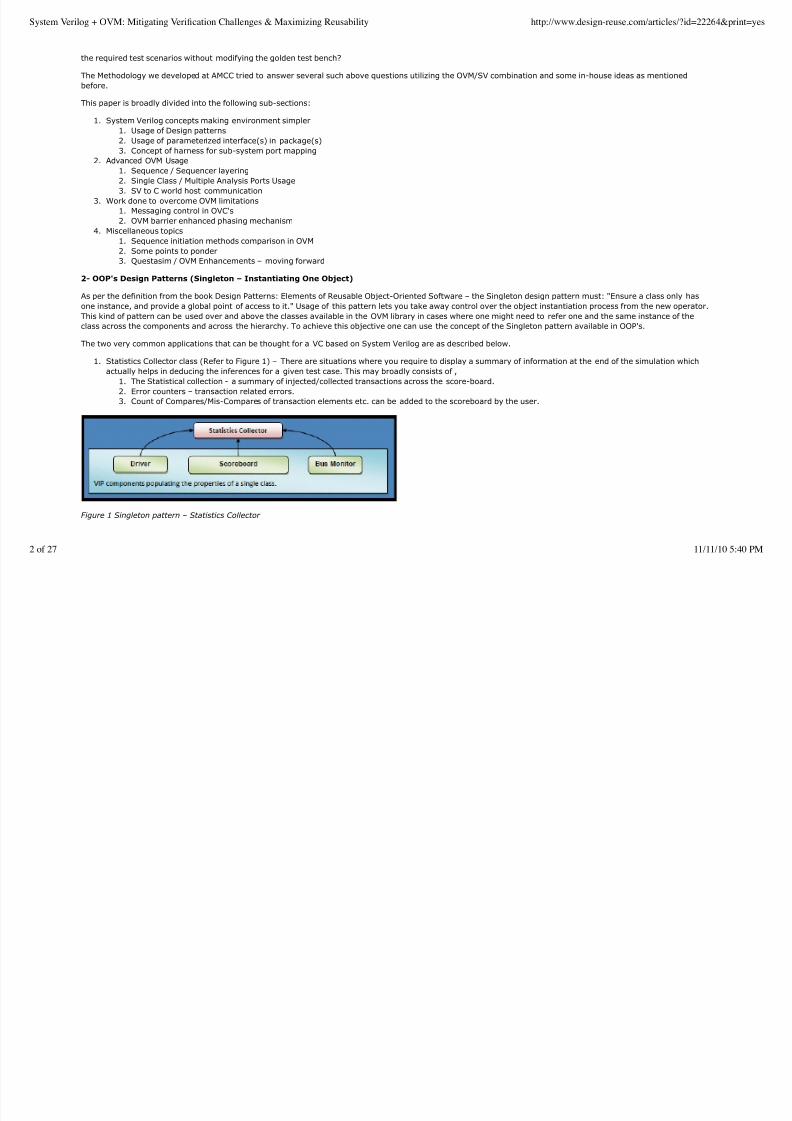
Statistics Collector class (Refer to Figure 1) – There are situations where you require to display a summary of information at the end of the simulation which
actually helps in deducing the inferences for a given test case. This may broadly consists of ,
The Statistical collection - a summary of injected/collected transactions across the score-board.1.
Error counters – transaction related errors.2.
Count of Compares/Mis-Compares of transaction elements etc. can be added to the scoreboard by the user.3.
1.
Figure 1 Singleton pattern – Statistics Collector
System Verilog + OVM: Mitigating Verification Challenges & Maximizing Reusability http://www.design-reuse.com/articles/?id=22264&print=yes
2 of 27 11/11/10 5:40 PM
8/8/2019 System VerilogOVM
http://slidepdf.com/reader/full/system-verilogovm 3/27
This block will necessarily be a singleton class that will contain all the properties related to the above mentioned points. These properties shall be populated &
updated from several components sitting in the VIP environment, and at the end of simulation it will display the complete information collected in a simple & easy to
understand manner. Needless to mention, how OVM also aids in such scenario, by providing certain in-built methods for printing messages uniformly in the report
phase etc.
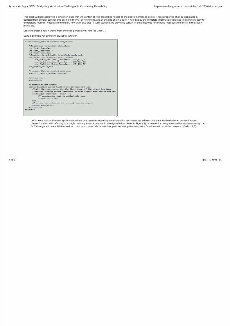
Let's understand how it works from the code perspective [Refer to Code 1]:
Code 1 Example for Singleton Statistics collector
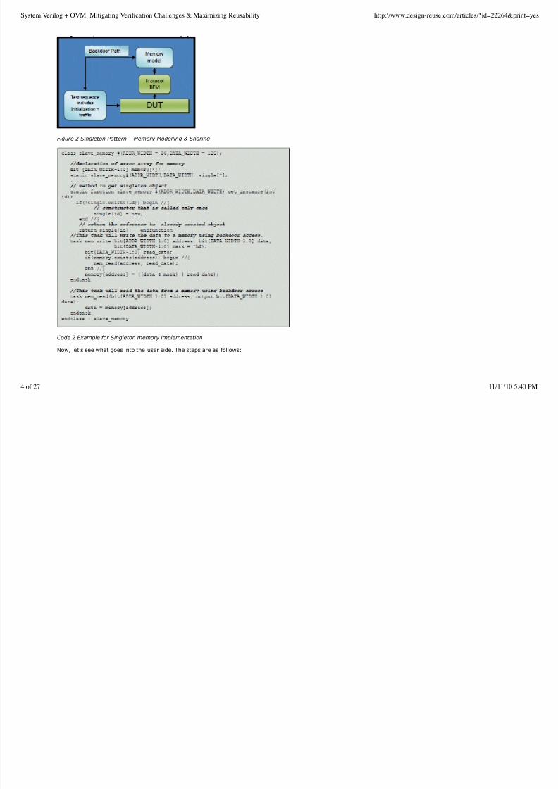
Let's take a look at the next application, where one requires modeling a memory with parameterized address and data width which can be used across
classes/models, still referring to a single memory array. As shown in the figure below (Refer to Figure 2), a memory is being accessed for reads/writes by the
DUT through a Protocol BFM as well as it can be accessed via. a backdoor path accessing the read/write functions written in the memory. [Code : 2,3]
1.
System Verilog + OVM: Mitigating Verification Challenges & Maximizing Reusability http://www.design-reuse.com/articles/?id=22264&print=yes
3 of 27 11/11/10 5:40 PM
8/8/2019 System VerilogOVM
http://slidepdf.com/reader/full/system-verilogovm 4/27
Figure 2 Singleton Pattern – Memory Modelling & Sharing
Code 2 Example for Singleton memory implementation
Now, let's see what goes into the user side. The steps are as follows:
System Verilog + OVM: Mitigating Verification Challenges & Maximizing Reusability http://www.design-reuse.com/articles/?id=22264&print=yes
4 of 27 11/11/10 5:40 PM
8/8/2019 System VerilogOVM
http://slidepdf.com/reader/full/system-verilogovm 5/27
Code 3 Example for Singleton memory usage
To summarize, using this pattern, one can refer to the same instance anywhere within one's environment. The examples discussed were, when one wants to collect
the statistics from all the VIP components and display the same as the final report at the end of simulation, and when a single instance of memory is used across
environment that is accessed for read/writes by several VIP components.
Singleton applies to ‘has_a' kind of relationship. Now let's see when the class being treated as Singleton has child classes leading to ‘is_a' kind of relationship as well.
To achieve the same we can make the constructor protected, so that various subclasses get to inherit the same constructor. But as a general thumb rule, Singleton
and subclassing should not be mixed to keep things simpler.
Disadvantages:
It creates an object in a given namespace, and the whole idea of namespace defies the OOP's objective to remove the clutter of namespaces1.
Having only one such global object at a particular time doesn't mean another one can't be created inadvertently in another namespace, giving you some very
hard to debug issues.
2.
3- Use of Parameterized Interface(s) in a Package
Classes are dynamic in nature while interfaces are static in nature and hence cannot be directly instantiated in a class. So, typically, a real interface instance is
created in the top module (or program block) and virtual interface instances are created in various classes where there is a need to access the interface. But we need
to connect the various virtual interfaces to the equivalent real interface somewhere.
One of the ‘not so elegant ways' is to hierarchically pass a virtual interface instance down the layers.
OVM suggests a cleaner solution to this, for OVC development.
Define a virtual interface package and instantiate a virtual interface for each of the real interface(s) instantiated in the top module or program block[Refer to Figure
5]. Then in the top module or program block, import the virtual interface package and connect the package's virtual interface(s) to the corresponding real interface(s)
there. In the various classes where interface access is required, define local instances of the required virtual interface(s). Then import the virtual interface package in
each of these classes and connect the local virtual interface instance(s) to the corresponding ones in the imported package.
System Verilog + OVM: Mitigating Verification Challenges & Maximizing Reusability http://www.design-reuse.com/articles/?id=22264&print=yes
5 of 27 11/11/10 5:40 PM
8/8/2019 System VerilogOVM
http://slidepdf.com/reader/full/system-verilogovm 6/27
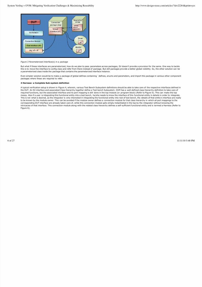
Figure 3 Parameterized Interface(s) in a package
But what if these interfaces are parameterized, how do we plan to pass parameters across packages, SV doesn't provide a provision for the same. One way to tackle
this is to move the interface to config class and refer from there instead of package. But still packages provide a better global visibility. So, the other solution can bea parameterized class inside the package that contains the parameterized interface instance.
Even simpler solution would be to make a package of global defines containing ̀ defines, enums and parameters, and import this package in various other component
packages where these are required to refer.
4 Harness- a Complete Sub-system definition
A typical verification setup is shown in Figure 4, wherein, various Test Bench Subsystem definitions should be able to take care of the respective interfaces defined in
the DUT. An SV interface and associated Class hierarchy together define a Test bench Subsystem. OVM has a well-defined class hierarchy definition to take care of
required functions, but the associated interface and its port mapping is still done in the top module (or program block) (Refer to Figure 5). This can make the top
messy. Also if a user is integrating this functional entity into a test bench, he/she needs to know the interface of this functional entity in details in order to integrate.
This is not what is desired, as the integrator is only interested in integrating the functional entity into rest of test bench, the details of that entity's interface are really
to be known by the module owner. This can be avoided if the module owner defines a connection module for that class hierarchy in which all port mappings to the
corresponding DUT interface are already taken care of, while this connection module gets simply instantiated in the top by the integrator without knowing theintricacies of that interface. This connection module along-with the related class hierarchy defines a self-sufficient functional entity and is termed a Harness (Refer to
Figure 6).
System Verilog + OVM: Mitigating Verification Challenges & Maximizing Reusability http://www.design-reuse.com/articles/?id=22264&print=yes
6 of 27 11/11/10 5:40 PM
8/8/2019 System VerilogOVM
http://slidepdf.com/reader/full/system-verilogovm 7/27
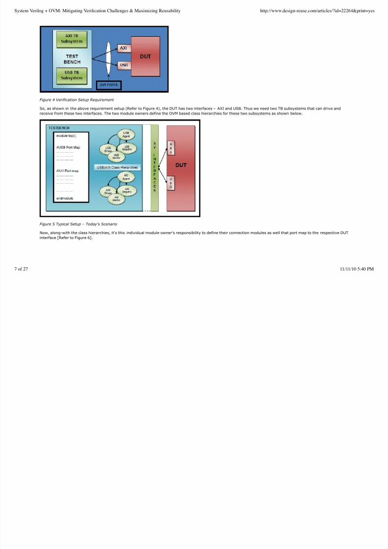
Figure 4 Verification Setup Requirement
So, as shown in the above requirement setup (Refer to Figure 4), the DUT has two interfaces – AXI and USB. Thus we need two TB subsystems that can drive and
receive from these two interfaces. The two module owners define the OVM based class hierarchies for these two subsystems as shown below.
Figure 5 Typical Setup – Today's Scenario
Now, along-with the class hierarchies, it's this individual module owner's responsibility to define their connection modules as well that port map to the respective DUT
interface [Refer to Figure 6].
System Verilog + OVM: Mitigating Verification Challenges & Maximizing Reusability http://www.design-reuse.com/articles/?id=22264&print=yes
7 of 27 11/11/10 5:40 PM
8/8/2019 System VerilogOVM
http://slidepdf.com/reader/full/system-verilogovm 8/27
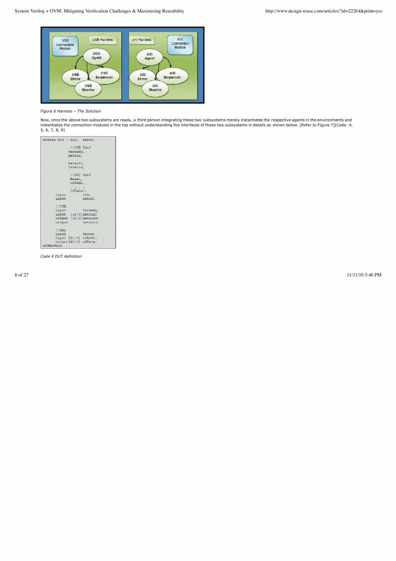
Figure 6 Harness – The Solution
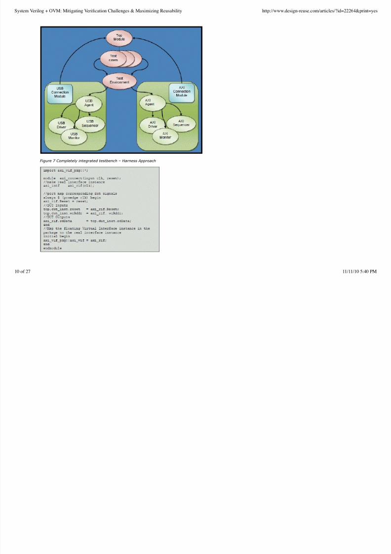
Now, once the above two subsystems are ready, a third person integrating these two subsystems merely instantiates the respective agents in the environments and
instantiates the connection modules in the top without understanding the interfaces of these two subsystems in details as shown below. [Refer to Figure 7][Code: 4,
5, 6, 7, 8, 9]
Code 4 DUT definition
System Verilog + OVM: Mitigating Verification Challenges & Maximizing Reusability http://www.design-reuse.com/articles/?id=22264&print=yes
8 of 27 11/11/10 5:40 PM
8/8/2019 System VerilogOVM
http://slidepdf.com/reader/full/system-verilogovm 9/27
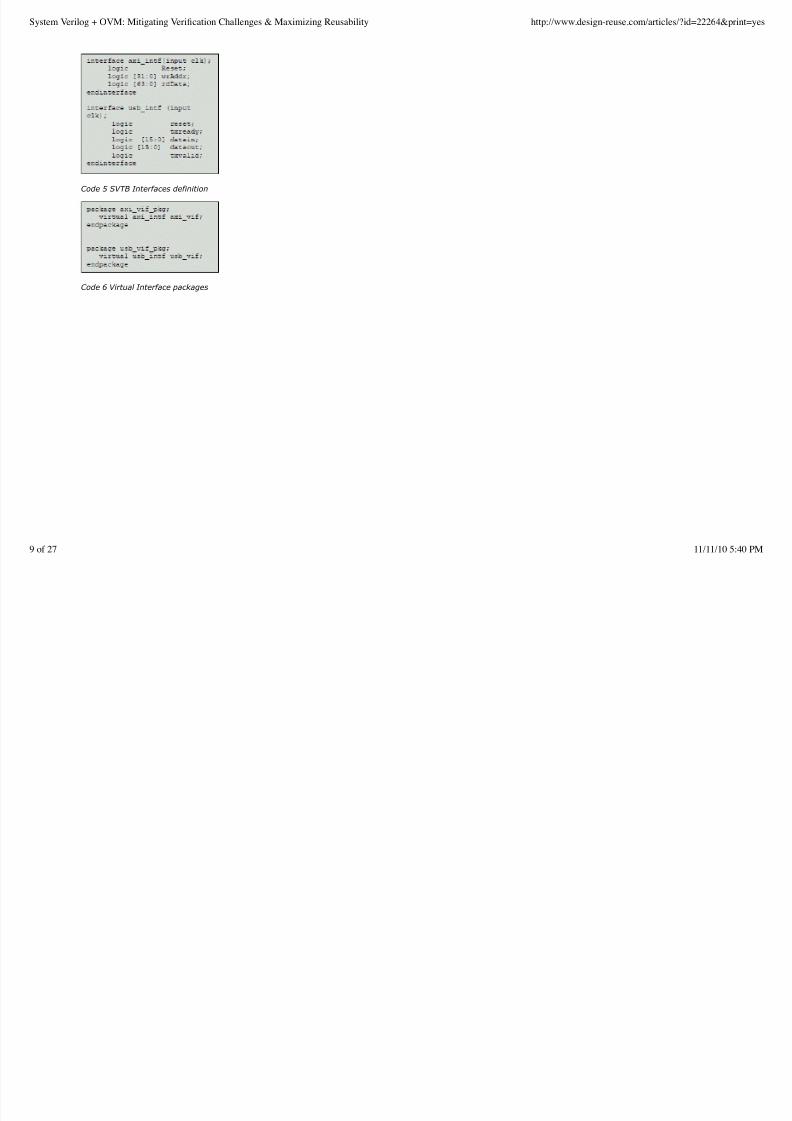
Code 5 SVTB Interfaces definition
Code 6 Virtual Interface packages
System Verilog + OVM: Mitigating Verification Challenges & Maximizing Reusability http://www.design-reuse.com/articles/?id=22264&print=yes
9 of 27 11/11/10 5:40 PM
8/8/2019 System VerilogOVM
http://slidepdf.com/reader/full/system-verilogovm 10/27
Figure 7 Completely integrated testbench – Harness Approach
System Verilog + OVM: Mitigating Verification Challenges & Maximizing Reusability http://www.design-reuse.com/articles/?id=22264&print=yes
10 of 27 11/11/10 5:40 PM
8/8/2019 System VerilogOVM
http://slidepdf.com/reader/full/system-verilogovm 11/27
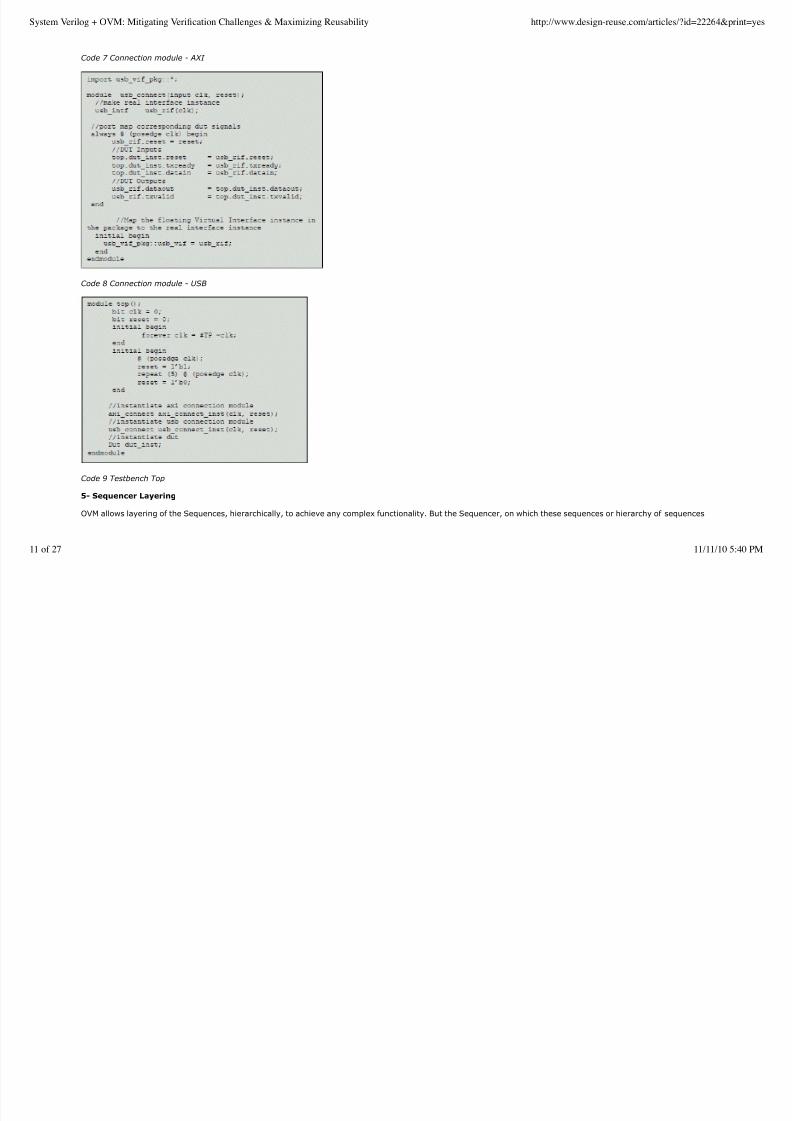
Code 7 Connection module - AXI
Code 8 Connection module - USB
Code 9 Testbench Top
5- Sequencer Layering
OVM allows layering of the Sequences, hierarchically, to achieve any complex functionality. But the Sequencer, on which these sequences or hierarchy of sequences
System Verilog + OVM: Mitigating Verification Challenges & Maximizing Reusability http://www.design-reuse.com/articles/?id=22264&print=yes
11 of 27 11/11/10 5:40 PM
8/8/2019 System VerilogOVM
http://slidepdf.com/reader/full/system-verilogovm 12/27
is started, expects a given type of ovm_sequence_item derivative, as specified in the Sequencer definition.
There can be a requirement in a Verification Environment that few Sequences work on one type of ovm_sequence_item derivative and the output of these Sequences
is required to be fed to another type of ovm_sequence_item derivative. Thus a translation is required in between, to convert one type of ovm_sequence_item
derivative to another, before the Sequencer and Driver configured to accept second ovm_sequence_item derivative, can consume it.
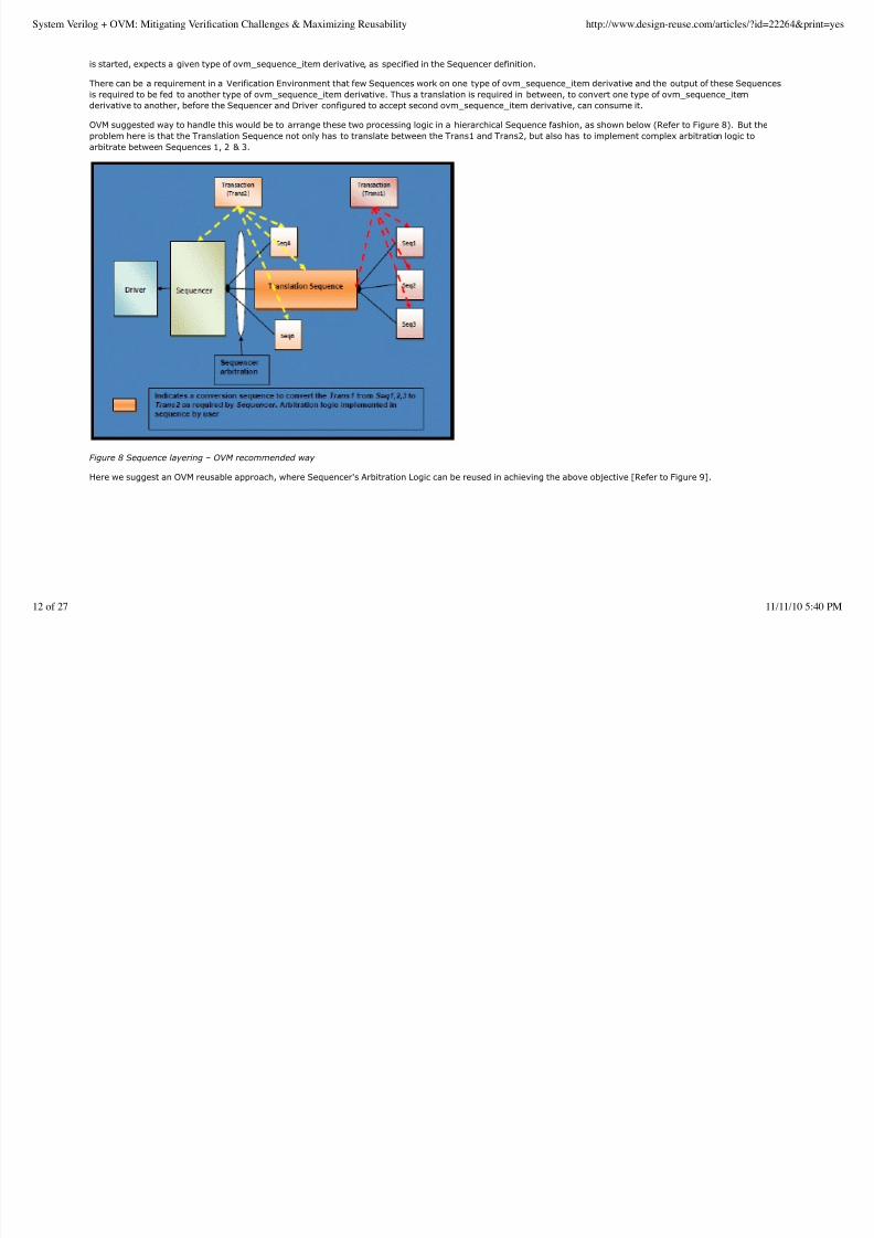
OVM suggested way to handle this would be to arrange these two processing logic in a hierarchical Sequence fashion, as shown below (Refer to Figure 8). But the
problem here is that the Translation Sequence not only has to translate between the Trans1 and Trans2, but also has to implement complex arbitration logic to
arbitrate between Sequences 1, 2 & 3.
Figure 8 Sequence layering – OVM recommended way
Here we suggest an OVM reusable approach, where Sequencer's Arbitration Logic can be reused in achieving the above objective [Refer to Figure 9].
System Verilog + OVM: Mitigating Verification Challenges & Maximizing Reusability http://www.design-reuse.com/articles/?id=22264&print=yes
12 of 27 11/11/10 5:40 PM
8/8/2019 System VerilogOVM
http://slidepdf.com/reader/full/system-verilogovm 13/27
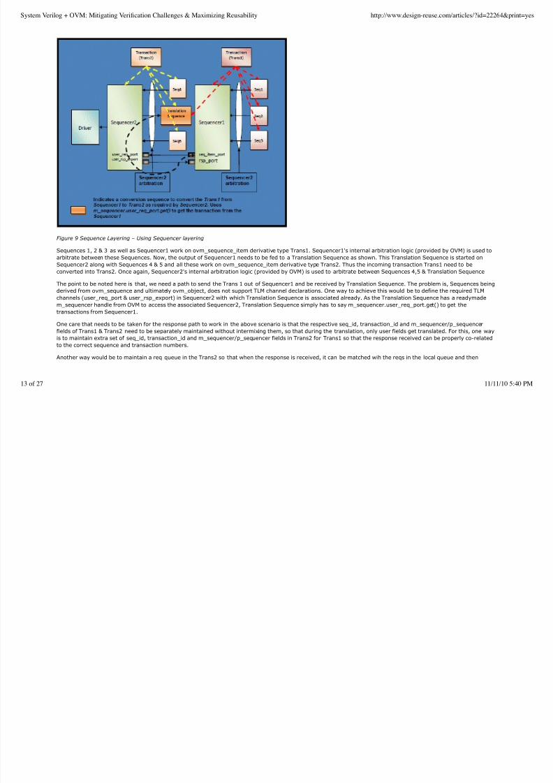
Figure 9 Sequence Layering – Using Sequencer layering
Sequences 1, 2 & 3 as well as Sequencer1 work on ovm_sequence_item derivative type Trans1. Sequencer1's internal arbitration logic (provided by OVM) is used to
arbitrate between these Sequences. Now, the output of Sequencer1 needs to be fed to a Translation Sequence as shown. This Translation Sequence is started on
Sequencer2 along with Sequences 4 & 5 and all these work on ovm_sequence_item derivative type Trans2. Thus the incoming transaction Trans1 need to be
converted into Trans2. Once again, Sequencer2's internal arbitration logic (provided by OVM) is used to arbitrate between Sequences 4,5 & Translation Sequence
The point to be noted here is that, we need a path to send the Trans 1 out of Sequencer1 and be received by Translation Sequence. The problem is, Sequences beingderived from ovm_sequence and ultimately ovm_object, does not support TLM channel declarations. One way to achieve this would be to define the required TLM
channels (user_req_port & user_rsp_export) in Sequencer2 with which Translation Sequence is associated already. As the Translation Sequence has a readymade
m_sequencer handle from OVM to access the associated Sequencer2, Translation Sequence simply has to say m_sequencer.user_req_port.get() to get the
transactions from Sequencer1.
One care that needs to be taken for the response path to work in the above scenario is that the respective seq_id, transaction_id and m_sequencer/p_sequencer
fields of Trans1 & Trans2 need to be separately maintained without intermixing them, so that during the translation, only user fields get translated. For this, one way
is to maintain extra set of seq_id, transaction_id and m_sequencer/p_sequencer fields in Trans2 for Trans1 so that the response received can be properly co-related
to the correct sequence and transaction numbers.
Another way would be to maintain a req queue in the Trans2 so that when the response is received, it can be matched wih the reqs in the local queue and then
System Verilog + OVM: Mitigating Verification Challenges & Maximizing Reusability http://www.design-reuse.com/articles/?id=22264&print=yes
13 of 27 11/11/10 5:40 PM
8/8/2019 System VerilogOVM
http://slidepdf.com/reader/full/system-verilogovm 14/27
co-related to the correct sequence and transaction numbers.
6- Single Class / Multiple Analysis ports
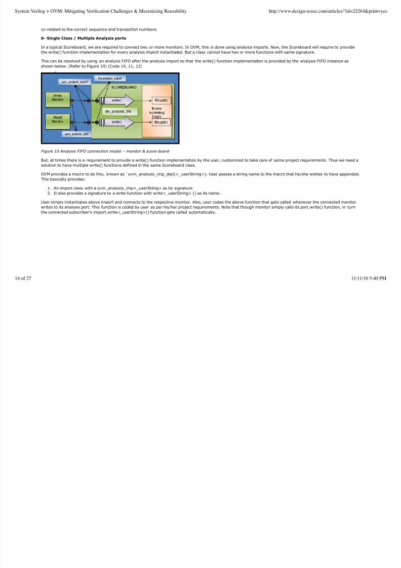
In a typical Scoreboard, we are required to connect two or more monitors. In OVM, this is done using analysis imports. Now, the Scoreboard will require to provide
the write() function implementation for every analysis import instantiated. But a class cannot have two or more functions with same signature.
This can be resolved by using an analysis FIFO after the analysis import so that the write() function implementation is provided by the analysis FIFO instance as
shown below. (Refer to Figure 10) (Code 10, 11, 12)
Figure 10 Analysis FIFO connection model – monitor & score-board
But, at times there is a requirement to provide a write() function implementation by the user, customized to take care of some project requirements. Thus we need a
solution to have multiple write() functions defined in the same Scoreboard class.
OVM provides a macro to do this, known as ̀ ovm_analysis_imp_decl(<_userString>). User passes a string name to the macro that he/she wishes to have appended.
This basically provides:
An import class with a ovm_analysis_imp<_userString> as its signature1.
It also provides a signature to a write function with write<_userString> () as its name.2.
User simply instantiates above import and connects to the respective monitor. Also, user codes the above function that gets called whenever the connected monitor
writes to its analysis port. This function is coded by user as per his/her project requirements. Note that though monitor simply calls its port.write() function, in turnthe connected subscriber's import.write<_userString>() function gets called automatically.
System Verilog + OVM: Mitigating Verification Challenges & Maximizing Reusability http://www.design-reuse.com/articles/?id=22264&print=yes
14 of 27 11/11/10 5:40 PM
8/8/2019 System VerilogOVM
http://slidepdf.com/reader/full/system-verilogovm 15/27
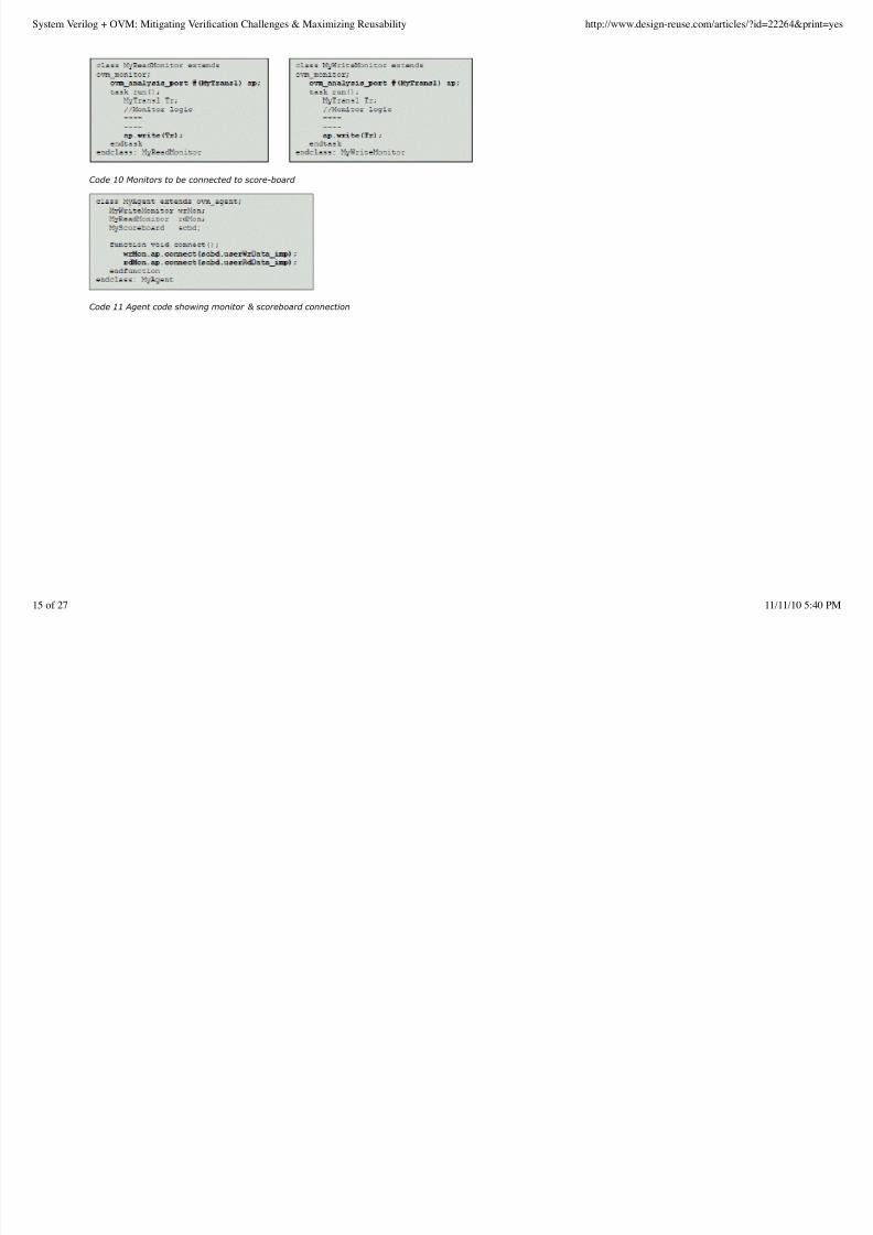
Code 10 Monitors to be connected to score-board
Code 11 Agent code showing monitor & scoreboard connection
System Verilog + OVM: Mitigating Verification Challenges & Maximizing Reusability http://www.design-reuse.com/articles/?id=22264&print=yes
15 of 27 11/11/10 5:40 PM

8/8/2019 System VerilogOVM
http://slidepdf.com/reader/full/system-verilogovm 16/27
Code 12 Score-board showing implementation
System Verilog + OVM: Mitigating Verification Challenges & Maximizing Reusability http://www.design-reuse.com/articles/?id=22264&print=yes
16 of 27 11/11/10 5:40 PM
8/8/2019 System VerilogOVM
http://slidepdf.com/reader/full/system-verilogovm 17/27
7- SV world to C world - Host Communication
In case of SOC projects, often there is a need to communicate across from SV World to ‘C' World and back, to accomplish a particular test scenario.
Now, in case of Module Level Verification Environments, where embedded host processor is typically absent, SV to C communication and back can simply be SV DPI
Calls. But when embedded host processor is in place at Chip Level Verification Environment, shared memory is one way to achieve the communication between the
SV and ‘C' Worlds.
Typically, we randomize the control parameters in the SV World as per the constraints specified in the test-case/sequence/transfer class, but the programming of
DUT registers for DUT initialization has to be performed by the embedded processor only, as per the real world SOC requirement.
The idea here is to reuse the ‘C' code written at Module Level Verification into the Chip Level Verification.
Thus there is a need to send across the randomized set of data from SV World to the ‘C' World. Once the ‘C' program executes on the embedded processor (or
through DPI call at Module Level) and utilizes the data that came from SV World, it now has some programming sequence data ready to program the DUT registers.
But to actually perform this programming, this data has to be brought back from the ‘C' World to the SV World where some SV module can drive the DUT Register
Programming interface using the data received from the ‘C' World.
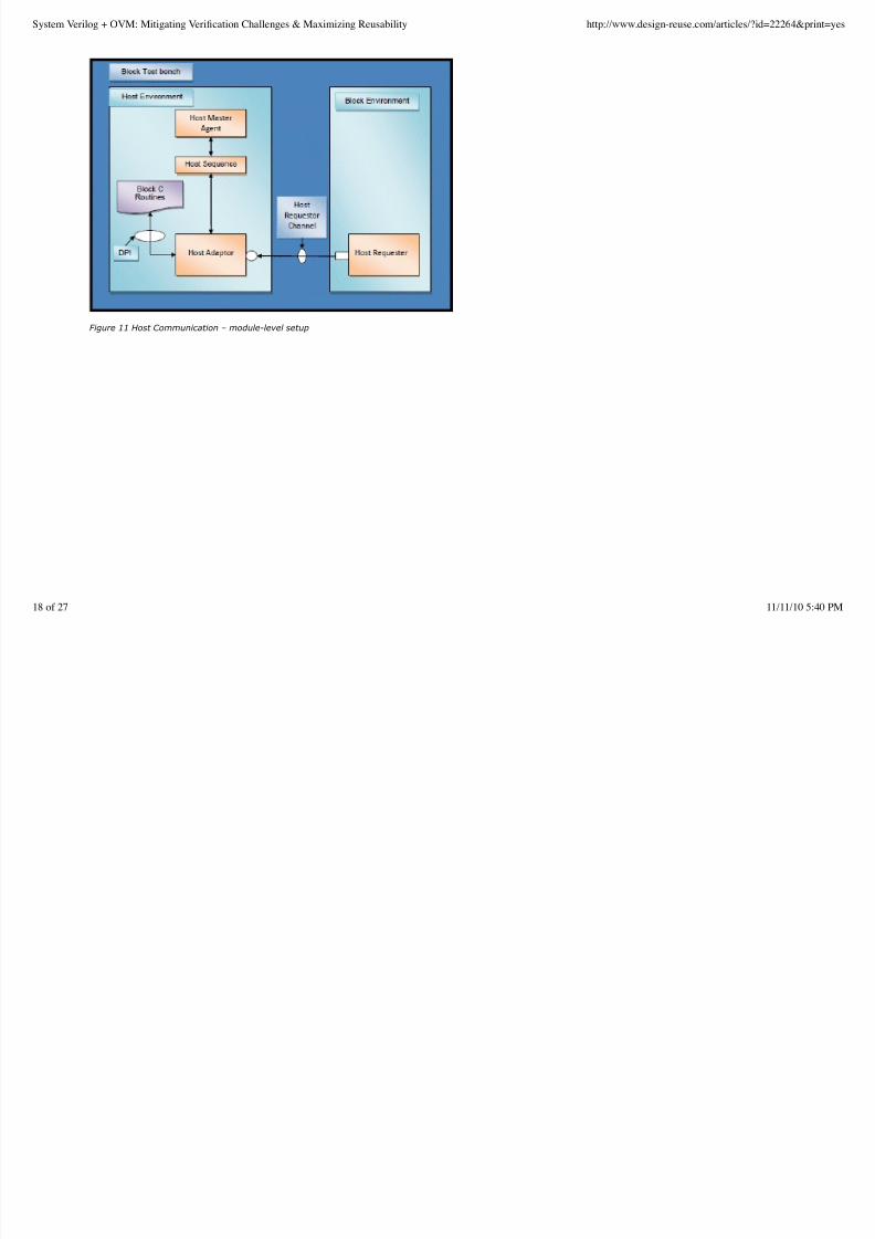
To accomplish the above communication, reusable verification blocks can be defined to be used across various project modules. One of the proposed definitions of
these blocks is that we define a Host Adapter block and a Host Requester block. [Refer to figure 11] There will be a Singleton instance of Host Adapter in a project at
any given time. Every SV Module that wishes to send data to the ‘C' World first extends the host requester block for customizing the data to be sent across as per
that modules requirement and then connects to the singleton Host Adapter instance using a host requester channel (TLM Channel).
A generic data structure can be defined that is interpreted by any Host Requester and Host Adapter.
This data structure can contain following fields: block_id, task_id, data[], control[]. The contents of data [] and control[] can be customized by the individual modules
as per their requirement.
Every Module Level Verification Environment provides a ‘C' file containing the tasks required to execute to achieve that Module's DUT Register Programming. Also, in
that file, it provides a host task table consisting of entries of task string name and corresponding function pointer.
When a Host Requester sends a request in the form of a structure defined above, to the Host Adapter, it gets stored in the Adapter's in-built Queue (FIFO). The
various barriers defined in Adapter like the init_barrier, run_barrier, check_barrier etc pops out the request from Queue one-by-one at the appropriate barrier timing
and calls the Host Adapter Generic ‘C' function process requests() for handling the requests.
In case of Module Level Verification Environment, as discussed before, this will be purely a DPI-C call.
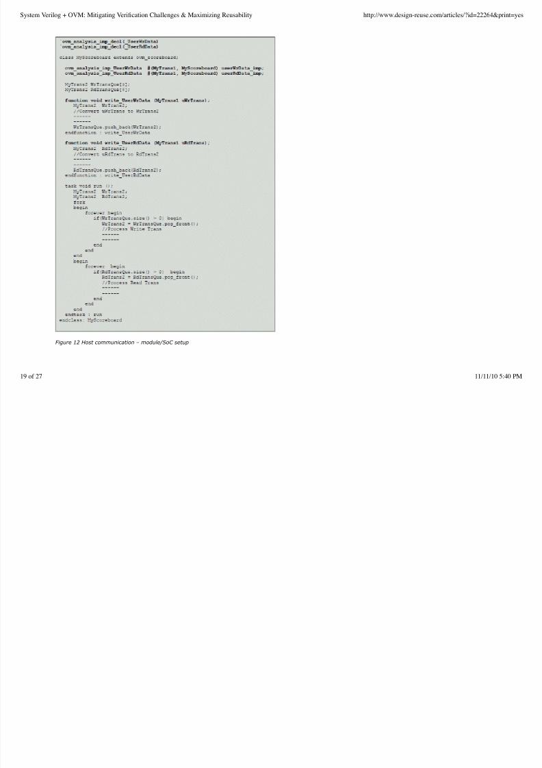
In case of Chip Level Verification Environment, this will be through a shared memory so that the Adapter Generic C function(s) running on embedded host processor
can pick up the request through shared memory and execute it.[ Refer to figure 12]
This Generic ‘C' function looks at the block_id from the request and figures out which host task table to look into. Then it uses the task_id in the form of a string from
the request to lookup for this function in this table. Once it finds it, it simply calls the mapping function pointer in the found entry with the data [] and control[] as
arguments else flags a fatal error. This User ‘C' function called by the Generic ‘C' function may result in a call, back to SV World.
Again in case of Module Level Verification Environment, this will simply be a DPI SV call to the SV Adapter exported function(s). In case of Chip Level Verification
Environment, this will be through a shared memory so that some Adapter SV process waiting for the ‘C' side to setup data in shared memory gets kicked off seeing
the data there and then executes the associated tasks in the DUT Register Programming module in the SV domain to get the appropriate DUT Registers programmed.
In a similar fashion, interrupts handling can be taken care of in the Module Level Verification Environments where actual host processor is missing, so the ISR routine
gets called through the DPI C calls. At Chip Level, there will be actual processor to handle the interrupts anyways.
System Verilog + OVM: Mitigating Verification Challenges & Maximizing Reusability http://www.design-reuse.com/articles/?id=22264&print=yes
17 of 27 11/11/10 5:40 PM
8/8/2019 System VerilogOVM
http://slidepdf.com/reader/full/system-verilogovm 18/27
Figure 11 Host Communication – module-level setup
System Verilog + OVM: Mitigating Verification Challenges & Maximizing Reusability http://www.design-reuse.com/articles/?id=22264&print=yes
18 of 27 11/11/10 5:40 PM
8/8/2019 System VerilogOVM
http://slidepdf.com/reader/full/system-verilogovm 19/27
Figure 12 Host communication – module/SoC setup
System Verilog + OVM: Mitigating Verification Challenges & Maximizing Reusability http://www.design-reuse.com/articles/?id=22264&print=yes
19 of 27 11/11/10 5:40 PM
8/8/2019 System VerilogOVM
http://slidepdf.com/reader/full/system-verilogovm 20/27
8- Messaging Control in OVC's
OVM provides a comprehensive and robust messaging interface, but while deploying messaging interface in an OVC we found certain limitations with its usage.
Problem Statement: A user wants to associate an ID with each and every component of the VIP to distinguish where the particular message pop's from in the
transcript. By default he/she wants to associate a designated severity for a given Message ID say for example, OVM_WARNING, but in a certain test scenario the test
writer feels that it needs to be upgraded to the OVM_ERROR/OVM_FATAL with the message still in the transcript. OVM as such doesn't provide any method to achieve
a dynamic change in message severity, runtime.
Another example would be, say there is an error condition that is intentionally injected in negative testing scenario, and the OVC that you have coded might give afatal message for the same and stop the simulation. But you don't want that to happen, and at the same time you require that the message appears in your
transcript that affirms that the scenario is created. So you downgrade the severity to warning, temporarily, and now you see this as a warning message instead of
fatal, without modifying the main code!
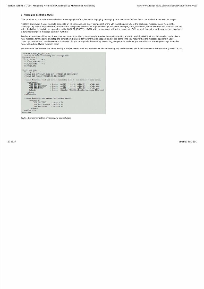
Solution: One can achieve the same writing a simple macro over and above OVM. Let's directly jump to the code to get a look and feel of the solution. [Code: 13, 14]
Code 13 Implementation of messaging control class
System Verilog + OVM: Mitigating Verification Challenges & Maximizing Reusability http://www.design-reuse.com/articles/?id=22264&print=yes
20 of 27 11/11/10 5:40 PM
8/8/2019 System VerilogOVM
http://slidepdf.com/reader/full/system-verilogovm 21/27
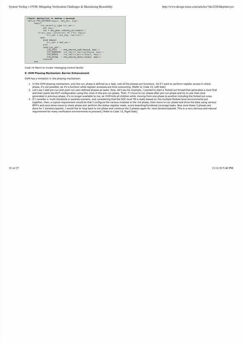
Code 14 Macro to invoke messaging control facility
9- OVM Phasing Mechanism: Barrier Enhancement
OVM has a limitation in the phasing mechanism:
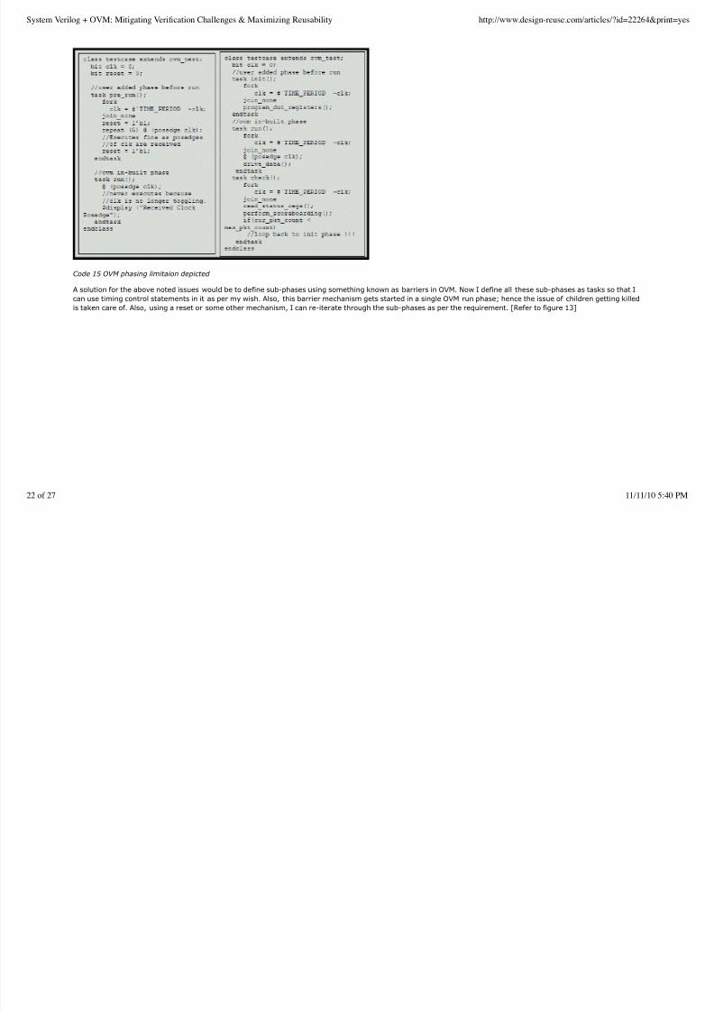
In the OVM phasing mechanism, only the run phase is defined as a task, rest all the phases are functions. So if I want to perform register access in checkphase, it's not possible, as it's a function while register accesses are time consuming. [Refer to Code 15, Left Side]
1.
Let's say I add pre-run and post-run user-defined phases as tasks. Now, let's say for example, I wanted to start a forked out thread that generates a clock first
and then starts the DUT configuration using this clock in the pre-run phase. Then i f I move to run phase after pre-run phase and try to use that clock
generated in previous phase, it's no longer available to me, as OVM kills all children while moving from one phase to another including the forked out ones.
2.
If I consider a multi-iterations or packets scenario, and considering that the SOC level TB is really based on the multiple Module level environments put
together, then, a typical requirement would be that I configure the various modules in the init phase, then move to run phase and drive the data using various
BFM's and once done move to check phase and perform the status register reads, score-boarding/functional coverage tasks. Now once these 3 phases are
done for 1 iteration/packet, I would like to loop back to init phase and continue the 3 phases again for next iteration/packet. This is a very obvious and natural
requirement for many verification environments to proceed.[ Refer to Code 15, Right Side]
3.
System Verilog + OVM: Mitigating Verification Challenges & Maximizing Reusability http://www.design-reuse.com/articles/?id=22264&print=yes
21 of 27 11/11/10 5:40 PM
8/8/2019 System VerilogOVM
http://slidepdf.com/reader/full/system-verilogovm 22/27
Code 15 OVM phasing limitaion depicted
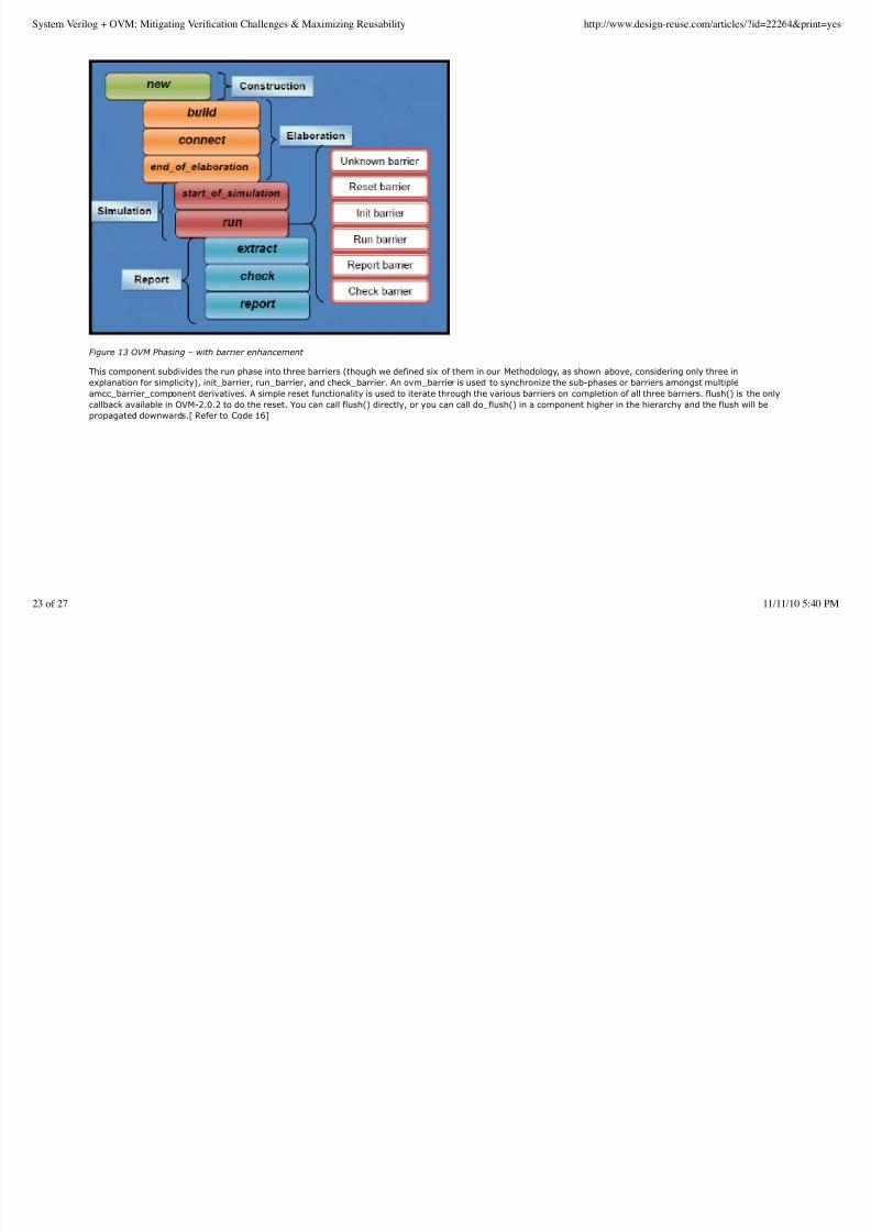
A solution for the above noted issues would be to define sub-phases using something known as barriers in OVM. Now I define all these sub-phases as tasks so that I
can use timing control statements in it as per my wish. Also, this barrier mechanism gets started in a single OVM run phase; hence the issue of children getting killed
is taken care of. Also, using a reset or some other mechanism, I can re-iterate through the sub-phases as per the requirement. [Refer to figure 13]
System Verilog + OVM: Mitigating Verification Challenges & Maximizing Reusability http://www.design-reuse.com/articles/?id=22264&print=yes
22 of 27 11/11/10 5:40 PM
8/8/2019 System VerilogOVM
http://slidepdf.com/reader/full/system-verilogovm 23/27
Figure 13 OVM Phasing – with barrier enhancement
This component subdivides the run phase into three barriers (though we defined six of them in our Methodology, as shown above, considering only three in
explanation for simplicity), init_barrier, run_barrier, and check_barrier. An ovm_barrier is used to synchronize the sub-phases or barriers amongst multiple
amcc_barrier_component derivatives. A simple reset functionality is used to iterate through the various barriers on completion of all three barriers. flush() is the only
callback available in OVM-2.0.2 to do the reset. You can call flush() directly, or you can call do_flush() in a component higher in the hierarchy and the flush will be
propagated downwards.[ Refer to Code 16]
System Verilog + OVM: Mitigating Verification Challenges & Maximizing Reusability http://www.design-reuse.com/articles/?id=22264&print=yes
23 of 27 11/11/10 5:40 PM

8/8/2019 System VerilogOVM
http://slidepdf.com/reader/full/system-verilogovm 24/27
Code 16 OVM Phasing enhanced using barriers
10- Sequence Initiation methods
Sequences can be initiated on the sequencer using the following 2 methods:
The start () method – In case of hierarchical sequences, typically, a Test-Case instantiates a Complex Sequence and a Complex Sequence in turn instantiates a
Basic Sequence, in the build() phase. In the run() phase, a Test-Case starts the Complex Sequence and the Complex Sequence starts the Basic Sequence by
1.
System Verilog + OVM: Mitigating Verification Challenges & Maximizing Reusability http://www.design-reuse.com/articles/?id=22264&print=yes
24 of 27 11/11/10 5:40 PM
8/8/2019 System VerilogOVM
http://slidepdf.com/reader/full/system-verilogovm 25/27
calling the respective Sequence object's start() method at the required time and passing the Sequencer handle to associate with it. When a Complex Sequence
is instantiated in a Test-Case, a complete Sequencer hierarchy has to be specified as argument to start() call for the sequencer association. But when a
Complex Sequence instantiates a Basic Sequence, the Complex Sequence already has an in-built handle called m_sequencer to point to the associated
Sequencer, that gets it correct value when the Complex Sequence is instantiated in the Test-Case above it and the associated Sequencer's hierarchical path is
passed to it.
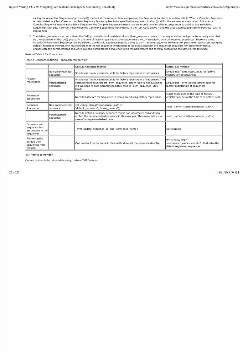
The default_sequence method – Here, the OVM provided in-built variable called default_sequence points to the sequence that will get automatically executed
by the sequencer in the run() phase. At the time of factory registration, the sequence is directly associated with the required sequencer. There are three
in-built OVM provided Sequences and by default, the default_sequence method points to ovm_random sequence. However, for parameterized classes using thedefault_sequence method, one must ensure that the top sequence which needs to be associated with the sequencer should be non-parameterized i.e.
encapsulate the parameterized sequence in a non parameterized sequence fixing the parameters and thereby associating the same in the test case.
2.
Refer to Table 1 for Comparison
Table 1 Sequence Initiation – approach comparision
Default_sequence method Start() call method
Factory
registration
Non-parameterized
sequenceShould use ̀ ovm_sequence_utils for factory registration of sequences.
Should use ̀ ovm_object_utils for factory
registration of sequences
Parameterized
sequence
Should use ̀ ovm_sequence_utils for factory registration of sequences. The
corresponding counterpart ̀ ovm_sequence_param_utils is not available;
still we need to pass parameters in this case in ̀ ovm_sequence_utilsitself.
Should use `ovm_object_param_utils for
factory registration of sequences
Sequencer
associationNeed to associate the Sequence to Sequencer during factory registration
Is not associated at the time of factory
registration, but at the time of seq.start() call
.
Sequence
Association
Non-parameterized
sequence
set_config_string("<sequencer_path>",
"default_sequence", "<seq_name>");<seq_name>.start(<sequencer_path>)
Parameterized
sequence
Need to define a wrapper sequence that is non-parameterized and then
embed the parameterized sequence in this wrapper. Then associate as in
case of non-parameterized case
<seq_name>.start(<sequencer_path>)
Sequence and
sequence itemassociation in the
sequencer
`ovm_update_sequence_lib_and_item(<seq_item>) Not required
Removing the
default OVM
sequences from
the pool
One need not do the same in this method we set the sequence directly.
We need to make
<sequencer_name>.count=0; to disable the
default registered sequences
11- Points to Ponder
Certain caution to be taken while using certain OVM features
System Verilog + OVM: Mitigating Verification Challenges & Maximizing Reusability http://www.design-reuse.com/articles/?id=22264&print=yes
25 of 27 11/11/10 5:40 PM
8/8/2019 System VerilogOVM
http://slidepdf.com/reader/full/system-verilogovm 26/27
Whenever you do a set_config_*(), it is a good practice to always do a get_config_*() inside an assert statement at all the places where you are trying to use
the same. This ensures that the variable that you have tried setting up from any hierarchy gets properly set, as OVM doesn't issue any errors while doing a
set_config_*() method call even though the path mentioned is incorrect.
Usage of parameterized class may be advantageous, but must be used with caution. One needs to mention parameters at the following places,
registering object, declaring handle, creating object1.
Returning the parameterized class in a function.2.
Care must be taken that we cannot use set_type_override_by_name() for a parameterized class, instead set_type_override() must be used.3.
To use the reporting facility provided by OVM in the sequences, one has to create an object of ovm_reporter in every sequence class. A cleaner approach to
this would be to include this in AMCC wrapper class – amcc_sequence (thin layer), so that every sequence derived from this base class inherits this reporting
facility in-built.
12- Enhancements
Related to tool (Questa sim) and OVM that we would like to see in future.
File list while parsing the design/verification environment (in Questa sim)1.
Filter enhancement in the hierarchy window (in Questa sim).2.
Default error/warning message without the –solvefaildebug switch (in Questa sim).3.
Even when solver fails for a single transaction in the midst of simulation it just skips it and move ahead with the remaining transactions, so it is difficult to find
a problem especially in long runs (in Questa sim).
4.
Parameterized classes are shown as <unknown> in the .print output by OVM. Need to fix this as debugging is almost impossible without this support.5.
Acknowledgement
We would like to sincerely thank Ashish Kumar, Mentor Graphics for encouraging and extending help in writing the paper. We would also like to thank our colleagues
at Applied Micro, Nisreen Taiyeby, for providing valuable input on sequencer layering content of the paper and Kwok Yan for his input on Harness concept.
Last but not the least, we would like to thank our Pune centre head – Mr. Pradeep Dharane and the company – Applied Micro as a whole in providing an enthusiastic
environment to grow and put our efforts to form the paper.
References
IEEE Std.1800-2005 IEEE Standard for System Verilog. IEEE 2005.1.
Design Patterns: Elements of Reusable Object-Oriented Software By Erich Gamma, Richard Helm, Ralph Johnson, John M. Vlissides Published by Addison-
Wesley Professional.
2.
Design Patterns for Dummies By Steven Holzner3.
Spear C. System Verilog for Verification 2nd edition. ISBN 978 0 387 76529 7. Springer 2008.4.
Mentor Graphics Inc., Cadence Design Systems Inc, Open Verification Methodology version (Available at www.ovmworld.org)5.
System Verilog + OVM: Mitigating Verification Challenges & Maximizing Reusability http://www.design-reuse.com/articles/?id=22264&print=yes
26 of 27 11/11/10 5:40 PM

8/8/2019 System VerilogOVM
http://slidepdf.com/reader/full/system-verilogovm 27/27
E-mail This Article Printer-Friendly Page
Home | Feedback | Register | Site Map
All material on this site Copyright © 2009 Design And Reuse S.A. All rights reserved.
Website Usability Tests Get Website Usability Tests for $29 Watch Customers Use Your Site www.UserTesting.com
Software Testing Training Become an ISTQB® Certified Tester. Online Training Courses - Save 25% www.VillanovaU.co
Processor Verification Automated test suite creation for functional processor verification www.obsidiansoft.com
System Verilog + OVM: Mitigating Verification Challenges & Maximizing Reusability http://www.design-reuse.com/articles/?id=22264&print=yes
27 of 27 11/11/10 5:40 PM