MANUALDEUTILIZARE DHS3435E · 3 LISTAPARTILORCOMPONENTE: NR. Descriere BucNR. Descriere Buc 1...
33
MANUAL DE UTILIZARE DHS 3435E IMPORTANT! VA RUGAM SA CITITI CU ATENTIE ACEST MANUAL INAINTE DE A FOLOSI APARATUL. PASTRATI ACEST MANUAL PENTRU REFERINTA VIITOARE.
Transcript of MANUALDEUTILIZARE DHS3435E · 3 LISTAPARTILORCOMPONENTE: NR. Descriere BucNR. Descriere Buc 1...
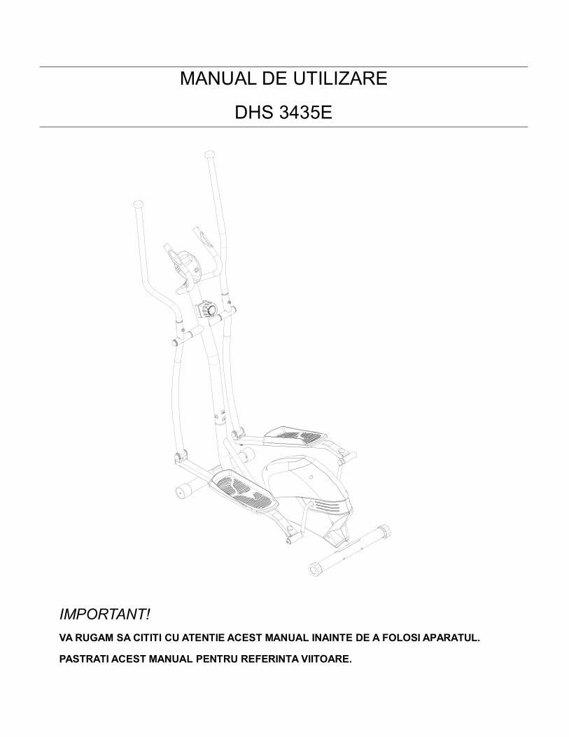
MANUAL DE UTILIZARE
DHS 3435E
IMPORTANT!VARUGAM SACITITI CU ATENTIE ACEST MANUAL INAINTE DE A FOLOSI APARATUL.
PASTRATI ACEST MANUAL PENTRU REFERINTA VIITOARE.
1
Instructiuni Importante de Siguranta
Va multumim ca ati ales acest produs. Pentru a va garanta siguranta si sanatatea dumneavoastra,va rugam sa folositi corect aparatul. Va rugam sa cititi cu atentie acest manual inainte de a folosiaparatul.
1. Este important sa cititi intregul manual inainte de a incepe asamblarea si de a folosi aparatul.Aparatul poate fi folosit in siguranta si eficient doar daca acesta a fost asamblat, intretinut sifolosit adecvat. Este responsabilitatea dumneavoastra sa va asigurati ca toti utilizatoriiaparatului au fost informati cu privire la atentionarile si precautile care trebuie respectate.
2. Inainte de a incepe antrenamentul, consultati doctorul pentru a va asigura ca nu aveti nici oproblema medicala sau fizica care ar putea sa va puna in pericol sanatatea si siguranta saucare ar putea sa va impiedice sa folositi corect aparatul. Urmati sfaturile doctorului dacasunteti sub tratament care va poate afecta ritmul batailor inimii, tensiunea sau nivelulcolesterolului.
3. Tineti cont de semnalele transmise de organism. Efectuarea de exercitii incorecte sauexcesive va poate afecta sanatatea. Intrerupeti antrenamentul daca aveti oricare dintresimptomele: durere in piept, respiratie neregulata, intreruperea respiratiei, ameteala saugreata. In acest caz trebuie sa consultati doctorul inainte de a va continua antrenamentul.
4. Nu lasati copiii sau animalele in preajma aparatului. Acest aparat a fost creat pentru a fi folositdoar de catre adulti.
5. Asezati aparatul pe o suprafata solida, plana, acoperita pentru a va proteja podeaua saucovorul. Pentru a fi in siguranta, asigurati-va ca pastrati o distanta minima de 0.6 m in jurulaparatului.
6. Inainte de a incepe antrenamentul, verificati daca toate piesele: suruburi, piulite si saibe, suntfixate si stranse corect. Daca auziti vreun zgomot in timpul asamblarii sau a utilizarii, incheiatiantrenamentul imediat. Nu folositi aparatul pana cand nu a fost remediata problema.
7. Computerul are multe functii, iar valorile acestora vor fi afisate in functie de tipul exercitiului, vareamintim ca valoarea pulsului nu poate fi folosita pentru diagnosticare, ci este doar orientativa.
8. Purtati haine si incaltaminte adecvata pentru antrenament. Evitati purtarea hainelor largi cares-ar putea agata de aparat sau care v-ar putea restrictiona sau impiedica miscarea.
9. Acest aparat a fost conceput pentru a fi folosit acasa si in spatiu interior. Greutatea maximapermisa a utilizatorului este 120 KG.
10. Aveti grija sa nu va afectati spatele atunci cand ridicati sau mutati aparatul.11. Acest produs nu este potrivit pentru a fi folosit in scop terapeutic.12. Va rugam sa pastrati aceste instructiuni si uneltele de asamblare pentru a le avea la indemana.
2
LISTAPARTILOR COMPONENTE:
2
3
4
4
56 7
8
1423 9
10
12
13R
14
12
13L
15
16
24
2223
21
17 1918
20
31
34
3738
56
17
63
43L
3
44
45
4746
4950
31
32
33
33
3738
20
21
242322
21
52A53
29
25R11
60
60
41
60
61
30 36
21
60
60
70
39
39
3233
33
35
25L
41
41
60
6148
4946
4670
40
17
63
41
44
62
56
63
34
16
6243L
43R
55
55
64
54
54
54
54
35
47
66 67 68 69
1
71
2627
28
2851
51
65
1929
19
29
5758
59
2919
17
1918
42
26
56
5329
52B
6356
3738
37
38
56

3
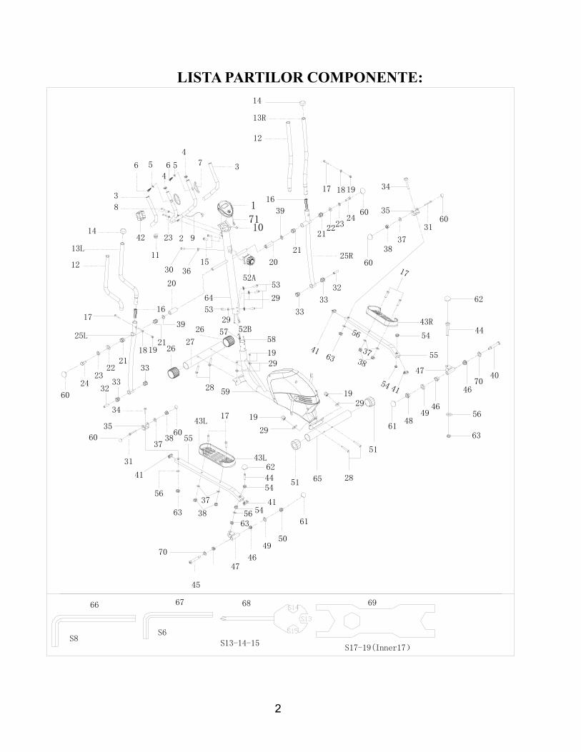
LISTA PARTILOR COMPONENTE:
NR. Descriere Buc NR. Descriere Buc
1 Computer 1 31 Bolt M8*65*30*S14 2
2 Ghidon 1 32 Distantier 14*8.3*48 2
3 Maner ghidon 23*5*445 2 33 Protectie aluminiu 132*3*28*16*14
4
4 Dop rotund 25*16 2 34 Bolt M10*42*20*S17 2
5 Saiba d6*Φ12*1 2 35 Connector sub forma de U 2
6 Surub ST4*19 2 36 Saiba arc d6*Φ20*1.5*R30 1
7 Zona puls maner *25 2 37 Saiba d8*Φ16*1.5 6
8 Surub M8*30*S6 2 38 Piulita nylon M8*H7.5*S13 6
9 Fire puls maner 1 39 Saiba valurita d19*Φ25*0.3 2
10 Fire superioare senzor 1 40 Bolt de prindere - dreaptaΦ16*89*23*1/2*S8
1
11 Surub 12*11*Φ3 1 41 Dop J40*25*15 4
12 Protectie maner 26*5*510 2 42 Capac clema 1
13L/R Ghidon St./Dr. 2 43L/R Pedale St./Dr. 2
14 Dop 28*32*50 2 44 Bolt M10*50*13*S17 2
15 Surub M5*10 2 45 Bolt de prindere - stangaΦ16*89*23*1/2*S8
1
16 Bucsa 32*25*L83 2 46 Bucsa de aluminiu28*4*Φ24*12*16.1
4
17 Bolt M8*40*20*S14 Tip A 6 47 Conector 2
18 Saiba arc d8*Φ20*2*R16 2 48 Piulita Nylon dreapta1/2*20*H8*S19
1
19 Piulita M8*H16*S13 6 49 Saiba arc 1/2” 2
20 Distantier lung 32*19.2*75.5 2 50 Piulita Nylon stanga1/2*20*H8*S19
1
21 Protectie aluminiu 2 *32 4 51 Dop 50*45.5*64.5 2
22 Saiba d8*Φ32*2 2 52A Reglaj tensiune 1
4
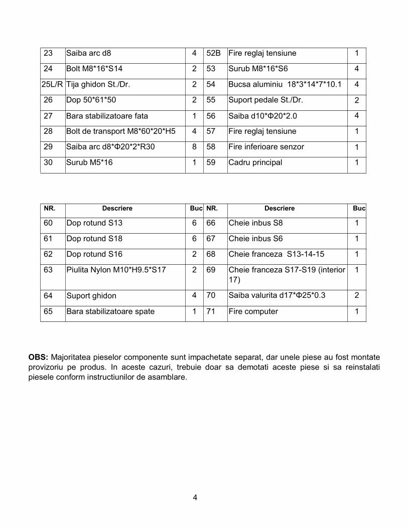
OBS: Majoritatea pieselor componente sunt impachetate separat, dar unele piese au fost montateprovizoriu pe produs. In aceste cazuri, trebuie doar sa demotati aceste piese si sa reinstalatipiesele conform instructiunilor de asamblare.
23 Saiba arc d8 4 52B Fire reglaj tensiune 1
24 Bolt M8*16*S14 2 53 Surub M8*16*S6 4
25L/R Tija ghidon St./Dr. 2 54 Bucsa aluminiu 18*3*14*7*10.1 4
26 Dop 50*61*50 2 55 Suport pedale St./Dr. 2
27 Bara stabilizatoare fata 1 56 Saiba d10*Φ20*2.0 4
28 Bolt de transport M8*60*20*H5 4 57 Fire reglaj tensiune 1
29 Saiba arc d8*Φ20*2*R30 8 58 Fire inferioare senzor 1
30 Surub M5*16 1 59 Cadru principal 1
NR. Descriere Buc NR. Descriere Buc
60 Dop rotund S13 6 66 Cheie inbus S8 1
61 Dop rotund S18 6 67 Cheie inbus S6 1
62 Dop rotund S16 2 68 Cheie franceza S13-14-15 1
63 Piulita Nylon M10*H9.5*S17 2 69 Cheie franceza S17-S19 (interior17)
1
64 Suport ghidon 4 70 Saiba valurita d17*Φ25*0.3 2
65 Bara stabilizatoare spate 1 71 Fire computer 1
5
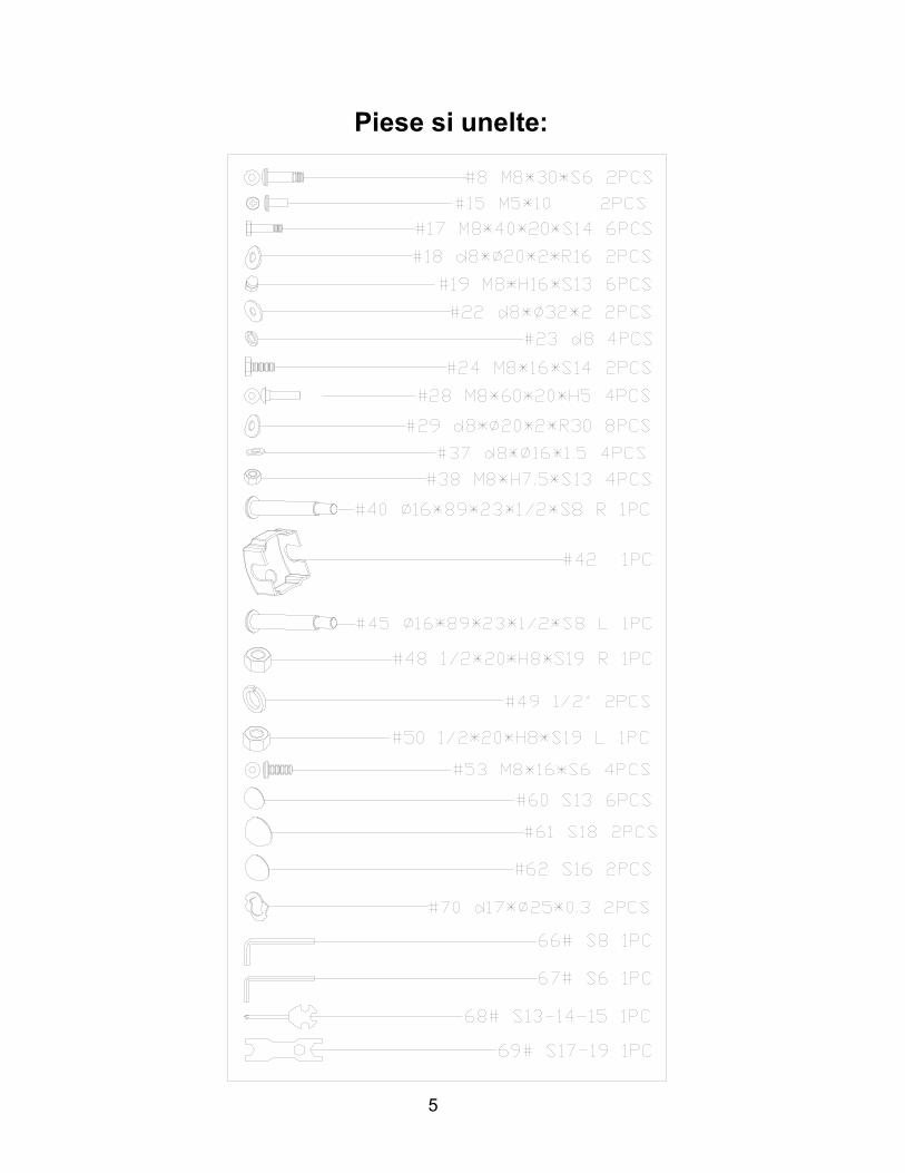
Piese si unelte:
6
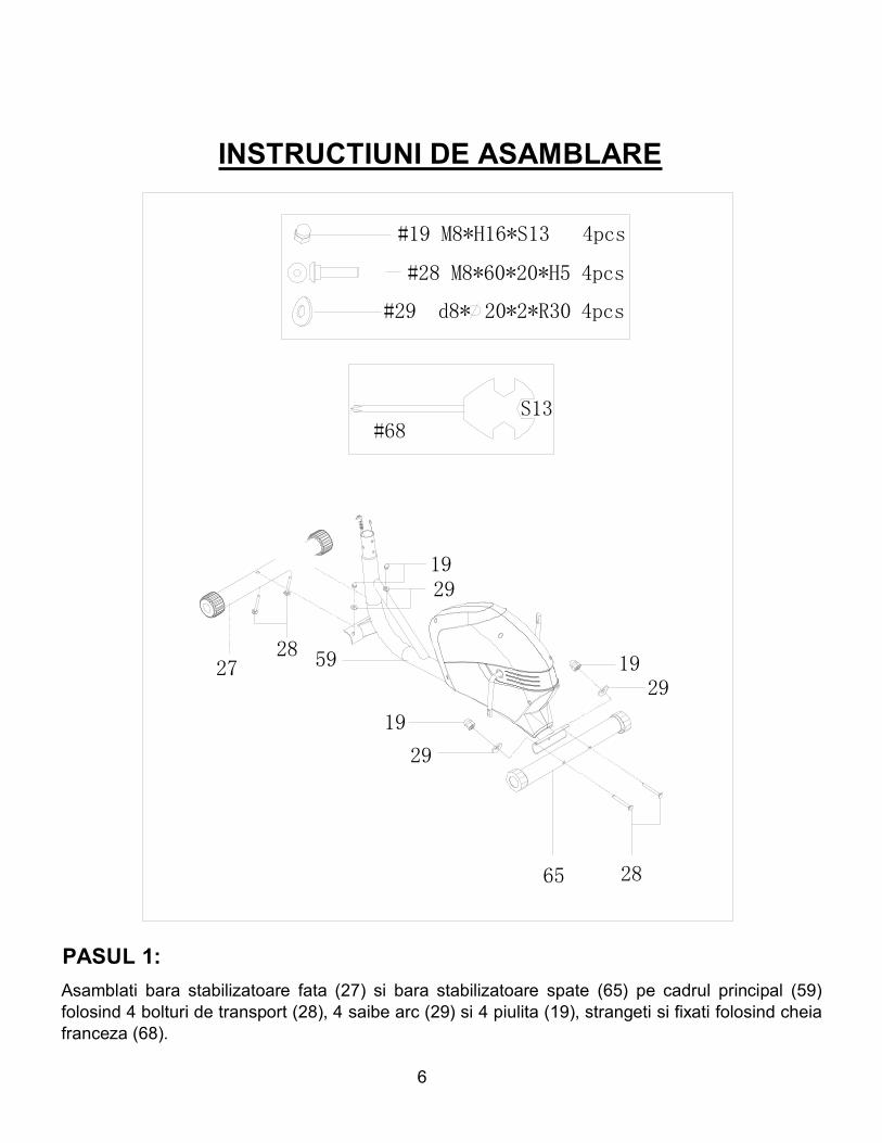
INSTRUCTIUNI DE ASAMBLARE
#28 M8*60*20*H5 4pcs
#29 d8* 20*2*R30 4pcs
#19 M8*H16*S13 4pcs
2728
2865
1929
19
29
59
2919
PASUL 1:Asamblati bara stabilizatoare fata (27) si bara stabilizatoare spate (65) pe cadrul principal (59)folosind 4 bolturi de transport (28), 4 saibe arc (29) si 4 piulita (19), strangeti si fixati folosind cheiafranceza (68).
7
64
29
2953
5329 53
10
52B
5758
S6
#53 M8*16*S6 4PCS
#29 d8* 20*2*R30 4PCS
10
58
57
52B
59
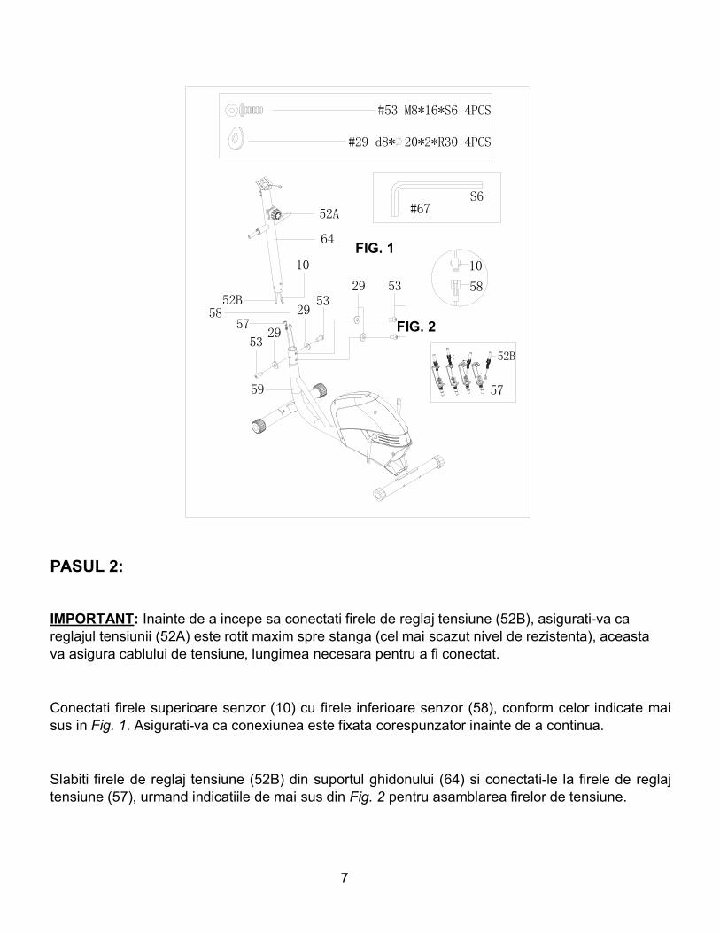
52A #67
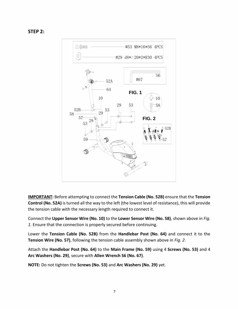
PASUL 2:
IMPORTANT: Inainte de a incepe sa conectati firele de reglaj tensiune (52B), asigurati-va careglajul tensiunii (52A) este rotit maxim spre stanga (cel mai scazut nivel de rezistenta), aceastava asigura cablului de tensiune, lungimea necesara pentru a fi conectat.
Conectati firele superioare senzor (10) cu firele inferioare senzor (58), conform celor indicate maisus in Fig. 1. Asigurati-va ca conexiunea este fixata corespunzator inainte de a continua.
Slabiti firele de reglaj tensiune (52B) din suportul ghidonului (64) si conectati-le la firele de reglajtensiune (57), urmand indicatiile de mai sus din Fig. 2 pentru asamblarea firelor de tensiune.
FIG. 1
FIG. 2
8
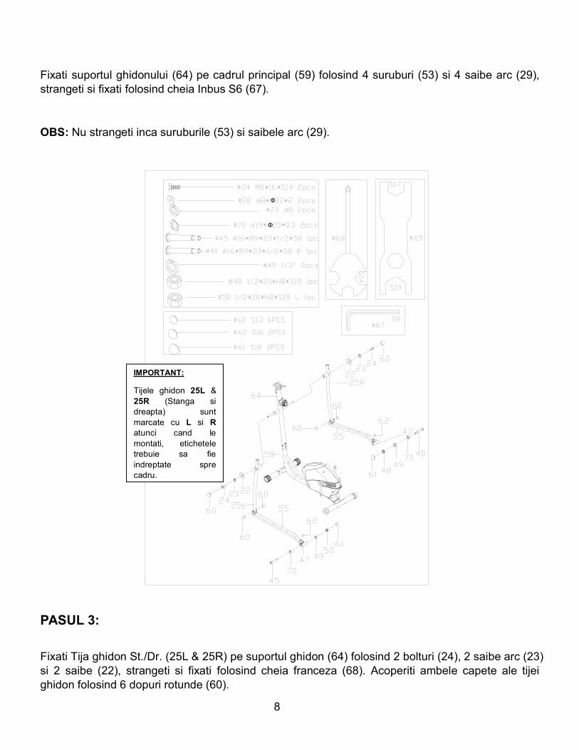
Fixati suportul ghidonului (64) pe cadrul principal (59) folosind 4 suruburi (53) si 4 saibe arc (29),strangeti si fixati folosind cheia Inbus S6 (67).
OBS: Nu strangeti inca suruburile (53) si saibele arc (29).
Φ
Φ
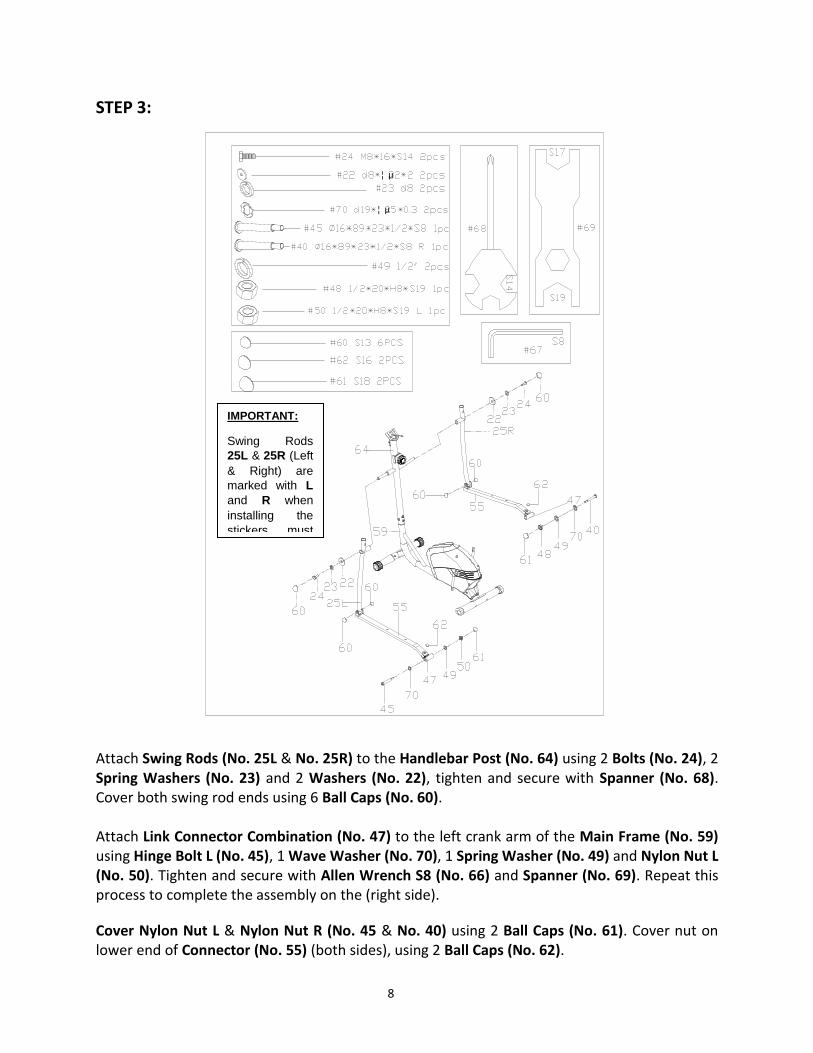
PASUL 3:
Fixati Tija ghidon St./Dr. (25L & 25R) pe suportul ghidon (64) folosind 2 bolturi (24), 2 saibe arc (23)si 2 saibe (22), strangeti si fixati folosind cheia franceza (68). Acoperiti ambele capete ale tijeighidon folosind 6 dopuri rotunde (60).
IMPORTANT:
Tijele ghidon 25L &25R (Stanga sidreapta) suntmarcate cu L si Ratunci cand lemontati, eticheteletrebuie sa fieindreptate sprecadru.
9
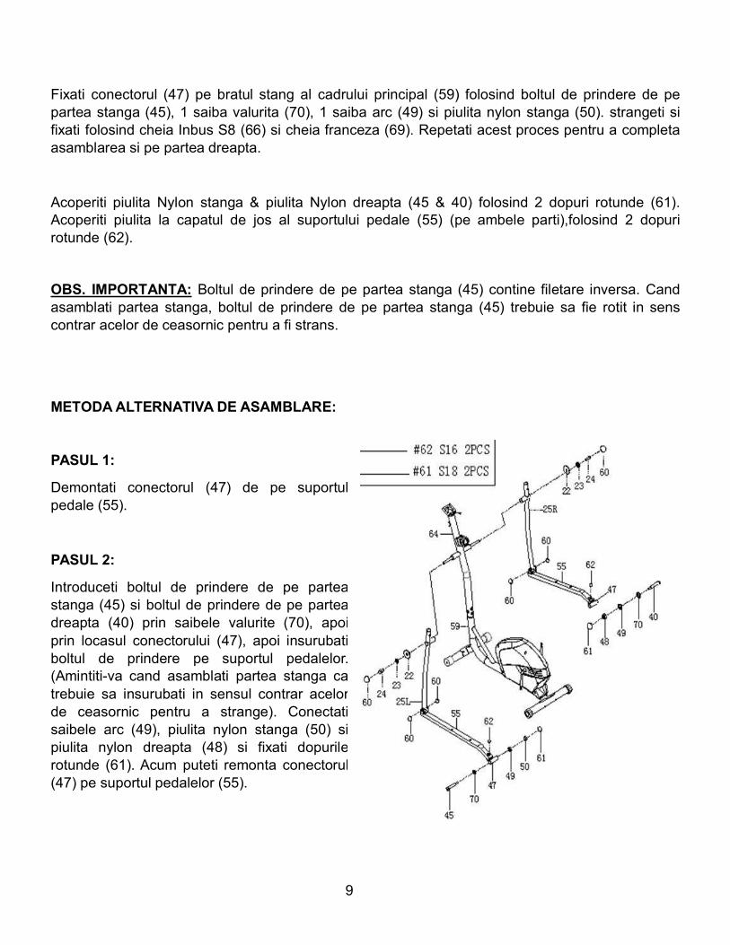
Fixati conectorul (47) pe bratul stang al cadrului principal (59) folosind boltul de prindere de pepartea stanga (45), 1 saiba valurita (70), 1 saiba arc (49) si piulita nylon stanga (50). strangeti sifixati folosind cheia Inbus S8 (66) si cheia franceza (69). Repetati acest proces pentru a completaasamblarea si pe partea dreapta.
Acoperiti piulita Nylon stanga & piulita Nylon dreapta (45 & 40) folosind 2 dopuri rotunde (61).Acoperiti piulita la capatul de jos al suportului pedale (55) (pe ambele parti),folosind 2 dopurirotunde (62).
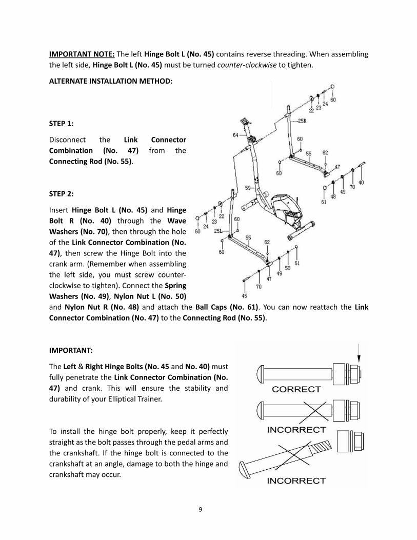
OBS. IMPORTANTA: Boltul de prindere de pe partea stanga (45) contine filetare inversa. Candasamblati partea stanga, boltul de prindere de pe partea stanga (45) trebuie sa fie rotit in senscontrar acelor de ceasornic pentru a fi strans.
METODAALTERNATIVA DE ASAMBLARE:
PASUL 1:
Demontati conectorul (47) de pe suportulpedale (55).
PASUL 2:
Introduceti boltul de prindere de pe parteastanga (45) si boltul de prindere de pe parteadreapta (40) prin saibele valurite (70), apoiprin locasul conectorului (47), apoi insurubatiboltul de prindere pe suportul pedalelor.(Amintiti-va cand asamblati partea stanga catrebuie sa insurubati in sensul contrar acelorde ceasornic pentru a strange). Conectatisaibele arc (49), piulita nylon stanga (50) sipiulita nylon dreapta (48) si fixati dopurilerotunde (61). Acum puteti remonta conectorul(47) pe suportul pedalelor (55).
10
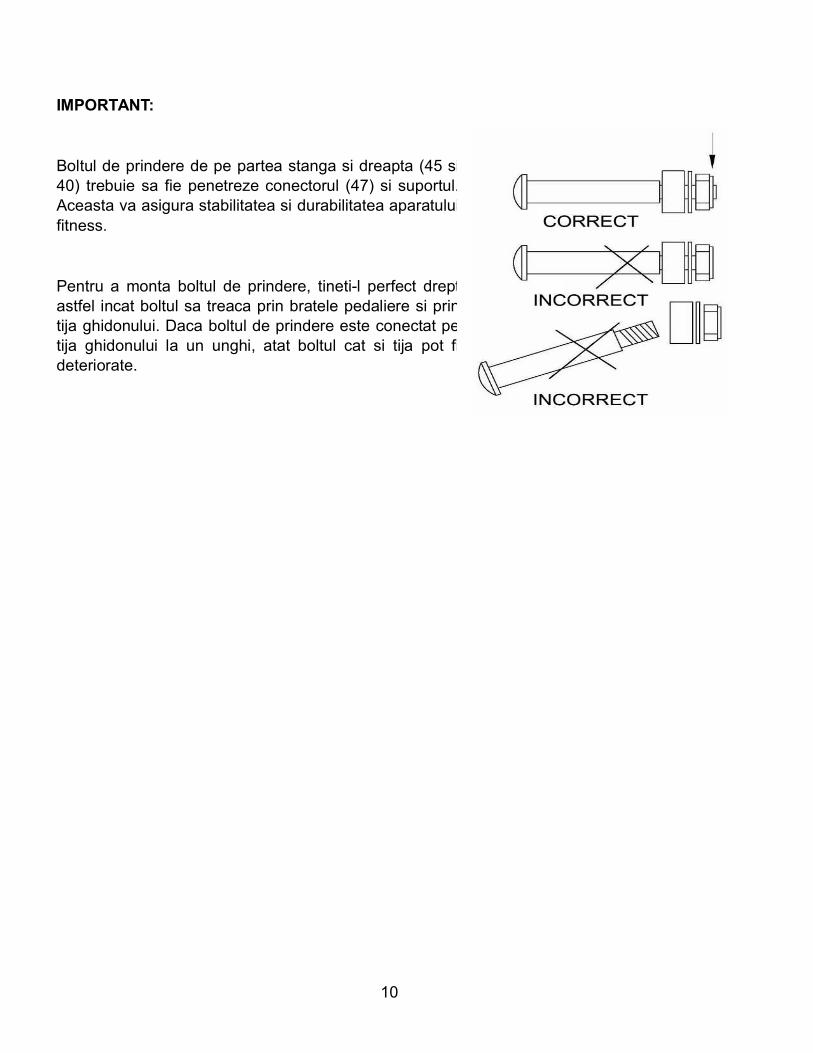
IMPORTANT:
Boltul de prindere de pe partea stanga si dreapta (45 si40) trebuie sa fie penetreze conectorul (47) si suportul.Aceasta va asigura stabilitatea si durabilitatea aparatuluifitness.
Pentru a monta boltul de prindere, tineti-l perfect dreptastfel incat boltul sa treaca prin bratele pedaliere si printija ghidonului. Daca boltul de prindere este conectat petija ghidonului la un unghi, atat boltul cat si tija pot fideteriorate.
11
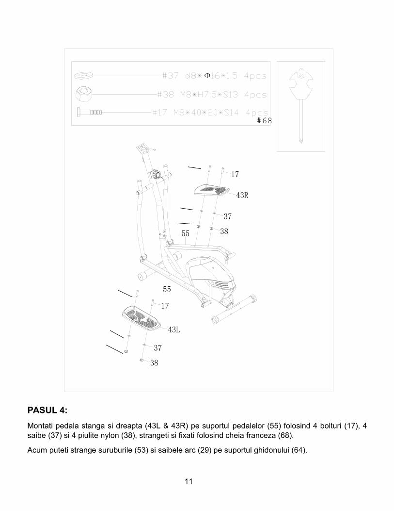
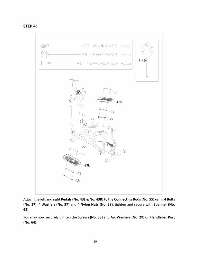
PASUL 4:Montati pedala stanga si dreapta (43L & 43R) pe suportul pedalelor (55) folosind 4 bolturi (17), 4saibe (37) si 4 piulite nylon (38), strangeti si fixati folosind cheia franceza (68).
Acum puteti strange suruburile (53) si saibele arc (29) pe suportul ghidonului (64).
Φ
55
43L
17
55
37
38
43R
17
37
38
#68
12
#17 M8*40*20*S14 2PCS
#18 d8*Φ20*2*R16 2PCS
#19 M8*H16*S13 2PCS
13L
13R
18
17
1918
25L
25R
19
17
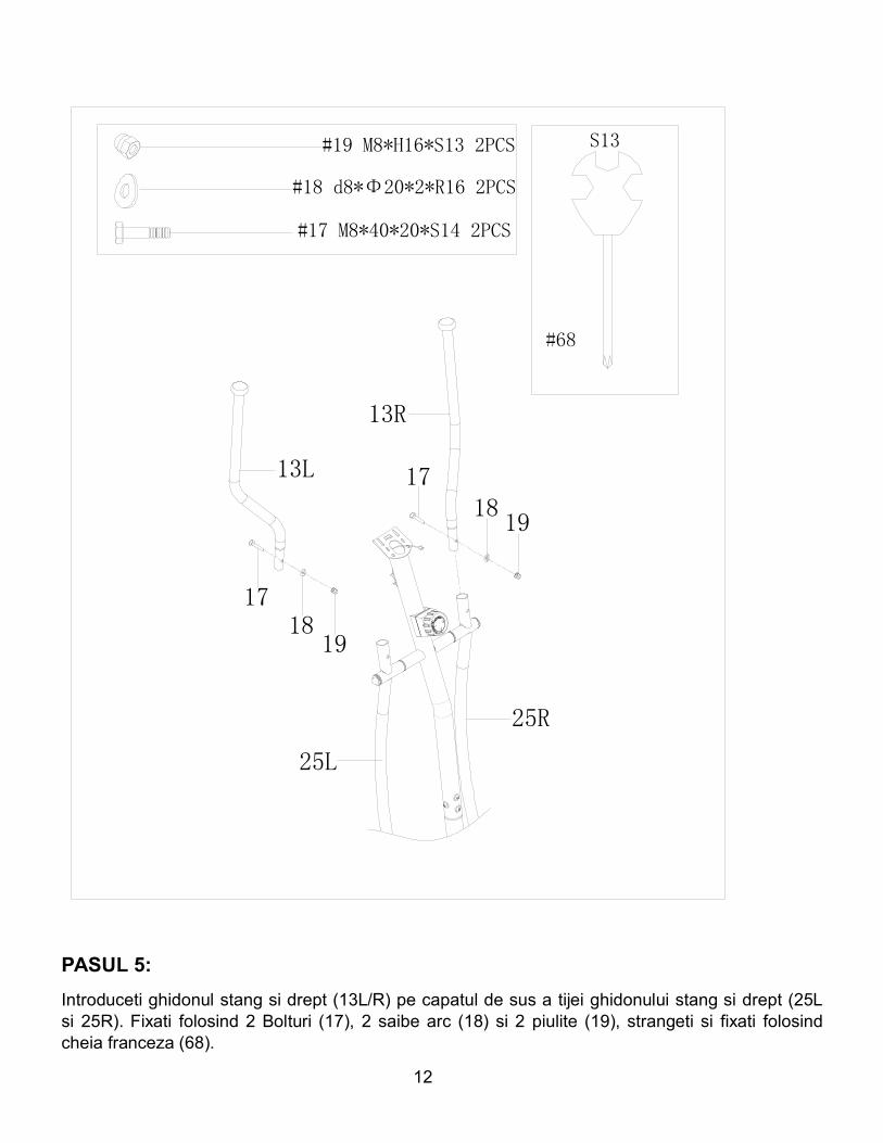
PASUL 5:Introduceti ghidonul stang si drept (13L/R) pe capatul de sus a tijei ghidonului stang si drept (25Lsi 25R). Fixati folosind 2 Bolturi (17), 2 saibe arc (18) si 2 piulite (19), strangeti si fixati folosindcheia franceza (68).
13
#15 M5*10 2PCS
223
15
8
109
#23 d8 2PCS
#8 M8*30*S6 2PCS
171
64
42
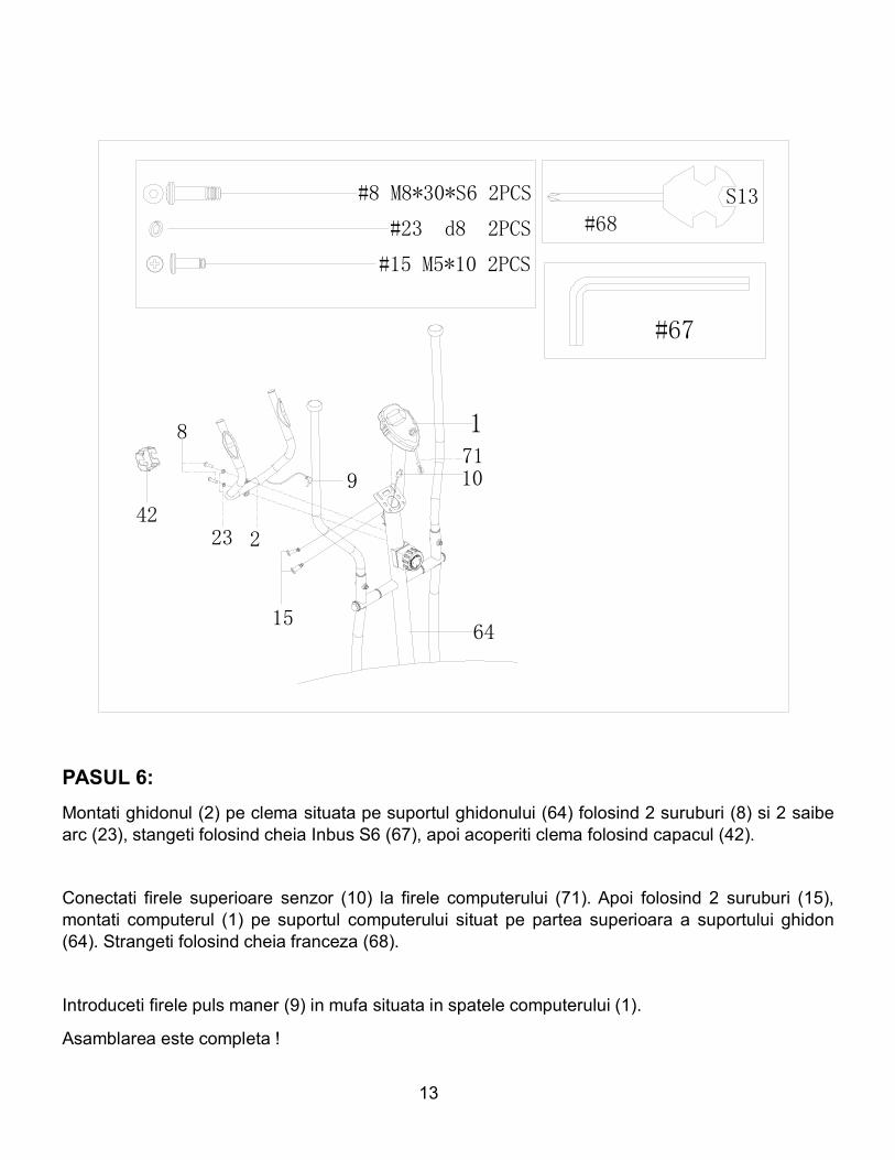
PASUL 6:Montati ghidonul (2) pe clema situata pe suportul ghidonului (64) folosind 2 suruburi (8) si 2 saibearc (23), stangeti folosind cheia Inbus S6 (67), apoi acoperiti clema folosind capacul (42).
Conectati firele superioare senzor (10) la firele computerului (71). Apoi folosind 2 suruburi (15),montati computerul (1) pe suportul computerului situat pe partea superioara a suportului ghidon(64). Strangeti folosind cheia franceza (68).
Introduceti firele puls maner (9) in mufa situata in spatele computerului (1).
Asamblarea este completa !

14
FUNCTIILE COMPUTERULUI
Consola computerizata a bicicletei fitness permite utilizatorului sa isi construiasca un antrenamentpersonalizat prin monitorizarea progreselor. In timpul antrenamentului, consola va afisa alternativsi repetitiv: Timpul, Viteza, Distanta, Caloriile si Pulsul. Prin intermediul consolei usor de utilizat,utilizatorul isi poate urmari eficient progresele realizate de la un antrenament fitness la urmatorulantrenament.
FUNCTII BUTOANE:1. MOD: Pentru a selecta functia dorita si/sau sa porniti consola.
FUNCTII SI SPECIFICATII:1. SCAN – Scaneaza automat toate functiile (in ordinea urmatoare)
2. TIMP (TIME) -- Memorează automat timpul antrenamentului (pana la 99:59 MIN).
3. VITEZA (SPEED) -- Afiseaza viteza curenta (de la 00.00 pana la 999.9 KM/H sau MPH).
4. DISTANTA (DISTANCE) – Calculeaza distanta parcursa in timpul antrenamentului (0.00-999.99 KM / Mile).
5. CALORII (CALORIES) – Calculeaza caloriile consumate pe ora (0.0-999.9 KCAL).
6. PULS (PULSE) – Afiseaza bataile inimii pe minut in timpul antrenamentului. (40-240 BPM)*Pentru a va masura bataile inimii, asezati-va palmele mainilor pe ambele protectii aleghidonului.
PROCEDURI DE OPERARE:
1. AUTO ON/OFF:
Incepeti pedalarea sau apasati butonul MODE pentru a porni consola. De indata de consola estepornita, aceasta va ramane activa pe perioada antrenamentului. Daca timp de 4 minute aparatulnu primeste vreun semnal, acesta se va inchide automat.
2. RESET:
15
Tineti apasat butonul MODE pentru 3 secunde pentru a reseta consola. Puteti reseta consola siprin scoaterea bateriilor.
3. MODUL DE BLOCARE:In MODUL BLOCARE, consola va afisa doar statistica dorita. Pentru a selecta MODUL DEBLOCARE, apasati butonul MODE cand cursorul este pe functia pe care doriti sa o selectati.
4. BATTERII / REZOLVAREA PROBLEMELOR: Acest monitor foloseste doua baterii de tip „AA”.Daca consola nu este clara sau este greu de citit valorile, inlocuiti ambele baterii inainte de acontacta Serviciul clienti.
16
INSTRUCTIUNI EXERCITII DE INCALZIRE
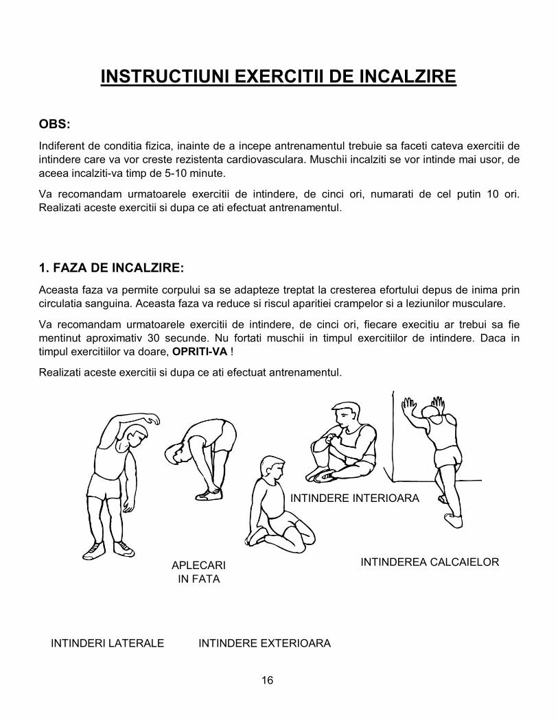
OBS:Indiferent de conditia fizica, inainte de a incepe antrenamentul trebuie sa faceti cateva exercitii deintindere care va vor creste rezistenta cardiovasculara. Muschii incalziti se vor intinde mai usor, deaceea incalziti-va timp de 5-10 minute.
Va recomandam urmatoarele exercitii de intindere, de cinci ori, numarati de cel putin 10 ori.Realizati aceste exercitii si dupa ce ati efectuat antrenamentul.
1. FAZA DE INCALZIRE:Aceasta faza va permite corpului sa se adapteze treptat la cresterea efortului depus de inima princirculatia sanguina. Aceasta faza va reduce si riscul aparitiei crampelor si a leziunilor musculare.
Va recomandam urmatoarele exercitii de intindere, de cinci ori, fiecare execitiu ar trebui sa fiementinut aproximativ 30 secunde. Nu fortati muschii in timpul exercitiilor de intindere. Daca intimpul exercitiilor va doare, OPRITI-VA !
Realizati aceste exercitii si dupa ce ati efectuat antrenamentul.
I INTINDEREA CALCAIELORAPLECARIIN FATA
INTINDERE INTERIOARA
INTINDERI LATERALE INTINDERE EXTERIOARA
17
2.FAZA DE REPAUS:Aceasta faza va permite sistemului cardiovascular si muschilor sa se refaca. Incepeti prin a reduceritmul exercitiilor si sa continuati pentru aproximativ 5 minute. Apoi, repetati faza de incalzire prinreluarea exercitiilor de intindere, si aveti grija sa nu va fortati muschii printr-o intindere !
Pe masura ce va creste rezistenta, va fi necesar sa va antrenati mai mult. Va recomandam sa vaantrenati de cel putin trei ori pe saptamana, si daca este posibil, sa aveti perioade de timp egaleintre antrenamente.
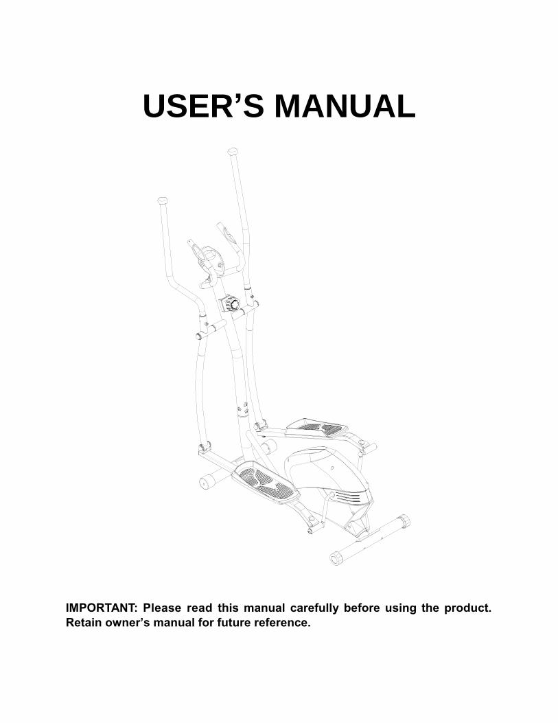
USER’S MANUAL
IMPORTANT: Please read this manual carefully before using the product.
Retain owner’s manual for future reference.

1
IMPORTANT SAFETY INFORMATION We thank you for choosing our product. To ensure your safety and health, please use this equipment correctly. It is important to read this entire manual before assembling and using the equipment. Safe and effective use can only be achieved if the equipment is assembled, maintained and used properly. It is your responsibility to ensure that all users of the equipment are informed of all warnings and precautions. 1. Before starting any exercise program you should consult your physician to determine if you
have any medical or physical conditions that could put your health and safety at risk, or prevent you from using the equipment properly. Your physician’s advice is essential if you are taking medication that affects your heart rate, blood pressure or cholesterol level.
2. Be aware of your body’s signals. Incorrect or excessive exercise can damage your health. Stop exercising if you experience any of the following symptoms: pain, tightness in your chest, irregular heartbeat, and extreme shortness of breath, lightheadedness, dizziness or feelings of nausea. If you do experience any of these conditions, you should consult your physician before continuing with your exercise program.
3. Keep children and pets away from the equipment. The equipment is designed for adult use only.
4. Use the equipment on a solid, flat level surface with a protective cover for your floor or carpet. To ensure safety, the equipment should have at least 2 feet of free space all around it.
5. Ensure that all nuts and bolts are securely tightened before using the equipment. The safety of the equipment can only be maintained if it is regularly examined for damage and/or wear and tear.
6. It is recommended that you lubricate all moving parts on a monthly basis. 7. Always use the equipment as indicated. If you find any defective components while
assembling or checking the equipment, or if you hear any unusual noises coming from the equipment during exercise, stop using the equipment immediately and don’t use the equipment until the problem has been rectified.
8. Wear suitable clothing while using the equipment. Avoid wearing loose clothing that may become entangled in the equipment.
9. Do not place fingers or objects into moving parts of the exercise equipment. 10. The maximum weight capacity of this unit is 110 KG. 11. The equipment is not suitable for therapeutic use. 12. You must take care of yourself when lifting and moving the equipment so as not to injure your
back. Always use proper lifting technique and seek assistance if necessary. 13. This equipment is designed for indoor and home use only! It is not intended for commercial
use!
2
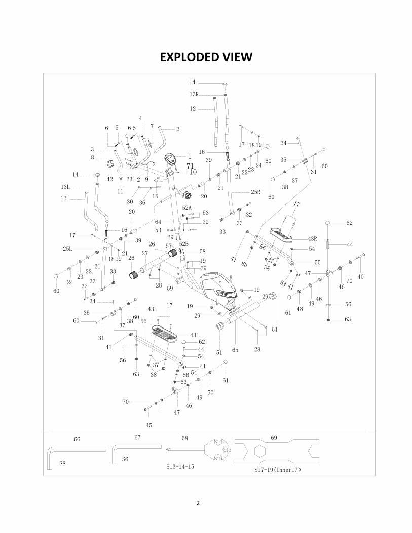
EXPLODED VIEW
2
3
4
4
56 7
8
1423 9
10
12
13R
14
12
13L
15
16
24
2223
21
17 1918
20
31
34
3738
56
17
63
43L
3
44
45
4746
4950
31
32
33
33
3738
20
21
242322
21
52A53
29
25R11
60
60
41
60
61
30 36
21
60
60
70
39
39
3233
33
35
25L
41
41
60
6148
4946
4670
40
17
63
41
44
62
56
63
34
16
6243L
43R
55
55
64
54
54
54
54
35
47
66 67 68 69
1
71
2627
28
2851
51
65
1929
19
29
5758
59
2919
17
1918
42
26
56
5329
52B
6356
3738
37
38
56
3
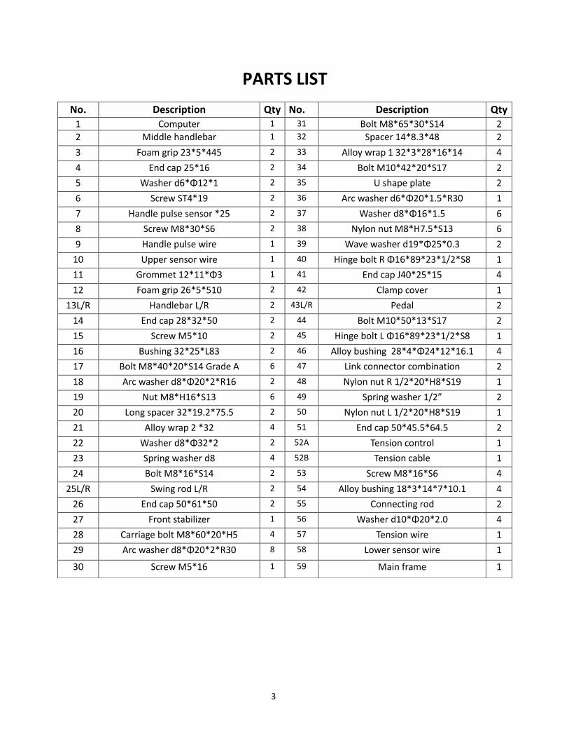
PARTS LIST
No. Description Qty No. Description Qty
1 Computer 1 31 Bolt M8*65*30*S14 2
2 Middle handlebar 1 32 Spacer 14*8.3*48 2
3 Foam grip 23*5*445 2 33 Alloy wrap 1 32*3*28*16*14 4
4 End cap 25*16 2 34 Bolt M10*42*20*S17 2
5 Washer d6*Φ12*1 2 35 U shape plate 2
6 Screw ST4*19 2 36 Arc washer d6*Φ20*1.5*R30 1
7 Handle pulse sensor *25 2 37 Washer d8*Φ16*1.5 6
8 Screw M8*30*S6 2 38 Nylon nut M8*H7.5*S13 6
9 Handle pulse wire 1 39 Wave washer d19*Φ25*0.3 2
10 Upper sensor wire 1 40 Hinge bolt R Φ16*89*23*1/2*S8 1
11 Grommet 12*11*Φ3 1 41 End cap J40*25*15 4
12 Foam grip 26*5*510 2 42 Clamp cover 1
13L/R Handlebar L/R 2 43L/R Pedal 2
14 End cap 28*32*50 2 44 Bolt M10*50*13*S17 2
15 Screw M5*10 2 45 Hinge bolt L Φ16*89*23*1/2*S8 1
16 Bushing 32*25*L83 2 46 Alloy bushing 28*4*Φ24*12*16.1 4
17 Bolt M8*40*20*S14 Grade A 6 47 Link connector combination 2
18 Arc washer d8*Φ20*2*R16 2 48 Nylon nut R 1/2*20*H8*S19 1
19 Nut M8*H16*S13 6 49 Spring washer 1/2” 2
20 Long spacer 32*19.2*75.5 2 50 Nylon nut L 1/2*20*H8*S19 1
21 Alloy wrap 2 *32 4 51 End cap 50*45.5*64.5 2
22 Washer d8*Φ32*2 2 52A Tension control 1
23 Spring washer d8 4 52B Tension cable 1
24 Bolt M8*16*S14 2 53 Screw M8*16*S6 4
25L/R Swing rod L/R 2 54 Alloy bushing 18*3*14*7*10.1 4
26 End cap 50*61*50 2 55 Connecting rod 2
27 Front stabilizer 1 56 Washer d10*Φ20*2.0 4
28 Carriage bolt M8*60*20*H5 4 57 Tension wire 1
29 Arc washer d8*Φ20*2*R30 8 58 Lower sensor wire 1
30 Screw M5*16 1 59 Main frame 1
4
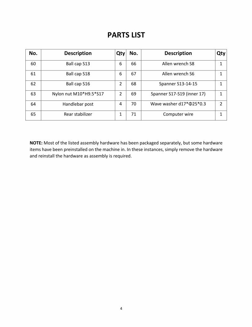
PARTS LIST
NOTE: Most of the listed assembly hardware has been packaged separately, but some hardware
items have been preinstalled on the machine in. In these instances, simply remove the hardware
and reinstall the hardware as assembly is required.
No. Description Qty No. Description Qty
60 Ball cap S13 6 66 Allen wrench S8 1
61 Ball cap S18 6 67 Allen wrench S6 1
62 Ball cap S16 2 68 Spanner S13-14-15 1
63 Nylon nut M10*H9.5*S17 2 69 Spanner S17-S19 (inner 17) 1
64 Handlebar post 4 70 Wave washer d17*Φ25*0.3 2
65 Rear stabilizer 1 71 Computer wire 1
5
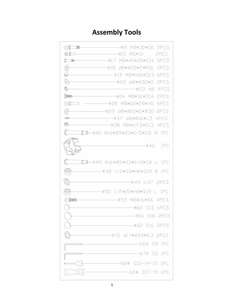
Assembly Tools
6
ASSEMBLY INSTRUCTIONS
#28 M8*60*20*H5 4pcs
#29 d8* 20*2*R30 4pcs
#19 M8*H16*S13 4pcs
2728
2865
1929
19
29
59
2919
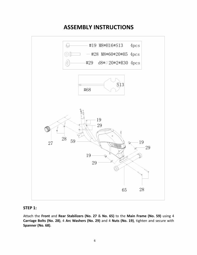
STEP 1:
Attach the Front and Rear Stabilizers (No. 27 & No. 65) to the Main Frame (No. 59) using 4 Carriage Bolts (No. 28), 4 Arc Washers (No. 29) and 4 Nuts (No. 19), tighten and secure with Spanner (No. 68).
7
STEP 2:
64
29
2953
5329 53
10
52B
5758
S6
#53 M8*16*S6 4PCS
#29 d8* 20*2*R30 4PCS
10
58
57
52B
59
52A #67
IMPORTANT: Before attempting to connect the Tension Cable (No. 52B) ensure that the Tension
Control (No. 52A) is turned all the way to the left (the lowest level of resistance), this will provide
the tension cable with the necessary length required to connect it.
Connect the Upper Sensor Wire (No. 10) to the Lower Sensor Wire (No. 58), shown above in Fig.
1. Ensure that the connection is properly secured before continuing.
Lower the Tension Cable (No. 52B) from the Handlebar Post (No. 64) and connect it to the
Tension Wire (No. 57), following the tension cable assembly shown above in Fig. 2.
Attach the Handlebar Post (No. 64) to the Main Frame (No. 59) using 4 Screws (No. 53) and 4
Arc Washers (No. 29), secure with Allen Wrench S6 (No. 67).
NOTE: Do not tighten the Screws (No. 53) and Arc Washers (No. 29) yet.
FIG. 1
FIG. 2
8
STEP 3:
¦ µ
¦ µ
Attach Swing Rods (No. 25L & No. 25R) to the Handlebar Post (No. 64) using 2 Bolts (No. 24), 2 Spring Washers (No. 23) and 2 Washers (No. 22), tighten and secure with Spanner (No. 68). Cover both swing rod ends using 6 Ball Caps (No. 60). Attach Link Connector Combination (No. 47) to the left crank arm of the Main Frame (No. 59) using Hinge Bolt L (No. 45), 1 Wave Washer (No. 70), 1 Spring Washer (No. 49) and Nylon Nut L (No. 50). Tighten and secure with Allen Wrench S8 (No. 66) and Spanner (No. 69). Repeat this process to complete the assembly on the (right side).
Cover Nylon Nut L & Nylon Nut R (No. 45 & No. 40) using 2 Ball Caps (No. 61). Cover nut on lower end of Connector (No. 55) (both sides), using 2 Ball Caps (No. 62).
IMPORTANT:
Swing Rods
25L & 25R (Left
& Right) are
marked with L
and R when
installing the
stickers must
face the frame
9
IMPORTANT NOTE: The left Hinge Bolt L (No. 45) contains reverse threading. When assembling
the left side, Hinge Bolt L (No. 45) must be turned counter-clockwise to tighten.
ALTERNATE INSTALLATION METHOD:
STEP 1:
Disconnect the Link Connector
Combination (No. 47) from the
Connecting Rod (No. 55).
STEP 2:
Insert Hinge Bolt L (No. 45) and Hinge
Bolt R (No. 40) through the Wave
Washers (No. 70), then through the hole
of the Link Connector Combination (No.
47), then screw the Hinge Bolt into the
crank arm. (Remember when assembling
the left side, you must screw counter-
clockwise to tighten). Connect the Spring
Washers (No. 49), Nylon Nut L (No. 50)
and Nylon Nut R (No. 48) and attach the Ball Caps (No. 61). You can now reattach the Link
Connector Combination (No. 47) to the Connecting Rod (No. 55).
IMPORTANT:
The Left & Right Hinge Bolts (No. 45 and No. 40) must
fully penetrate the Link Connector Combination (No.
47) and crank. This will ensure the stability and
durability of your Elliptical Trainer.
To install the hinge bolt properly, keep it perfectly
straight as the bolt passes through the pedal arms and
the crankshaft. If the hinge bolt is connected to the
crankshaft at an angle, damage to both the hinge and
crankshaft may occur.
10
STEP 4:
Attach the left and right Pedals (No. 43L & No. 43R) to the Connecting Rods (No. 55) using 4 Bolts
(No. 17), 4 Washers (No. 37) and 4 Nylon Nuts (No. 38), tighten and secure with Spanner (No.
68).
You may now securely tighten the Screws (No. 53) and Arc Washers (No. 29) on Handlebar Post
(No. 64).
Φ
55
43L
17
55
37
38
43R
17
37
38
#68
11
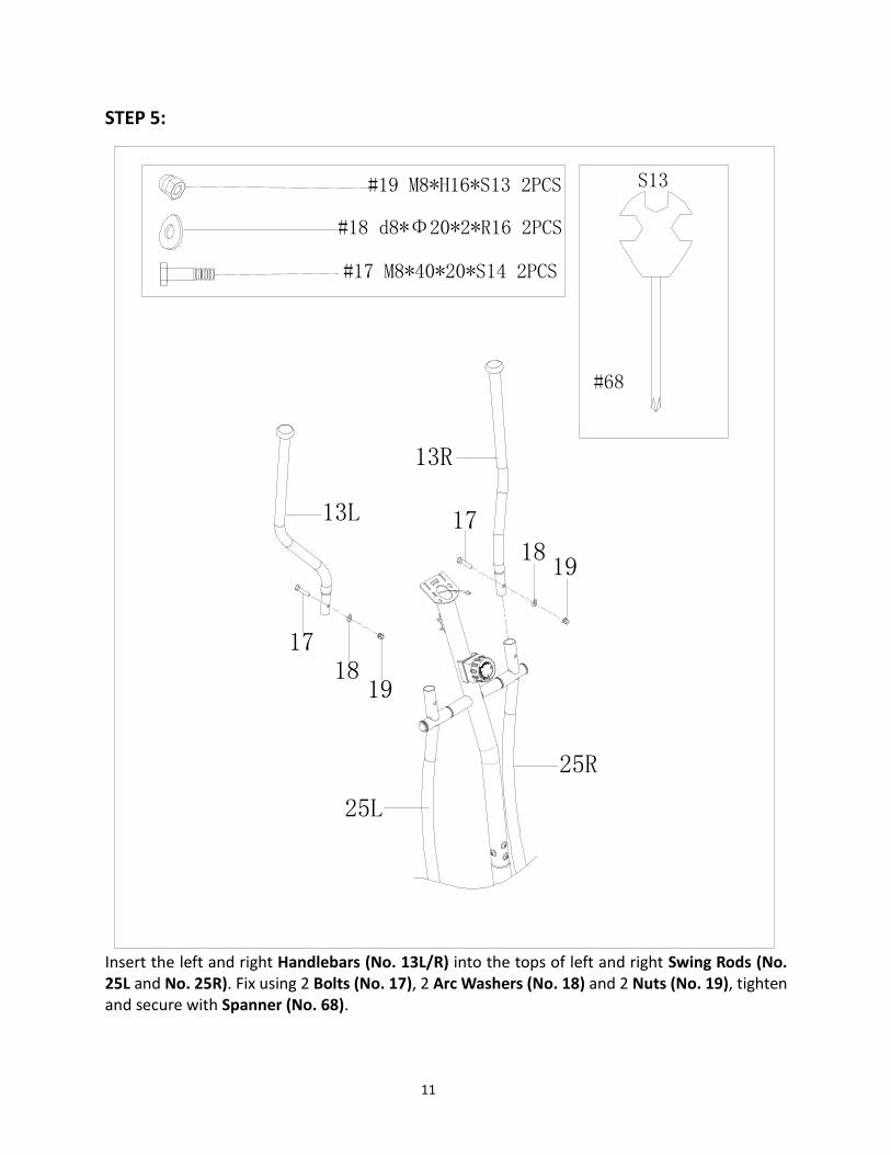
STEP 5:
#17 M8*40*20*S14 2PCS
#18 d8*Φ20*2*R16 2PCS
#19 M8*H16*S13 2PCS
13L
13R
18
17
1918
25L
25R
19
17
Insert the left and right Handlebars (No. 13L/R) into the tops of left and right Swing Rods (No. 25L and No. 25R). Fix using 2 Bolts (No. 17), 2 Arc Washers (No. 18) and 2 Nuts (No. 19), tighten and secure with Spanner (No. 68).
12
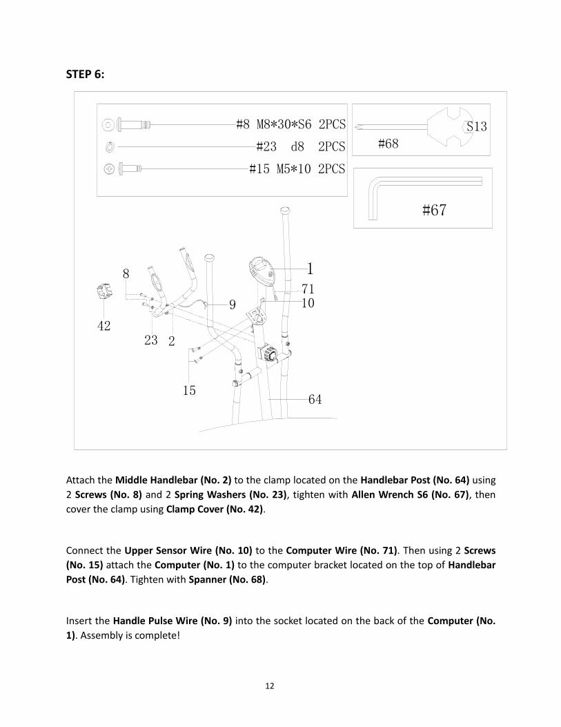
STEP 6:
#15 M5*10 2PCS
223
15
8
109
#23 d8 2PCS
#8 M8*30*S6 2PCS
171
64
42
Attach the Middle Handlebar (No. 2) to the clamp located on the Handlebar Post (No. 64) using
2 Screws (No. 8) and 2 Spring Washers (No. 23), tighten with Allen Wrench S6 (No. 67), then
cover the clamp using Clamp Cover (No. 42).
Connect the Upper Sensor Wire (No. 10) to the Computer Wire (No. 71). Then using 2 Screws
(No. 15) attach the Computer (No. 1) to the computer bracket located on the top of Handlebar
Post (No. 64). Tighten with Spanner (No. 68).
Insert the Handle Pulse Wire (No. 9) into the socket located on the back of the Computer (No.
1). Assembly is complete!
13
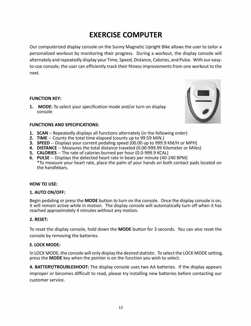
EXERCISE COMPUTER
Our computerized display console on the Sunny Magnetic Upright Bike allows the user to tailor a
personalized workout by monitoring their progress. During a workout, the display console will
alternately and repeatedly display your Time, Speed, Distance, Calories, and Pulse. With our easy-
to-use console, the user can efficiently track their fitness improvements from one workout to the
next.
FUNCTION KEY:
1. MODE: To select your specification mode and/or turn on display console
FUNCTIONS AND SPECIFICATIONS:
1. SCAN – Repeatedly displays all functions alternately (in the following order) 2. TIME -- Counts the total time elapsed (counts up to 99:59 MIN.) 3. SPEED -- Displays your current pedaling speed (00.00 up to 999.9 KM/H or MPH) 4. DISTANCE -- Measures the total distance traveled (0.00-999.99 Kilometer or Miles) 5. CALORIES -- The rate of calories burned per hour (0.0-999.9 KCAL) 6. PULSE -- Displays the detected heart rate in beats per minute (40-240 BPM)
*To measure your heart rate, place the palm of your hands on both contact pads located on the handlebars.
HOW TO USE:
1. AUTO ON/OFF:
Begin pedaling or press the MODE button to turn on the console. Once the display console is on, it will remain active while in motion. The display console will automatically turn off when it has reached approximately 4 minutes without any motion.
2. RESET:
To reset the display console, hold down the MODE button for 3 seconds. You can also reset the
console by removing the batteries.
3. LOCK MODE:
In LOCK MODE, the console will only display the desired statistic. To select the LOCK MODE setting, press the MODE key when the pointer is on the function you wish to select.
4. BATTERY/TROUBLESHOOT: The display console uses two AA batteries. If the display appears
improper or becomes difficult to read, please try installing new batteries before contacting our
customer service.
14
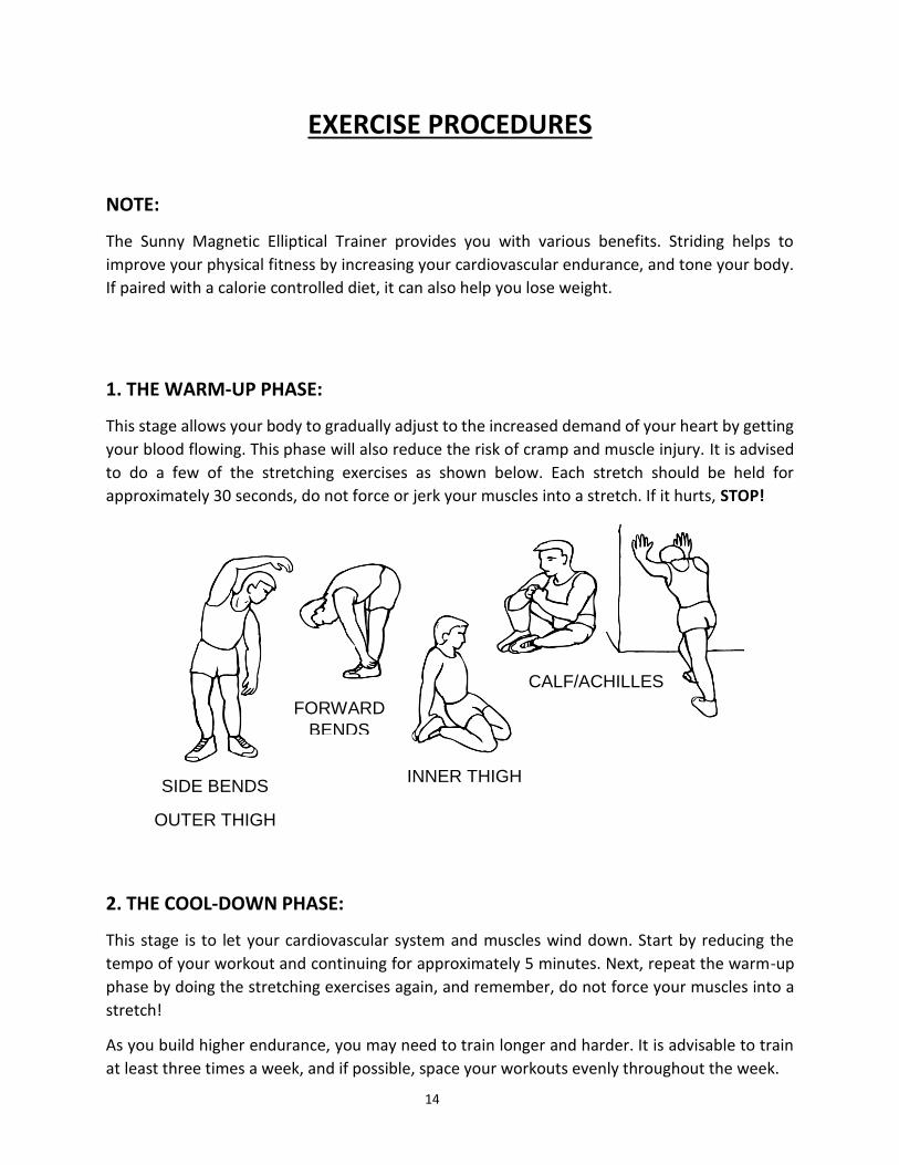
EXERCISE PROCEDURES
NOTE:
The Sunny Magnetic Elliptical Trainer provides you with various benefits. Striding helps to
improve your physical fitness by increasing your cardiovascular endurance, and tone your body.
If paired with a calorie controlled diet, it can also help you lose weight.
1. THE WARM-UP PHASE:
This stage allows your body to gradually adjust to the increased demand of your heart by getting
your blood flowing. This phase will also reduce the risk of cramp and muscle injury. It is advised
to do a few of the stretching exercises as shown below. Each stretch should be held for
approximately 30 seconds, do not force or jerk your muscles into a stretch. If it hurts, STOP!
2. THE COOL-DOWN PHASE:
This stage is to let your cardiovascular system and muscles wind down. Start by reducing the
tempo of your workout and continuing for approximately 5 minutes. Next, repeat the warm-up
phase by doing the stretching exercises again, and remember, do not force your muscles into a
stretch!
As you build higher endurance, you may need to train longer and harder. It is advisable to train
at least three times a week, and if possible, space your workouts evenly throughout the week.
FORWARD
BENDS
SIDE BENDS
OUTER THIGH
INNER THIGH
CALF/ACHILLES