Instrumentele de Zbor Ale Unui Avion
9
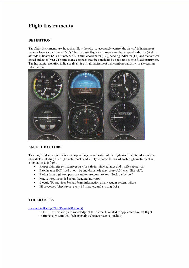
Flight Instruments DEFINITION The flight instruments are those that allow the pilot to accurately control the aircraft in instrument meteorologic al conditions (IMC). The six basic flight instruments are the airspeed indicator (ASI) attitude indicator (AI) altimeter (A!T) turn coordinator (TC) heading indicator ("I) and the #ertical speed indicator ($SI). The magnetic compass may be considered a bac%&up se#enth flight instrument. The hori'ontal situation indicator ("SI) is a flight instrument that combines an "I with na#igation information. SAFETY FACTORS Thorough understanding of normal operating characteristics of the flight instruments adherence to chec%lists including the flight instruments and ability to detect failure of each flight instrument is essential to safe flight. • roper altimeter setting necessary for safe terrain clearance and traffic separation • itot heat in IMC (iced pitot tube and drain hole may cause ASI to act li%e A!T) • lying from high (temperature and*or pressure) to low +loo% out below+ • Magnetic compass is bac%up heading indicator • ,lectric TC pro#ides bac%up ban% information after #acuum system failure • "I precesses (chec%*reset e#ery - minutes and starting IA) TOLERANCES Instrument /ating TS (AA&S&010-&23) II. 4. -. ,xhibit ade5uate %nowledge of the elements related to applicable aircraft flight instrument systems and their operating characteristics to include
-
Upload
mihai-mitrea -
Category
Documents
-
view
230 -
download
0
Transcript of Instrumentele de Zbor Ale Unui Avion
8/13/2019 Instrumentele de Zbor Ale Unui Avion
http://slidepdf.com/reader/full/instrumentele-de-zbor-ale-unui-avion 1/9
Flight Instruments
DEFINITION
The flight instruments are those that allow the pilot to accurately control the aircraft in instrument
meteorological conditions (IMC). The six basic flight instruments are the airspeed indicator (ASI)
attitude indicator (AI) altimeter (A!T) turn coordinator (TC) heading indicator ("I) and the #ertical
speed indicator ($SI). The magnetic compass may be considered a bac%&up se#enth flight instrument.
The hori'ontal situation indicator ("SI) is a flight instrument that combines an "I with na#igation
information.
SAFETY FACTORS
Thorough understanding of normal operating characteristics of the flight instruments adherence to
chec%lists including the flight instruments and ability to detect failure of each flight instrument is
essential to safe flight.
• roper altimeter setting necessary for safe terrain clearance and traffic separation
• itot heat in IMC (iced pitot tube and drain hole may cause ASI to act li%e A!T)
• lying from high (temperature and*or pressure) to low +loo% out below+
• Magnetic compass is bac%up heading indicator
• ,lectric TC pro#ides bac%up ban% information after #acuum system failure
•
"I precesses (chec%*reset e#ery - minutes and starting IA)
TOLERANCES
Instrument /ating TS (AA&S&010-&23)
II. 4. -. ,xhibit ade5uate %nowledge of the elements related to applicable aircraft flight
instrument systems and their operating characteristics to include
8/13/2019 Instrumentele de Zbor Ale Unui Avion
http://slidepdf.com/reader/full/instrumentele-de-zbor-ale-unui-avion 2/9
a. pitot&static
b. altimeter
c. airspeed indicator
d. #ertical speed indicator
e. attitude indicator
f. hori'ontal situation indicator
g. magnetic compassh. turn&and&slip indicator*turn coordinator
i. heading indicator
6. electrical systems
%. #acuum systems
l. electronic flight instrument display
II. C. Instrument Coc%pit Chec%
-. ,xhibit ade5uate %nowledge of the elements related to preflighting instruments
a#ionics and na#igation e5uipment coc%pit chec% by explaining the reasons for the
chec% and how to detect possible defects
7. erform the preflight on instruments a#ionics and na#igation e5uipment coc%pit
chec% by following the chec%list appropriate to the aircraft flown
8. 3etermine that the aircraft is in condition for safe instrument flight including
a. communications e5uipment b. na#igation e5uipment as appropriate to the aircraft flown
c. magnetic compass
d. heading indicator
e. attitude indicator
f. altimeter
g. turn&and&slip indicator
h. #ertical speed indicator
i. airspeed indicator
6. cloc%
%. power source for gyro instruments
l. pitot heat
m. electronic flight instrument displayn. traffic awareness*warning*a#oidance system
o. terrain awareness*warning*alert system
p. MS
5. auto pilot
2. 9ote any discrepancies and determine whether the aircraft is safe for instrument
flight or re5uires maintenance
OBJECTIVES
To de#elop the student:s %nowledge of the flight instruments to meet the AA ractical Test
Standards. To de#elop the student:s understanding of flight instrument operating characteristics the
habit of proper preflight instrument chec%s and ability to detect abnormal or unsafe operation.
PROCEDURES
!ecture*3iscussion;
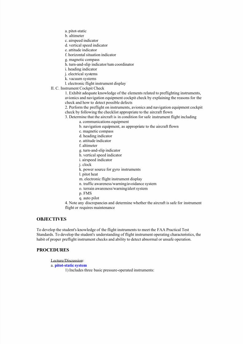
a. pitt!st"ti# s$stem
-) Includes three basic pressure&operated instruments;
8/13/2019 Instrumentele de Zbor Ale Unui Avion
http://slidepdf.com/reader/full/instrumentele-de-zbor-ale-unui-avion 3/9
a) Sensiti#e altimeter
b) Airspeed indicator (ASI)
c) Vertical speed indicator ($SI)
7) Static (ambient) pressure
8) Pitot pressure (impact or ram air pressure)
2) osition error
b. "ltimeter
-) Aneroid barometer
7) rinciple of operation
a) ,#acuated corrugated bron'e aneroid capsules
b) ilot ad6ustable barometric scale #isible in the Kollsman window
8) Altimeter errorsa) reflight chec% for mechanical error ; (75 feet )
b) 9onstandard temperature effects
c) 9onstandard pressure effects (+flying from high to low loo% out below<+)
2) Encoding altimeter
a) Mode C transponder
b) %&' (eet
) Absolute altimeter (radar or radio altimeter)
c. "irspee) in)i#"tr *ASI+
8/13/2019 Instrumentele de Zbor Ale Unui Avion
http://slidepdf.com/reader/full/instrumentele-de-zbor-ale-unui-avion 4/9
-) ASI is a differential pressure guage that measures dynamic pressure
7) Indicated airspeed (IAS
8) !alibrated airspeed (!AS
2) E"ui#alent air speed (EAS
) $rue airspeed ($AS (TAS = CAS standard atmosphere at sea le#el)
>) %ach number (TAS;speed of sound)
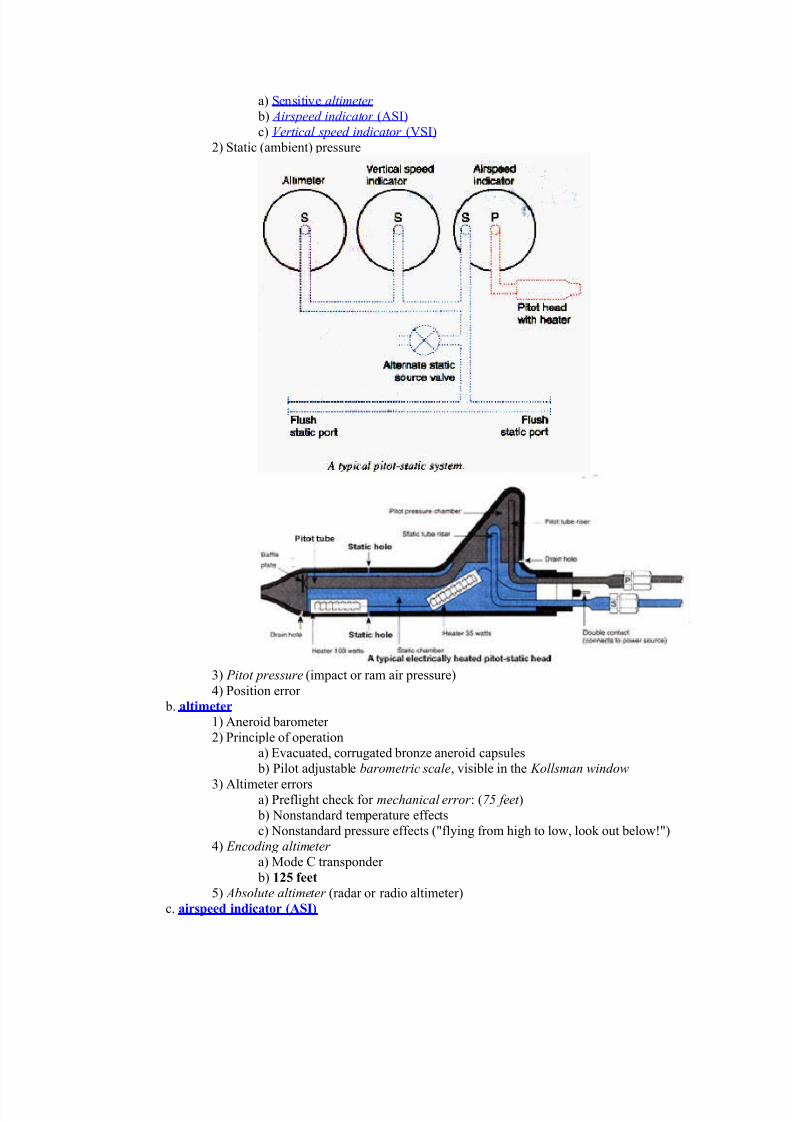
?) Airspeed color codes; @hite arc; flap&operating range (from flaps&down stall speed to maximum
airspeed with flaps down)
reen arc; 9ormal operating range (from flaps&up stall speed to maximum
airspeed in rough air)
4lue radial line; 4est single&engine rate of climb speed
Bellow arc; Structural warning area (from maximum rough air speed to
ne#er&exceed speed)
/ed radial line; 9e#er&exceed speed
d. ,erti#"l spee) in)i#"tr *VSI+ (#ertical #elocity indicator $$I rate&of&climb indicator)
-) /ate&of&pressure&change instrument
7) Static pressure and calibrated orifice
8) $SI lags behind actual pressure change but more sensiti#e than alitimeter
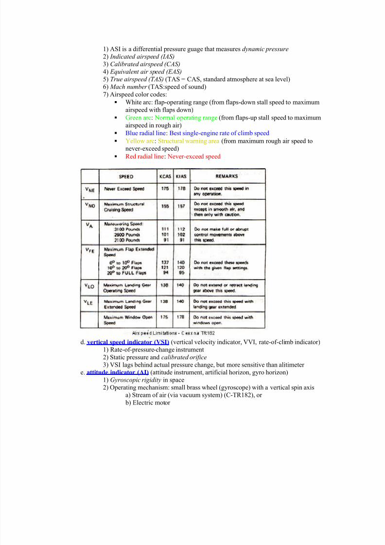
e. "ttitu)e in)i#"tr *AI+ (attitude instrument artificial hori'on gyro hori'on)
-) &yroscopic rigidity in space7) perating mechanism; small brass wheel (gyroscope) with a #ertical spin axis
a) Stream of air (#ia #acuum system) (C&T/-07) or
b) ,lectric motor
8/13/2019 Instrumentele de Zbor Ale Unui Avion
http://slidepdf.com/reader/full/instrumentele-de-zbor-ale-unui-avion 5/9
8) 'orion dis) fixed to gimbals remains in same plane as gyro
a) itch mar%s
b) 4an% index
2) Symbolic aicraft mounted on instrument case o#er hori'on dis% ) Erection mechanism (7 to minutes)
>) lder gyros caging mechanism
?) ,rrors
a) Slight nose up or down during rapid acceleration or deceleration
respecti#ely
b) ossible small ban% and pitch errors after -01 degree turn
c) ,rrors are small and correct themsel#es within a minute or so in S!
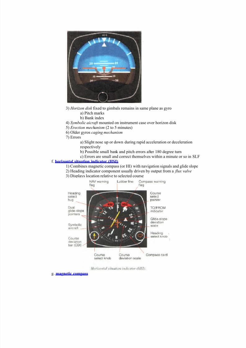
f. hri-nt"l situ"tin in)i#"tr *.SI+
-) Combines magnetic compass (or "I) with na#igation signals and glide slope
7) "eading indicator component usually dri#en by output from a flu* #al#e
8) 3isplays location relati#e to selected course
g. m"gneti# #mp"ss
8/13/2019 Instrumentele de Zbor Ale Unui Avion
http://slidepdf.com/reader/full/instrumentele-de-zbor-ale-unui-avion 6/9
-) perating principle & free magnets align with the earth:s lines of flux
7) /e5uired by -2 C/ part D- for both $/ and I/ flight
8) Components
a) Two small magnets
b) Metal float
c) Clear fluid
d) raduated scale the carde) !ubber line reference
f) Eewel&and&pi#ot type mounting
g) Compensator assembly
2) Compass errors
a) Variation
MC = TC F @est $ariation
MC = TC & ,ast $ariation
b) +e#iation
i) Caused by local magnetic fields within the aircraft
ii) /ecorded on compass correction card
c) !ompass course (!!
True course (TC) corrected for #ariation ($) and de#iation (3)
TC /0! V 1 2C /0! D 1 CCd) +ip errors
i) 9ortherly turning error
NOSE (+9orth pposite South ,xaggerates+)
ii) Acceleration error
ANDS (Accelerate 9orth 3ecelerate South)
e) scillation error
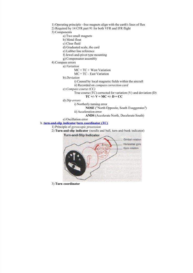
h. turn!"n)!slip in)i#"tr0turn #r)in"tr *TC+
-) rinciple of gyroscopic precession
7) Turn!"n)!slip in)i#"tr (needle and ball turn&and&ban% indicator)
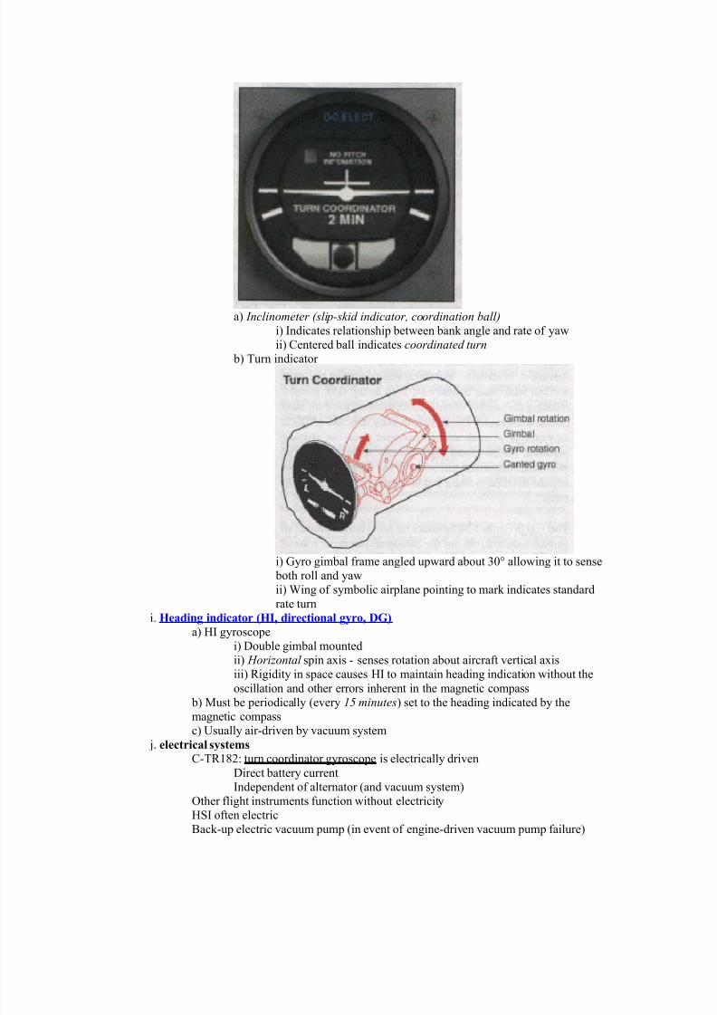
8) Turn #r)in"tr
8/13/2019 Instrumentele de Zbor Ale Unui Avion
http://slidepdf.com/reader/full/instrumentele-de-zbor-ale-unui-avion 7/9
a) Inclinometer (slip,s)id indicator- coordination ball
i) Indicates relationship between ban% angle and rate of yaw
ii) Centered ball indicates coordinated turn
b) Turn indicator
i) yro gimbal frame angled upward about 81G allowing it to sense
both roll and yaw
ii) @ing of symbolic airplane pointing to mar% indicates standard
rate turn
i. .e")ing in)i#"tr *.I3 )ire#tin"l g$r3 D4+
a) "I gyroscope
i) 3ouble gimbal mounted
ii) 'oriontal spin axis & senses rotation about aircraft #ertical axis
iii) /igidity in space causes "I to maintain heading indication without the
oscillation and other errors inherent in the magnetic compass
b) Must be periodically (e#ery .5 minutes) set to the heading indicated by the
magnetic compass
c) Hsually air&dri#en by #acuum system
6. ele#tri#"l s$stems
C&T/-07; turn coordinator gyroscope is electrically dri#en
3irect battery current
Independent of alternator (and #acuum system)
ther flight instruments function without electricity
"SI often electric
4ac%&up electric #acuum pump (in e#ent of engine&dri#en #acuum pump failure)
8/13/2019 Instrumentele de Zbor Ale Unui Avion
http://slidepdf.com/reader/full/instrumentele-de-zbor-ale-unui-avion 8/9
%. ,"#uum s$stems
AI and "I gyros dri#en by engine&operated #acuum pump
Monitor suction gauge (2. & .2 in"g)
Additional bac%&up electric #acuum pump recommended
Cessna T/-07 #acuum system
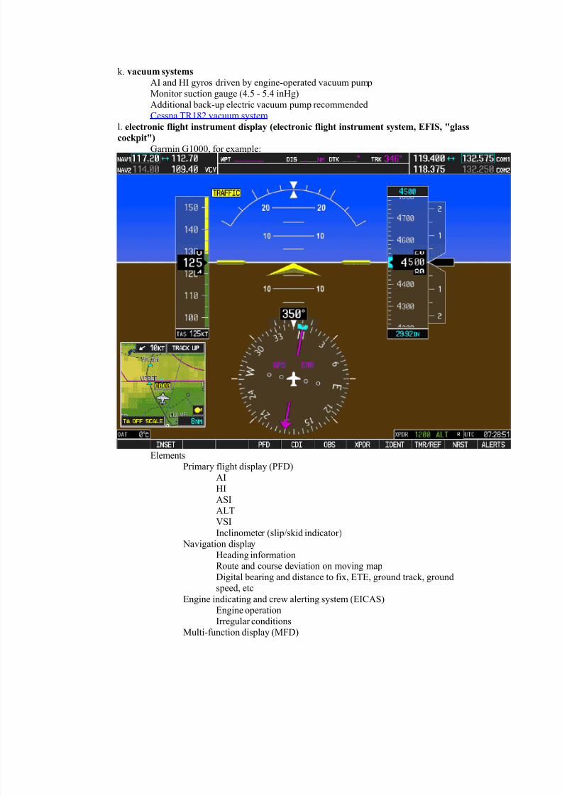
l. ele#trni# (light instrument )ispl"$ *ele#trni# (light instrument s$stem3 EFIS3 5gl"ss
##6pit5+armin -111 for example;
,lements
rimary flight display (3)
AI
"I
ASI
A!T
$SI
Inclinometer (slip*s%id indicator)
9a#igation display
"eading information/oute and course de#iation on mo#ing map
3igital bearing and distance to fix ,T, ground trac% ground
speed etc
,ngine indicating and crew alerting system (,ICAS)
,ngine operation
Irregular conditions
Multi&function display (M3)
8/13/2019 Instrumentele de Zbor Ale Unui Avion
http://slidepdf.com/reader/full/instrumentele-de-zbor-ale-unui-avion 9/9
Status of aircraft systems
ther optional information (weather TCAS info)
perate according to manufacturers recommendations and " supplements
reflight instrument chec%
a. #mmuni#"tins e7uipment
b. n",ig"tin e7uipment3 "s "pprpri"te t the "ir#r"(t (l8nc. m"gneti# #mp"ss
d. he")ing in)i#"tr
e. "ttitu)e in)i#"tr
f. "ltimeter
g. turn!"n)!slip in)i#"tr
h. ,erti#"l spee) in)i#"tr
i. "irspee) in)i#"tr
6. #l#6
%. p8er sur#e (r g$r instruments
TC & electric*ammeter*low #oltage light
AI and "I & #acuum*suction guage*low&#acuum warning light*bac%up electric
#acuum
l. pitt he"t (and prop deice)Ammeter indication
"eat
m. ele#trni# (light instrument )ispl"$
Chec% according to manufacturers recommendations in " supplements
n. tr"((i# "8"reness08"rning0",i)"n#e s$stem
Chec% according to manufacturers recommendations in " supplements
o. terr"in "8"reness08"rning0"lert s$stem
Chec% according to manufacturers recommendations in " supplements
p. F2S
Chec% according to manufacturers recommendations in " supplements
5. "ut pilt
Chec% according to manufacturers recommendations in " supplementsor example C&T/-07 chec%list for S&T,C >1
CO22ON ERRORS
• ailure to study " for details of operation of instruments in a specific aircraft
• ailure to complete preflight instument chec%
• ailure to detect instrument defects
Re(eren#es
-2 C/ parts >- and D-
Instrument light Maneu#ers 2th ,dition leim 7112
Instrument lying "andboo% AA&"&0108&- -DDDInstrument /ating TS AA&S&010-&23 April 7112
" for aircraft flown (e.g. C&T/-07)