Horizontal multistage centrifugal pumps Horizontale ... · 2 Pompa centrifugală orizontală...
16
Pompe centrifugale orizontale multietajate Horizontale, mehrstufige Kreiselpumpen Horizontal multistage centrifugal pumps BM Mai mult decât pompe 08 0036.0130_BM_OST_2_EBZ_2005/3 D_F_E 15.05.12 10:57 Seite 1
Transcript of Horizontal multistage centrifugal pumps Horizontale ... · 2 Pompa centrifugală orizontală...
Pompe centrifugale orizontale multietajateHorizontale, mehrstufige KreiselpumpenHorizontal multistage centrifugal pumps
BM
Mai mult decât pompe
08 0036.0130_BM_OST_2_EBZ_2005/3 D_F_E 15.05.12 10:57 Seite 1
2
Pompa centrifugală orizontală
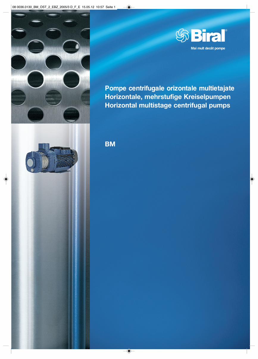
Pompele din seria BM sunt în mod normal pompe centrifugale orizontalemultietajate. Pompa şi motorul sunt legate direct între ele. Pompele au o duză de aspiraţie axială şi una de refulare radială, fiind echipatecu o placă de bază.Pompele BM sunt produse standardadaptate special cerinţelor clienţilor,putând fi utilizate într-o multitudine de aplicaţii. Aceste pompe sunt disponibilela dimensiuni de construcţie şi trepte diferite, pentru a acoperi un gamă largăde debite şi de presiuni de pompare. Pompele BM constau din două componente principale: mecanismul de acţionare şi unitatea pompei.Mecanismul de acţionare este un motorîn conformitate cu normele EN în vigoare.Unitatea pompei constă din componentehidraulice cu randament optimizat şi carcasa pompei cu duze de aspiraţie şi de refulare.
Avantaje– construcţie compactă– fiabilitate mare– uşor de întreţinut şi de reparat– interval de putere mai mare– silenţioase
AplicaţiiPompele BM acoperă un interval larg de aplicaţii, de la instalaţiile mici –din domeniul casnic, până la instalaţiileindustriale mari. Astfel, pompele sunt adecvate pentru utilizarea în numeroaseinstalaţii cu pompe, care impun cerinţefoarte speciale cu privire la puterea şi materialele pompelor. Unele dintre cele mai importante aplicaţii sunt următoarele: – Sisteme de răcire– Creşterea presiunii– Instalaţii de spălare– Irigaţii şi fântâni– Prepararea apei
Horizontale Kreiselpumpe
Die Pumpen der Baureihe BM sind normalsaugende, horizontale, mehrstufige Kreiselpumpen. Pumpe und Motor sind direkt miteinander verbunden. Die Pumpen haben einen axialenSaugstutzen und einen radialenDruckstutzen und sind mit einerGrundplatte ausgerüstet. Die BM-Pumpen sind speziell aufKundenanforderungen zugeschnitteneStandardprodukte, die in einer Vielzahlvon Anwendungen eingesetzt werdenkönnen. Diese Pumpen sind in unterschiedlichen Baugrössen und mitverschiedenen Stufenzahlen lieferbar, um einen grossen Förderstrom- und Förderdruckbereich abdecken zu können. Die BM-Pumpen bestehen aus zweiHauptkomponenten; dem Antrieb und der Pumpeneinheit.Beim Antrieb handelt es sich um einen,den geltenden EN-Normen ent-sprechenden Motor. Die Pumpeneinheitbesteht aus den wirkungsgradoptimiertenHydraulikkomponenten und demPumpengehäuse mit dem Saug- und Druckstutzen.
Vorteile– kompakte Bauweise– hohe Zuverlässigkeit– wartungs- und reparaturfreundlich– grosser Leistungsbereich– geräuscharm
AnwendungenDie BM-Pumpen decken einen weitenAnwendungsbereich ab – angefangenvon kleinen Installationen im häuslichenBereich bis hin zu grossen Industrie-anlagen. Die Pumpen sind somit für den Einsatz in vielfältigen Pumpen-installationen geeignet, die wiederumganz spezielle Anforderungen an dieLeistung und die Werkstoffe der Pumpestellen. Einige der wichtigstenAnwendungen sind im Folgenden aufgeführt: – Kühlsysteme– Druckerhöhung– Waschanlagen– Bewässerung und Brunnen– Wasseraufbereitung
Horizontal centrifugal pump
The pumps of the BM-range are non-selfpriming, horizontal, multistage,end-suction centrifugal pumps. The pumps are of the close-coupledtype. The pumps have a radial suctionand an axial discharge branch and are fitted to a low-profile base plate.The BM pumps are unique products that have been developed in order to fulfil a wide variety of customerdemands.Those pumps are available in varioussizes and numbers of stages in order to cover a wide flow and pressure range.The BM pumps consist of two main components: the motor and the pumpunit.The drive is a motor designed to ENstandards. The pump unit incorporatesoptimised hydraulics for high efficiencyand the pump housing with inlet anddischarge branch.
Advantages– Compact design– High reliability– Service-friendly– Wide performance range– Low noise level
ApplicationsThe BM pumps are designed to cover a wide variety of applications, rangingfrom small domestic installations to large industrial systems. The pumps are therefore suitable for a wide diversity of pumping systemswhere the performance and material ofthe pump must meet specific demands.Some of the most typical applications are mentioned below:– washing and cleaning system– water treatment– cooling systems– pressure boosting– irrigation and fountains
08 0036.0130_BM_OST_2_EBZ_2005/3 D_F_E 15.05.12 10:57 Seite 2
BM
Caracteristici produs 4ProdukteigenschaftenFeatures and benefits
Condiţii de funcţionare Fluide 5Betriebsbedingungen FördermedienOperating conditions Pumped liquids
Vâscozitate 5ViskositätViscosity
Temperaturi 5TemperaturenTemperature
Motor 6Motor Motor
Funcţionarea convertizorului de frecvenţă 7FrequenzumrichterbetriebFrequency converter operation
Etanşare mecanică 7GleitringdichtungShaft seal
Montarea pompei 8Aufstellung der PumpeInstallation of pump
Codul modelului 8TypenschlüsselType designation
Presiunea de admisie minimă, NPSH 9Mindestzulaufdruck, NPSHMinimum inlet pressure, NPSH
Materiale 10WerkstoffeMaterials
Curbe colective 11SammelkurveJoint charachteristics
Caracteristici 12-14KennlinienPerformance curves
Dimensiuni 12-14MassbilderDimensions
Componente 15BauteileComponents
CuprinsInhaltsübersichtTable of contents
3
08 0036.0130_BM_OST_2_EBZ_2005/3 D_F_E 15.05.12 10:57 Seite 3
Caracteristici produs
Construcţie compactăPompa şi motorul formează o unitate.Pompa este montată pe o placă de bază mică; ideal în instalaţiile cu spaţiu redus.
Fiabilitate mare– Garniturile inelare glisante, care
respectă cele mai recente tehnologii şi sunt echipate cu cele mai moderne combinaţii de materiale (carbură de siliciu SiC-G),oferă următoarele avantaje:
– rezistenţă mare la uzură şi durată de viaţă lungă
– caracteristici îmbunătăţite pentru funcţionarea pe uscat şi tendinţă mai redusă de lipire
– mai puţin sensibile la impurităţi
Instalare şi punere în funcţiune simple– Manual de montaj şi utilizare
cuprinzător, în mai multe limbi, furnizat cu produsul
– Pompele trifazate au un indicator al directiei de rotatie, pentru controlul uşor al racordării electrice a motorului.
Uşor de întreţinut şi de reparat– Construcţie uşor de întreţinut
şi de reparat– Nu sunt necesare unelte speciale.– Piesele de schimb se pot procura rapid– Toate componentele se pot livra
ca seturi de piese de schimb, ca piese de schimb sau în unităţi de ambalare mai mari.
Interval de putere mai marePompele se pot utiliza într-o multitudinede aplicaţii, ca de exemplu:– Spălare şi curăţare– Prepararea apei– Controlul temperaturii– Creşterea presiunii
SilenţioasePompele BM facilitează o funcţionaredeosebit de silenţioasă.
Sistem hidraulic de mare putereEficienţa pompelor poate fi crescută la maximum prin optimizarea sistemuluihidraulic şi utilizarea celor mai modernetehnologii de fabricare.
Produkteigenschaften
Kompakte BauweisePumpe und Motor bilden eine Einheit.Die Pumpe ist auf einer kleinenGrundplatte montiert; ideal in Anlagenmit beengten Platzverhältnissen.
Hohe Zuverlässigkeit– Gleitringdichtungen, die dem neusten
Stand der Technik entsprechen und mit modernsten Werkstoffpaarungen (Siliziumkarbid SiC-G) ausgestattet sind, bieten folgende Vorteile:
– hohe Verschleissfestigkeit und lange Lebensdauer
– verbesserte Trockenlaufeigenschaften und geringere Neigung zum Verkleben
– wenig anfällig gegenüber Verunreinigungen
Einfache Installation und Inbetriebnahme– Ausführliche mehrsprachige Montage-
und Bedienungsanleitung beim Produkt
– Dreiphasige Pumpen verfügen über eine Drehrichtungssanzeige des Motor, zur leichten Kontrolle des elektrischen Anschlusses des Motors.
Wartungs- und reparaturfreundlich– Wartungs- und reparaturfreundliche
Bauweise– Kein Sonderwerkzeug erforderlich.– Ersatzteile sind schnell verfügbar– Alle Bauteile sind als Ersatzteilsätze,
Einzelteile oder in grösseren Verpackungseinheiten lieferbar
Grosser LeistungsbereichDie Pumpen können in einer Vielzahl von Anwendungen eingesetzt werden,wie zum Beispiel:– Waschen und Reinigen– Wasseraufbereitung– Kühlen und Temperieren– Druckerhöhung
GeräuscharmDie BM-Pumpen ermöglichen einen äusserst geräuscharmen Betrieb.
HochleistungshydraulikDie Effizienz der Pumpen konnte durch Optimierung der Hydraulik und den Einsatz modernsterFertigungstechnologien auf ein Maximum gesteigert werden.
Features and benefits
Compact designPump and motor are integrated in a compact and userfriendly design.The pump is fitted to a low-profile baseplate, making it ideal for installation in systems where compactness is important.
High reliability– New state-of-the-art shaft seal design
and materials offering these benefits:– high wear resistance
and long operating life– improved sticking
and dry-running capabilities– The pumps are less sensitive
to impurities in the pumped liquid type
Easy installation and commissioning– Detailed installation and operating
instructions are deliveredwith the product
– An installation indicator is fitted on three-phase pumps, for the easy controle of the direction of rotation of the motor.
Service-friendly– Service-friendly construction– No special service tools required– Spare parts in stock for quick delivery– Spare parts are available as kits,
single parts or bulks– Service instructions and video
make it simple to– disassemble and assemble the pump
Wide performance rangeThe pumps can be used in a wide rangeof applications like e.g.:– washing and cleaning– water treatment– temperature control– pressure boosting
Low noise levelThe BM pumps offer very silent operation.
High-performance hydraulicsPump efficiency is maximised by the optimised hydraulics and carefully crafted production technology.
4
08 0036.0130_BM_OST_2_EBZ_2005/3 D_F_E 15.05.12 10:57 Seite 4
5
Condiţii de funcţionare
FluideFluide cu densitate redusă, neexplozive,fără componente solide sau cu fibre lungi.Fluidul nu trebuie să atace chimic saumecanic materialele pompei. Pentru pomparea fluidelor ale căror densitate şi/sau vâscozitate sunt mai mari decât ale apei, dacă este cazul seutilizează motoare cu o putere mai mare. Dacă o pompă este adecvată pentru unanumit fluid, depinde de mai mulţi factori. Cei mai importanţi factori sunt conţinutulde clor, valoarea pH-ului, temperatura şiconţinutul de substanţe chimice sau ulei.Trebuie să aveţi în vedere că fluidele agresive (de ex. apa de mare sau uniiacizi) pot ataca sau dizolva stratul protector de oxid de pe oţelul inoxidabil şi astfel poate apărea coroziunea.
VâscozitateaPrin pomparea lichidelor cu o densitatesau o vâscozitate cinematică diferită de cea a apei, se produce o cădere mare de presiune, precum şi o reducere a puterii hidraulice. Consecinţa este un consum mai mare de energie. Aşadar, la temperatura fluidelor sub 0 °C, din cauza vâscozităţii mari, de ex. din cauză că amestecul apă-glicoleste utilizat ca antigel, se va selecta un motor cu puterea mai mare.
Temperatura ambiantă max. +55 °C
Presiunea de funcţionare maximă admisăşi temperatura fluidului maximă admisă–20 °C până la +40 °C: 10 bar+41 °C până la +90 °C: 6 bar
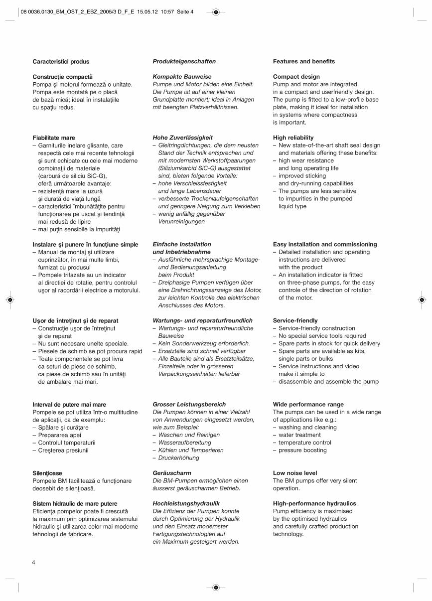
Temperatura ambiantă şi înălţimea de amplasareÎn cazul valorii temperaturii ambiante mai mare de +55 °C sau daca motoruleste amplasat la o altitudine mai mare de 1000 m, trebuie utilizat un motor maimare (vezi fig. 1).
Betriebsbedingungen
FördermedienDünnflüssige, nicht-explosive Medienohne abrasive oder langfaserigeBestandteile. Das Fördermedium darf die Pumpenwerkstoffe weder chemischnoch mechanisch angreifen. Zur Förderung von Medien, deren Dichteund/oder Viskosität grösser sind als dievon Wasser, sind ggf. Motoren mit einerhöheren Leistung einzusetzen. Ob eine Pumpe zur Förderung einesbestimmten Mediums geeignet ist, hängt von mehreren Faktoren ab. Die wichtigsten Faktoren sind der Chlorid-gehalt, der pH-Wert, die Temperatur und der Gehalt an Chemikalien oder Öl.Es ist zu beachten, dass agressive Medien(z. B. Seewasser oder einige Säuren) dieschützende Oxidschicht von Edelstahlangreifen oder abbauen können, sodass Korrosion entstehen kann.
ViskositätDurch die Förderung von Flüssigkeitenmit einer von Wasser abweichendenDichte oder kinematischen Viskositätkommt es zu einem grösseren Druck-abfall sowie zu einem Absinken derhydraulischen Leistung. Die Folge ist einerhöhter Leistungsbedarf. So ist beiMedientemperaturen unter 0 °C wegender höheren Viskosität, z. B. weil demWasser Glykol als Frostschutz hinzu-gefügt wird, ggf. ein Motor mit höhererLeistung zu wählen.
Max. zulässige Umgebungstemperatur +55 °C
Maximal zulässiger Betriebsdruck undmaximal zulässige Medientemperatur–20 °C bis +40 °C: 10 bar+41 °C bis +90 °C: 6 bar
Umgebungstemperatur und Aufstellungshöhe Bei höheren Werten als Umgebungs-temperatur +55 °C oder Aufstellungsort1000 m muss ein grösserer Motor eingesetzt werden (siehe Abb. 1).
20 25 30 35 40 45 50 55 60 65 70 75 80
50
60
70
80
90
100
[%]P2
t [°C ]
1000 2250 3500 4750 m
BM
Operating conditions
Pumped liquidsThin, non-explosive liquids, not containingsolid particles or fibres. The liquid mustnot chemically attack the pump materi-als. When pumping liquids with a densityand/or viscosity higher than those of water, oversized motors must be used,if required. Whether a pump is suitablefor a particular liquid depends on a number of factors of which the mostimportant are the chloride content, pH value, temperature and content ofchemicals and oils. Please note thataggressive liquids (for instance seawaterand some acids) may attack or dissolvethe protective oxide film of the stainlesssteel and thus cause corrosion.
ViscosityThe pumping of liquids with densities or kinematic viscosities higher than thoseof water will cause a considerable pressure drop, a drop in the hydraulicperformance and a rise in the power consumption. For instance at liquid temperatures below 0 °C , higher motoroutputs may be needed due to increasedviscosity if glycol has been added to the water. In such situations, the pumpshould be fitted with a larger motor.
Ambient temperatureMax. +55 °C
Maximum ambient temperature in relation to liquid temperature–20 °C bis +40 °C: 10 bar+41 °C bis +90 °C: 6 bar
Ambient temperature and altitudeabove sea levelIf the ambient temperature exceeds +55 °C, or if the motor is on a locationhigher than 1000 m a.s.l., it may benecessary to use an oversize motor with higher rated output (see fig. 1).
Fig./Abb. 1Legătura dintre puterea de evacuare a motorului (P2), temperatura ambiantă şi înălţimea de ampasare.
Zusammenhang zwischen der Motor-ausgangsleistung (P2) und derUmgebungstemperatur-Aufstellungshöhe.
Relationship between motor output (P2) and ambient temperature or motor output (P2) and altitude.
08 0036.0130_BM_OST_2_EBZ_2005/3 D_F_E 15.05.12 10:57 Seite 5
6
Motor 3× 220-240/380-415 V, 50 Hz
MărimeFrame P2 I 1/1 I start
Tip [kW] [A] [A]
71 0,65 2,8-3,1/1,6-1,8 16,2-19,2/9,3-11,280 1,20 4,6-5,2/2,6-3,0 26,7-32,8/15,1-18,990 2,20 7,2-7,7/4,1-4,4 50,4-58,5/28,7-33,4
100 3,20 11,0-11,8/6,4-6,0 94,4-96,8/54,0-56,3100 4,00 13,2-14,0/7,8-8,2 119,0-125,4/69,7-74,1132 5,80 19,0-24,4/11,0-11,8 181,6-184,3/105,0-106,7132 7,40 25,5-27,0/14,8-15,6 245,7-252,5/142,0-146,5
Motor 1× 220-240 V, 50 Hz
MărimeFrame P2 I 1/1 I start
Tip [kW] [A] [A]
71 0,30 1,8-2,4 6,1-8,271 0,50 3,1-2,8 14,8-16,480 0,67 4,0-4,4 15,6-17,280 0,90 5,0-5,4 21,5-23,290 1,30 8,0-8,4 27,2-28,690 1,70 10,0-11,0 37,0-40,7
MotorPompele BM sunt acţionate de un motorcomplet încapsulat, răcit cu un ventilator,cu 2 poli. Dimensiunile principale corespund cu EN 50437. Intervalul de toleranţă electrică în conformitate cu EN 60034.Pompele BM până la 1,3 kW inclusiv sunt echipate standard cu motoare monofazate. De la 3,2 kW până la 7,5 kW,acestea sunt acţionate exclusiv demotoare trifazate.
Turaţia nominală: 2900 1/minClasa de protecţie: IP 55Clasa de izolare: FTensiuni 1× 220-240 V, 50 Hzstandard: 3× 380-415 V, 50 Hz
Clasa de eficienţă: IE2Motoare trifazate>0,75 kWIE1Motoare monofazate
MotorDie BM-Pumpen werden von einem vollständig gekapselten, lüftergekühlten,2-poligen Motor angetrieben. Die Hauptabmessungen entsprechen der EN 50437. Elektrischer Toleranz-bereich nach EN 60034.BM-Pumpen bis einschliesslich 1,3 kWsind standardmässig mit einphasigenMotoren ausgerüstet. Ab 3,2 kW bis 7,5 kW werden sie ausschliesslich vonDrehstrommotoren angetrieben.
Nenndrehzahl: 2900 1/minSchutzart: IP 55Isolationsklasse: FStandard- 1×220-240 V, 50 Hzspannungen: 3×380-415 V, 50 Hz
Effizienzklasse: IE2dreiphasige Motoren>0,75 kWIE1einphasige Motoren
MotorBM pumps are fitted with totally enclosed, fan-cooled, 2-pole motors with principal dimensions to EN 50347.Electrical tolerances comply with EN 60034.BM pumps up to and including 1,3 kWare fitted with single-phase motors as standard. From 3,3 to 7,5 kW the pumps aresolely fitted with three-phase motors.
Nominal speed: 2900 rpmEnclosure class: IP 55Insulation class: FSupply voltages: 1×220-240 V, 50 Hz
3×380-415 V, 50 Hz
Efficiency class: IE2three-phase motors>0,75 kWIE1single-phase motors
Protecţia motoruluiMotoarele monofazate dispun de o protecţie integrată, în funcţie de curentşi temperatură, conform IEC 60034-11 şide aceea nu necesită nicio altă protecţie.Protecţia motorului corespunde cu clasade protecţie TP 211. Protecţia motorului se resetează automatdupă declanşare. Motoarele trifazate cu o putere de până la 3 kW trebuie să se conecteze la un întrerupător de circuit extern, care să poată fi resetat manual. Setaţi întrerupătorul de circuit conformcurentului nominal al motorului (I1/1). Motoarele cu o putere de peste 3 kW au un termistor (PTC) integrat.Termistorul este construit conform DIN 44082. Protecţia motorului corespunde cu clasa de protecţie TP 211.
MotorschutzDie einphasigen Motoren verfügen übereinen integrierten, strom- und temperatur-abhängigen Motorschutz nach IEC60034-11 und benötigen deshalb keinenweiteren Motorschutz. Der Motorschutzentspricht dem Schutzgrad TP 211. Der Motorschutz wird nach demAuslösen automatisch zurückgesetzt. Drehstrommotoren mit einer Leistung bis 3 kW sind an einen externenMotorschutzschalter anzuschliessen, der manuell zurückgesetzt werden kann.Den Motorschutzschalter entsprechenddem Motoren-Nennstrom (I1/1) einstellen. Motoren mit einer Leistung über 3 kWhaben einen eingebauten Thermistor(PTC). Der Thermistor ist gemäss DIN 44082 ausgeführt. Der Motorschutzentspricht dem Schutzgrad TP 211.
Motor protectionSingle-phase motors have built-in current- and temperature-dependentmotor protection in accordance with IEC 60034-11 and require no furthermotor protection. The motor protection is of the TP 211 type, which reacts to bothslow- and quick-rising temperatures. The motor protection is automaticallyreset.Three-phase motors up to 3 kW must beconnected to a motor-protective circuitbreaker which can be manually reset. Set the motor-protective circuit breakeraccording to the rated current of themotor (I1/1).Motors with power ratings of 3 kW and up have built-in thermistors (PTC).The thermistors are designed accordingto DIN 44082. The motor protection is of the TP 211 type.
08 0036.0130_BM_OST_2_EBZ_2005/3 D_F_E 15.05.12 10:57 Seite 6
7
Funcţionarea convertizorului de frecvenţăToate motoarele trifazate pot fi conectatela un convertizor de frecvenţă. În funcţie de tipul convertizorului de frecvenţă, se pot produce zgomoteamplificate ale motorului. Suplimentar, la utilizarea unui convertizorde frecvenţă extern, motorul poate fisupus unor vârfuri de tensiune negative.Motoarele cu dimensiunea de construcţie71 şi 80 nu au nicio izolare a fazelor şi astfel trebuie protejate împotriva vârfurilor de tensiune mai mari de 650 V(valoarea vârfului), care pot apărea întrebornele de alimentare. Dezavantajele de mai sus, atât zgomotele,cât şi vârfurile de tensiune negative, se pot elimina prin montarea unui filtru LCîntre convertizorul de frecvenţă şi motor Alte informaţii se obţin de la producătorulconvertizorului de frecvenţă.Debitul minim = 12,5 % (din debitul nominal la temperatura fluidului de 90 °C).
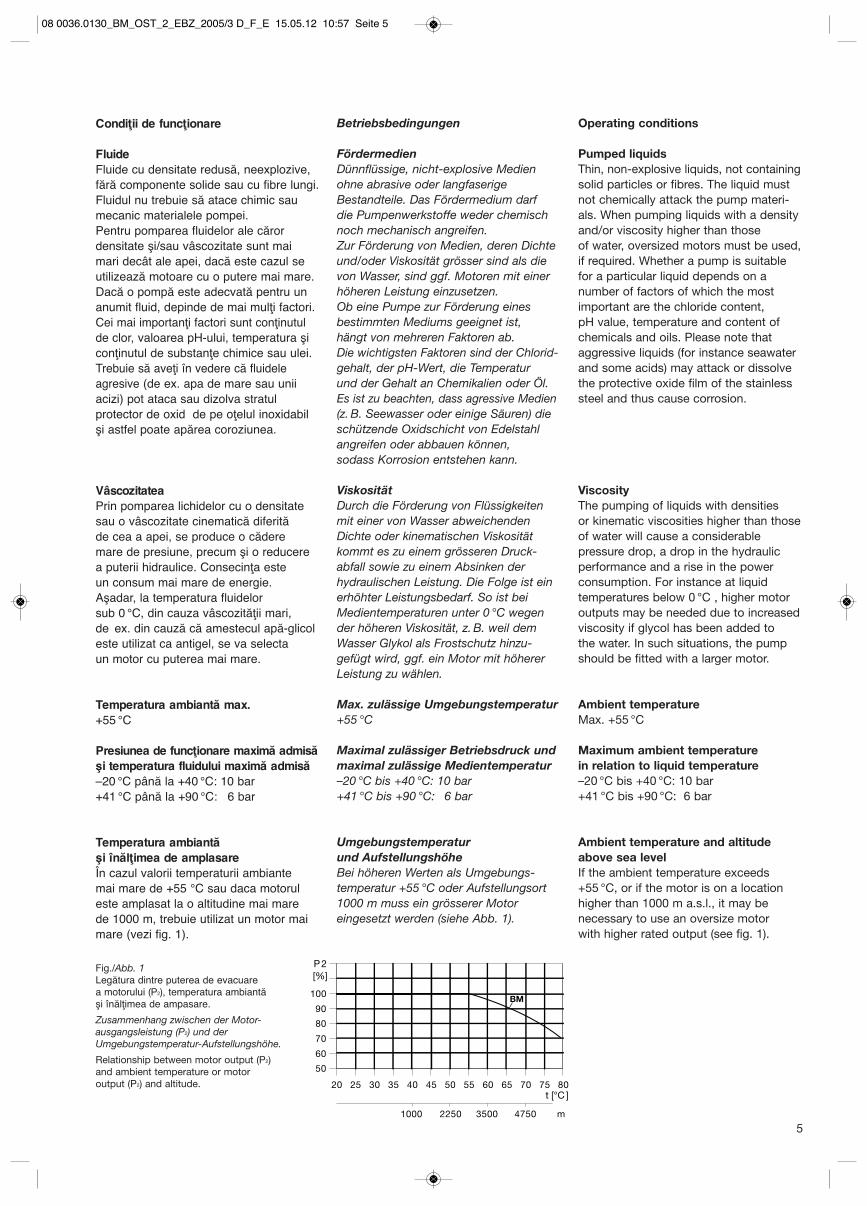
Etanşarea mecanicăPentru pompele BM se utilizează etanşări de tipul celor inelare. Etanşareamecanică are o camă fixă, astfel încât să se asigure o rotire sigură a tuturorcomponentelor – chiar şi în condiţii de funcţionare – extreme. Datorită configuraţiei speciale a etanşăriimecanice şi a îmbinării elaborate a acesteia cu celelalte componente ale pompei, caracteristicile pentru funcţionarea pe uscat s-au îmbunătăţitsemnificativ în comparaţie cu alte tipuride pompe. În plus, pericolul lipirii supra-feţelor glisante s-a redus vizibil (figura 2).
FrequenzumrichterbetriebAlle Drehstrommotoren können an einenFrequenzumrichter angeschlossen werden. Je nach Frequenzumrichtertypkönnen jedoch erhöhte Motorgeräuscheauftreten. Ausserdem kann der Motor bei Einsatz eines externen Frequenz-umrichters schädlichen Spannungs-spitzen ausgesetzt werden. Motoren derBaugrösse 71 und 80 haben standard-mässig keine Phasenisolierung und sinddeshalb vor schädlichen Spannungs-spit-zen grösser als 650 V (Spitzenwert), die zwischen den Versorgungsklemmenauftreten können, zu schützen. Die oben genannten Beeinträchtigungen,d. h. sowohl Geräusche als auch schädliche Spannungsspitzen, lassensich durch den Einbau eines LC-Filterszwischen dem Frequenzumrichter und dem Motor beseitigen. Weitere Informationen erhalten Sie vom Hersteller des Frequenzumrichters.Mindestförderstrom = 12,5% (vom Nenn-förderstrom bei Medientemperatur 90 °C).
GleitringdichtungFür die BM-Pumpen werden Gleitring-dichtungen in O-Ring-Ausführung verwendet. Die Gleitringdichtung hateinen festen Mitnehmer, sodass einesichere Rotation aller Bauteile – auchunter extremen Betriebsbedingungen –gewährleistet ist. Dank der besonderenGestaltung der Gleitringdichtung undihrer durchdachten Anbindung an dierestlichen Pumpenbauteile wurden dieTrockenlaufeigenschaften im Vergleich zu anderen Pumpentypen erheblich verbessert. Zudem wurde auch die Gefahrdes Zusammenklebens der Gleitflächenspürbar reduziert (Abbildung 2).
Frequency converter operationAll three-phase motors can be connectedto a frequency converter. Depending onthe frequency converter type, this maycause increased acoustic noise from the motor. Furthermore, it may cause the motor to be exposed to detrimentalvoltage peaks.As standard frame size 71- and 80-basedmotors have no phase insulation andmust therefore be protected against voltage peaks higher than 650 V (peak value) between the supply terminals.The above disturbances, i.e. both increased acoustic noise and detrimentalvoltage peaks, can be eliminated by fitting an LC filter between the frequency converter and the motor.For further information, please contactthe frequency supplier.Minimum flow of 12,5% of the nominalflow at liquid temperature of 90 °C.
Shaft sealThe shaft seal for the BM pumps is of the O-ring type. The shaft seal has a fixed seal driver which ensures a reliablerotation of all parts – even under the mostextreme operating conditions. Due to the special design of the shaft sealand the interfaces to the rest of the pumpconstruction, the dry-running capabilitiesare improved significantly compared tomost other similar shaft seals and pumptypes. Furthermore, improvements havebeen made to reduce the risk and effectof sticking (see fig. 2).
Floor
Up
16
10
6
2
-30* -20* 0* +40 +90 +120
t [°C]
p [bar]
AVBE
AVBE
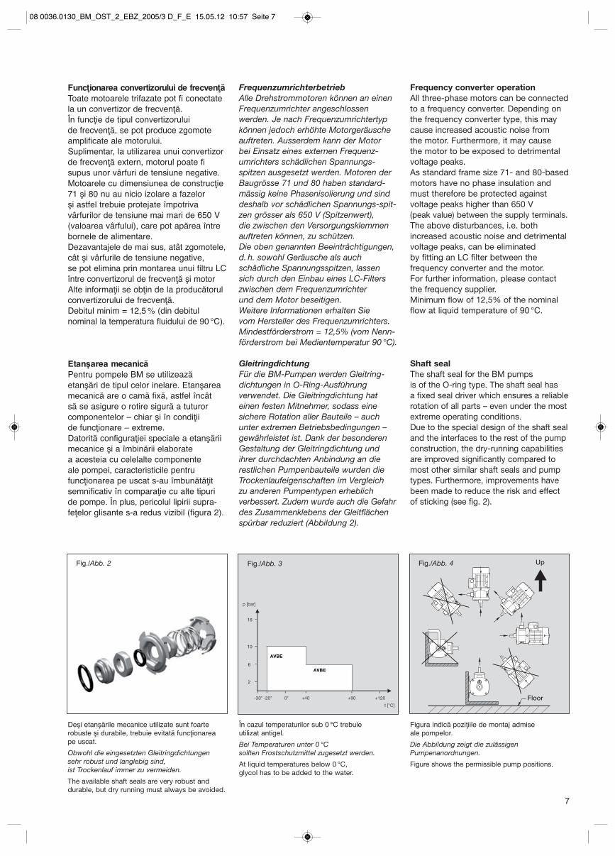
Figura indică poziţiile de montaj admise ale pompelor.
Die Abbildung zeigt die zulässigenPumpenanordnungen.
Figure shows the permissible pump positions.
Deşi etanşările mecanice utilizate sunt foarterobuste şi durabile, trebuie evitată funcţionarea pe uscat.
Obwohl die eingesetzten Gleitringdichtungen sehr robust und langlebig sind, ist Trockenlauf immer zu vermeiden.
The available shaft seals are very robust and durable, but dry running must always be avoided.
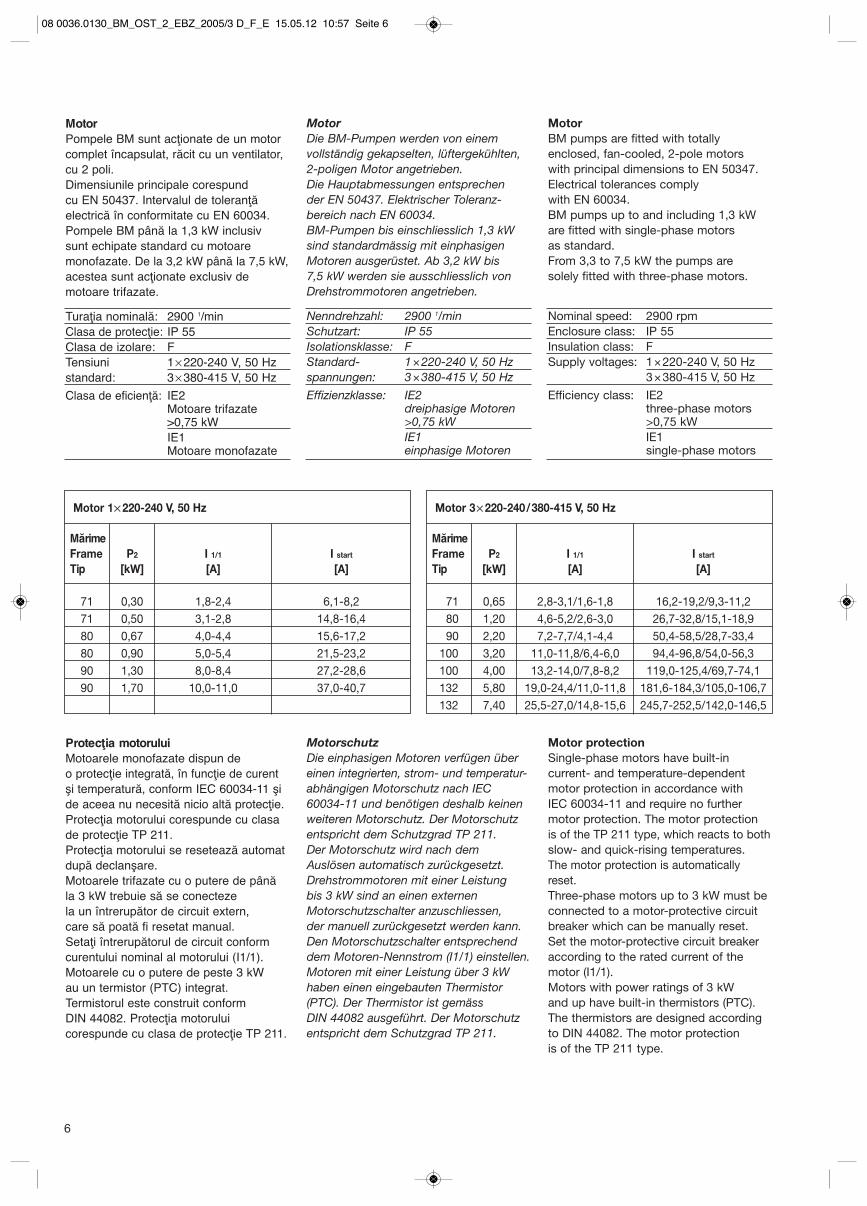
În cazul temperaturilor sub 0 °C trebuie utilizat antigel.
Bei Temperaturen unter 0 °C sollten Frostschutzmittel zugesetzt werden.
At liquid temperatures below 0 °C, glycol has to be added to the water.
Fig./Abb. 4Fig./Abb. 2 Fig./Abb. 3
08 0036.0130_BM_OST_2_EBZ_2005/3 D_F_E 15.05.12 10:57 Seite 7
Intervalul de funcţionare al etanşării mecaniceIntervalul de funcţionare al etanşăriimecanice depinde de presiunea defuncţionare, de tipul etanşării mecanice şi de temperatura fluidului. Diagrama dinfig. 3 indică ce etanşare mecanică esteadecvată în funcţie de temperatura fluidului şi presiunea de funcţionare.Diagrama este valabilă pentru apa curată.
Montarea pompeiPompa de amplasează după cum urmează:– într-un loc bine ventilat – pe o suprafaţă plană– orificiul pentru evacuarea apei trebuie
să fie orientat în jos, pentru a evita pătrunderea aerului în carcasa pompei şi în conducte
– trebuie asigurat accesul uşor pentru lucrările de control, întreţinere şi service
– pompa trebuie fixată pentru a se evita deplasarea în timpul pornirii şi al funcţionării
– poziţia de montaj admisă a pompelor, vezi figura 4.
Betriebsbereich der GleitringdichtungDer Betriebsbereich der Gleitringdichtungist abhängig von dem Betriebsdruck, der verwendeten Gleitringdichtung undder Medientemperatur. Das Diagramm inAbb. 3 zeigt, welche Gleitringdichtung fürwelche Medientemperatur und welchenBetriebsdruck geeignet ist. Das Diagrammgilt für klares Wasser.
Aufstellung der PumpeDie Pumpe ist wie folgt aufzustellen:– an einem gut belüfteten Ort – auf einer ebenen Fläche– die Entwässerungsbohrung sollen
nach unten weisen, um Lufteinschlüsse im Pumpengehäuse und den Rohr-leitungen zu vermeiden
– ein einfacher Zugang für Inspektions-, Wartungs- und Servicearbeiten muss gewährleistet sein
– die Befestigung der Pumpe muss ein Verschieben während der Inbetrieb-nahme und des Betriebs verhindern
– zulässige Pumpenanordnung siehe Abbildung 4
Maximum operating pressure and permissible liquid temperatureThe maximum operating pressure and the permissible liquid temperaturedepend on the pump material, the type of shaft seal and the pumped liquid.The curve in fig. 3 shows which shaftseals are suitable at a given temperatureand a given pressure.
Installation of pumpThe pump has to be installed:– in a well-ventilated location– on a plane surface so that air locks
are avoided in the pump housing and pipework
– an easy access for inspection, maintenance and service must be ensured
– the pump must be fixed so that it cannot be displaced during start-up and operation
– fig. 4 shows the permissible pump positions
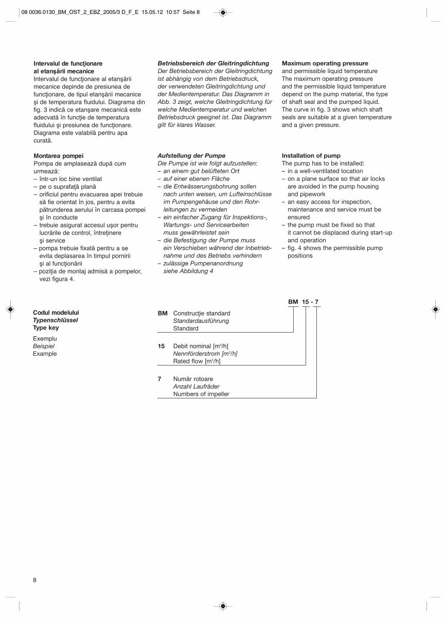
Codul modeluluiTypenschlüsselType key
ExempluBeispielExample
BM Construcţie standardStandardausführungStandard
15 Debit nominal [m3/h]Nennförderstrom [m3/h]Rated flow [m3/h]
7 Număr rotoareAnzahl LaufräderNumbers of impeller
BM 15 - 7
8
08 0036.0130_BM_OST_2_EBZ_2005/3 D_F_E 15.05.12 10:57 Seite 8
9
Presiunea de admisie minimă, NPSHSe recomandă calcularea presiunii preliminare „H”– la temperaturi înalte ale fluidului– dacă debitul depăşeşte semnificativ
debitul nominal al pompei– dacă apa este pompată
de la mare adâncime– în cazul transportului apei
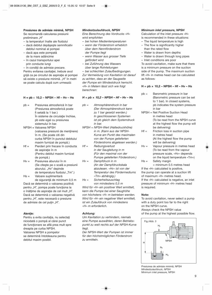
prin conducte lungi– în condiţii de admisie precare.Pentru evitarea cavitaţiei, trebuie avutgrijă ca pe circuitul de aspiraţie al pompeisă existe o presiune minimă. „H” în metrise poate calcula după cum urmează:
H = pb × 10,2 – NPSH – Hf – Hv – Hs
pb = Presiunea atmosferică în bar (Presiunea atmosferică poate fi setată la 1 bar.)În sisteme de circulaţie închise, pb este egal cu presiunea sistemului în bar.
NPSH = Valoarea NPSH (valoarea presiunii de menţinere) în m. (Se poate citi dincurba NPSH în punctul debitului maxim furnizat de pompă.)
Hf = Pierderi prin frecare în conducta de aspiraţie în m (Pentru debitul maxim furnizat de pompă.)
Hv = Presiunea aburului în m(Se citeşte pe o scală a presiunii aburului. „Hv” depinde de temperatura fluidului „Tm”.)
Hs = Valoare suplimentară de siguranţă de minimum 0,5 m
Dacă se determină o valoarea pozitivăpentru „H”, pompa poate funcţiona la o înălţime de aspiraţie de cel mult „H”.Dacă se determină o valoarea negativăpentru „H”, este necesară o presiune de admisie de cel puţin „H”.
Atenţie: Pentru a evita cavitaţia, nu selectaţi niciodată o pompă al cărei punct de funcţionare se află prea mult spre dreapta pe curba NPSH.Valoarea NPSH a pompelor se determină întotdeauna pentru debitul maxim posibil.
Mindestzulaufdruck, NPSHEine Berechnung des Vordrucks «H» wird empfohlen– bei hohen Medientemperaturen– wenn der Förderstrom erheblich
über dem Nennförderstrom der Pumpe liegt
– wenn Wasser aus grosser Tiefe gefördert wird
– bei Zuführung des Wassers über lange Rohrleitungen
– bei schlechten Zulaufbedingungen.Zur Vermeidung von Kavitation ist daraufzu achten, dass an der Saugseite der Pumpe ein Mindestdruck herrscht.«H» in Metern lässt sich wie folgt berechnen:
H = pb × 10,2 – NPSH – Hf – Hv – Hs
pb = Atmosphärendruck in bar(Der Atmosphärendruck kann zu 1 bar gesetzt werden.)In geschlossenen Systemen ist pb gleich dem Systemdruck in bar.
NPSH = NPSH-Wert (Haltedruckhöhe) in m. (Kann aus der NPSH-Kurve am Punkt des maximalen von der Pumpe gelieferten Förderstroms abgelesen werden.)
Hf = Reibungsverlust in der Saugleitung in m(Für den maximal von der Pumpe gelieferten Förderstrom.)
Hv = Dampfdruck in m(An der Dampfdruckskala abzulesen. «Hv» ist von der Temperatur des Fördermediums «Tm» abhängig.)
Hs = Sicherheitszuschlag von mindestens 0,5 m
Wird für «H» ein positiver Wert ermittelt,kann die Pumpe bei einer Saughöhe von höchstens «H» m betrieben werden.Wird für «H» ein negativer Wert ermittelt,ist ein Zulaufdruck von mindestens «H» m erforderlich.
Achtung: Um Kavitation zu verhindern, niemalseine Pumpe auswählen, deren Betriebs-punkt zu weit rechts auf der NPSH-Kurveliegt.Der NPSH-Wert der Pumpen ist immerfür den höchstmöglichen Förderstrom zu ermitteln. NPSH
H
Hf
pb
HV
Presiunea de admisie minimă, NPSHMindestzulaufdruck, NPSH Minimum inlet pressure, NPSH
Fig./Abb. 5
Minimum inlet pressure, NPSHCalculation of the inlet pressure «H» is recommended in these situations:– The liquid temperature is high– The flow is significantly higher
than the rated flow– Water is drawn from depths– Water is drawn through long pipes– Inlet conditions are poorTo avoid cavitation, make sure that thereis a minimum pressure on the suctionside of the pump. The maximum suctionlift «H» in metres head can be calculatedas follows:
H = pb × 10,2 – NPSH – Hf – Hv – Hs
pb = Barometric pressure in bar(Barometric pressure can be set to 1 bar). In closed systems, pb indicates the system pressurein bar
NPSH = Net Positive Suction Head in metres head(To be read from the NPSH curveat the highest flow the pump will be delivering)
Hf = Friction loss in suction pipe in metres head (At the highest flow the pump will be delivering)
Hv = Vapour pressure in metres head (To be read from the vapour pressure scale, «Hv» depends on the liquid temperature «Tm»)
Hs = Safety margin = minimum 0.5 metres head
If the «H» calculated is positive, the pump can operate at a suction lift of maximum «H» metres head.If the «H» calculated is negative, an inletpressure of minimum «H» metres head is required.
Note: To avoid cavitation, never select a pumpwith a duty point too far to the right on the NPSH curve.Always check the NPSH value of the pump at the highest possible flow.
08 0036.0130_BM_OST_2_EBZ_2005/3 D_F_E 15.05.12 10:57 Seite 9
10
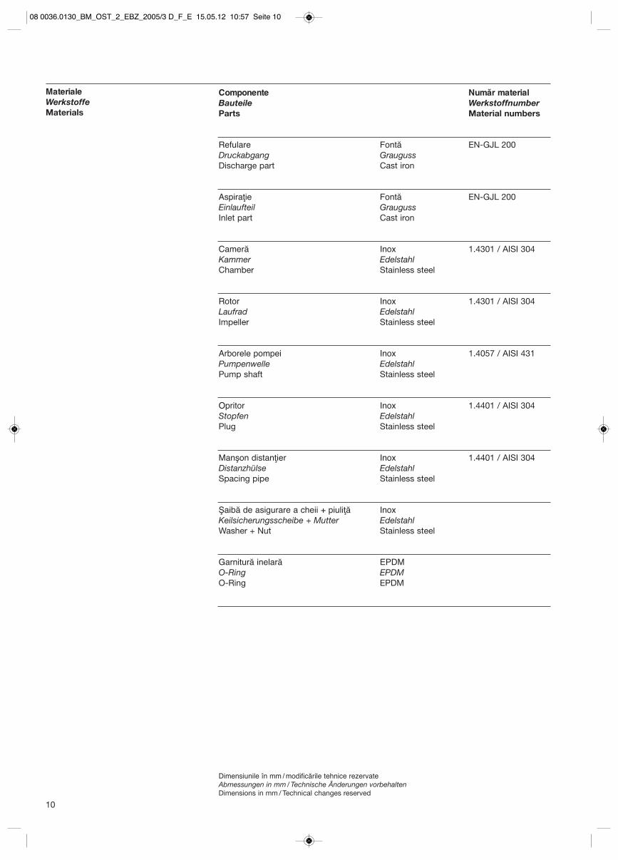
Componente Număr materialBauteile WerkstoffnumberParts Material numbers
Refulare Fontă EN-GJL 200Druckabgang GraugussDischarge part Cast iron
Aspiraţie Fontă EN-GJL 200Einlaufteil GraugussInlet part Cast iron
Cameră Inox 1.4301 / AISI 304Kammer EdelstahlChamber Stainless steel
Rotor Inox 1.4301 / AISI 304Laufrad EdelstahlImpeller Stainless steel
Arborele pompei Inox 1.4057 / AISI 431Pumpenwelle EdelstahlPump shaft Stainless steel
Opritor Inox 1.4401 / AISI 304Stopfen EdelstahlPlug Stainless steel
Manşon distanţier Inox 1.4401 / AISI 304Distanzhülse EdelstahlSpacing pipe Stainless steel
Şaibă de asigurare a cheii + piuliţă InoxKeilsicherungsscheibe + Mutter EdelstahlWasher + Nut Stainless steel
Garnitură inelară EPDMO-Ring EPDMO-Ring EPDM
MaterialeWerkstoffeMaterials
Dimensiunile în mm / modificările tehnice rezervateAbmessungen in mm / Technische Änderungen vorbehaltenDimensions in mm / Technical changes reserved
08 0036.0130_BM_OST_2_EBZ_2005/3 D_F_E 15.05.12 10:57 Seite 10
11
BM
1
BM
3
BM
5
BM
10
BM
15
BM
25
Q [m3/h]
Q [l/s]
H[m]
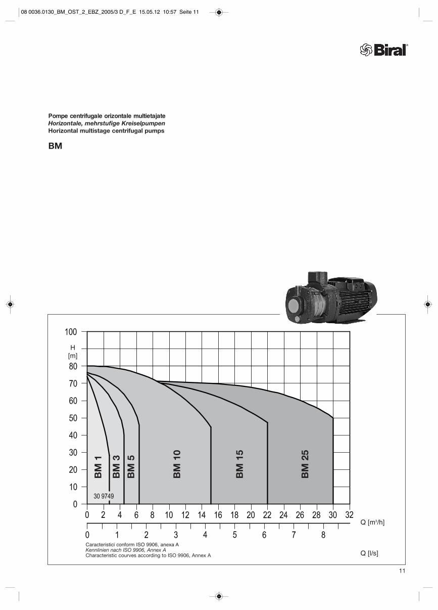
Pompe centrifugale orizontale multietajateHorizontale, mehrstufige KreiselpumpenHorizontal multistage centrifugal pumps
BM
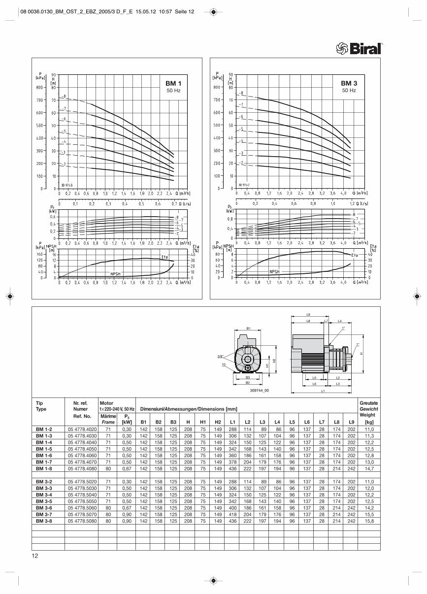
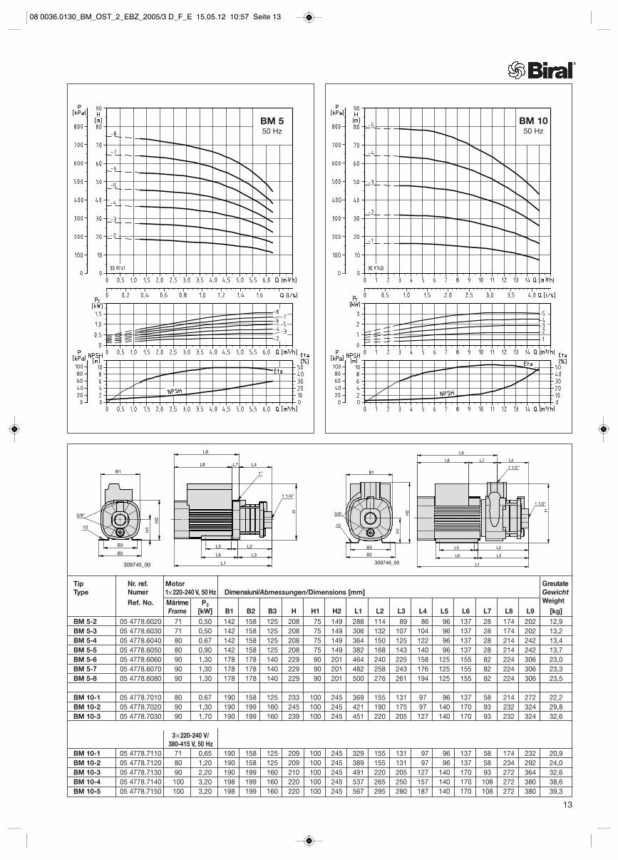
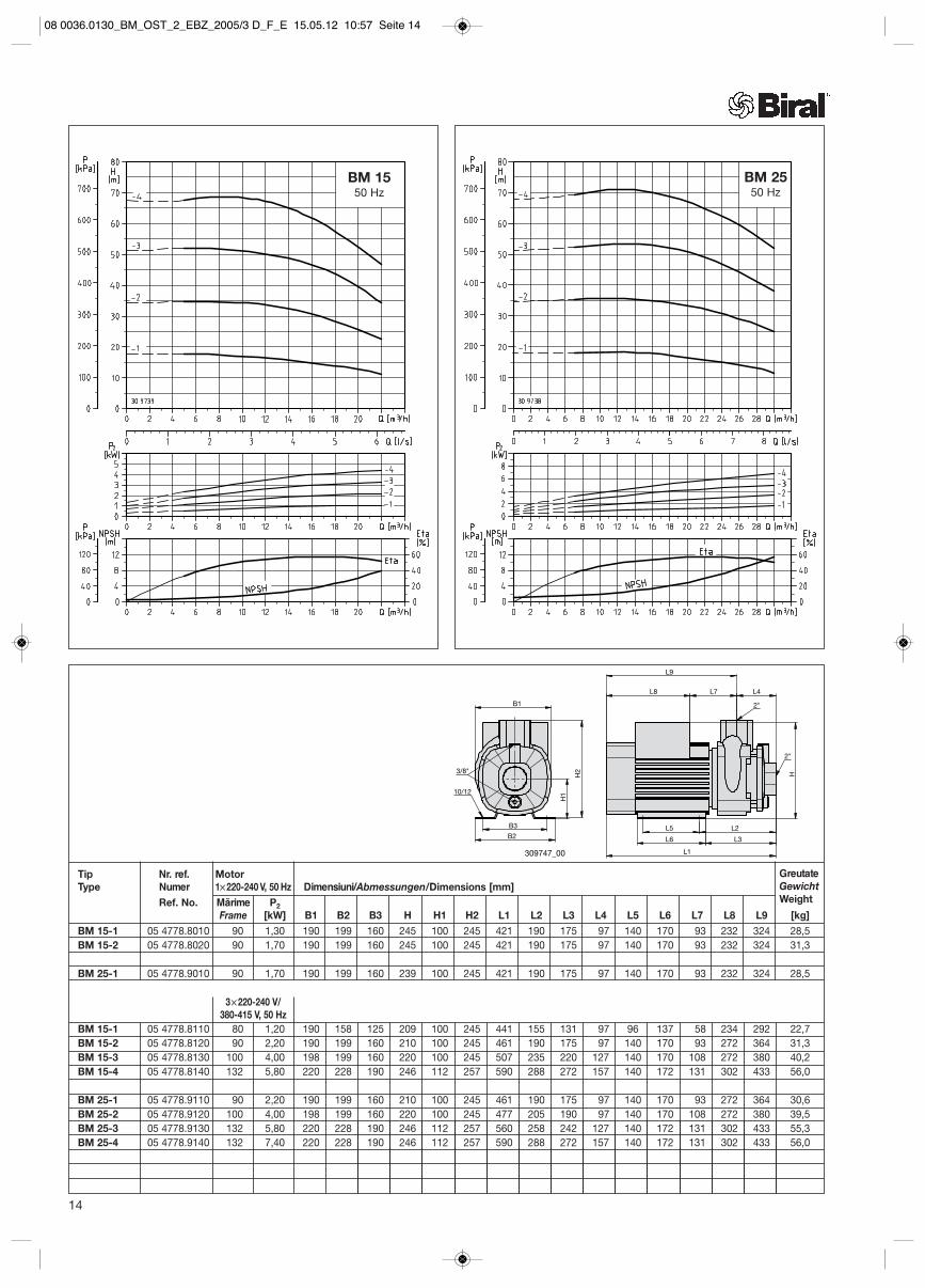
Caracteristici conform ISO 9906, anexa AKennlinien nach ISO 9906, Annex ACharacteristic courves according to ISO 9906, Annex A
08 0036.0130_BM_OST_2_EBZ_2005/3 D_F_E 15.05.12 10:57 Seite 11
12
L6 L3
L1
L4L7L8
L9
H
L5 L2
1"
1"
B3
B2
B1
H1
H2
309744_00
10
3/8"
Tip Nr. ref. MotorType Numer 1× 220-240 V, 50 Hz Dimensiuni/Abmessungen/Dimensions [mm]
Ref. No. Mărime P2Frame [kW] B1 B2 B3 H H1 H2 L1 L2 L3 L4 L5 L6 L7 L8 L9 [kg]
BM 1-2 05 4778.4020 71 0,30 142 158 125 208 75 149 288 114 89 86 96 137 28 174 202 11,0BM 1-3 05 4778.4030 71 0,30 142 158 125 208 75 149 306 132 107 104 96 137 28 174 202 11,3BM 1-4 05 4778.4040 71 0,50 142 158 125 208 75 149 324 150 125 122 96 137 28 174 202 12,2BM 1-5 05 4778.4050 71 0,50 142 158 125 208 75 149 342 168 143 140 96 137 28 174 202 12,5BM 1-6 05 4778.4060 71 0,50 142 158 125 208 75 149 360 186 161 158 96 137 28 174 202 12,8BM 1-7 05 4778.4070 71 0,50 142 158 125 208 75 149 378 204 179 176 96 137 28 174 202 13,0BM 1-8 05 4778.4080 80 0,67 142 158 125 208 75 149 436 222 197 194 96 137 28 214 242 14,7
BM 3-2 05 4778.5020 71 0,30 142 158 125 208 75 149 288 114 89 86 96 137 28 174 202 11,0BM 3-3 05 4778.5030 71 0,50 142 158 125 208 75 149 306 132 107 104 96 137 28 174 202 12,0BM 3-4 05 4778.5040 71 0,50 142 158 125 208 75 149 324 150 125 122 96 137 28 174 202 12,2BM 3-5 05 4778.5050 71 0,50 142 158 125 208 75 149 342 168 143 140 96 137 28 174 202 12,5BM 3-6 05 4778.5060 80 0,67 142 158 125 208 75 149 400 186 161 158 96 137 28 214 242 14,2BM 3-7 05 4778.5070 80 0,90 142 158 125 208 75 149 418 204 179 176 96 137 28 214 242 15,5BM 3-8 05 4778.5080 80 0,90 142 158 125 208 75 149 436 222 197 194 96 137 28 214 242 15,8
BM 150 Hz
BM 350 Hz
GreutateGewichtWeight
08 0036.0130_BM_OST_2_EBZ_2005/3 D_F_E 15.05.12 10:57 Seite 12
H
L6 L3
L1
L7L8 L4
L9
L5 L2
1 1/4"
1"
B2
H1
H2
B1
B3
309745_00
10
3/8"
Tip Nr. ref. MotorType Numer 1× 220-240 V, 50 Hz Dimensiuni/Abmessungen/Dimensions [mm]
Ref. No. Mărime P2Frame [kW] B1 B2 B3 H H1 H2 L1 L2 L3 L4 L5 L6 L7 L8 L9 [kg]
BM 5-2 05 4778.6020 71 0,50 142 158 125 208 75 149 288 114 89 86 96 137 28 174 202 12,9BM 5-3 05 4778.6030 71 0,50 142 158 125 208 75 149 306 132 107 104 96 137 28 174 202 13,2BM 5-4 05 4778.6040 80 0.67 142 158 125 208 75 149 364 150 125 122 96 137 28 214 242 13,4BM 5-5 05 4778.6050 80 0,90 142 158 125 208 75 149 382 168 143 140 96 137 28 214 242 13,7BM 5-6 05 4778.6060 90 1,30 178 178 140 229 90 201 464 240 225 158 125 155 82 224 306 23,0BM 5-7 05 4778.6070 90 1,30 178 178 140 229 90 201 482 258 243 176 125 155 82 224 306 23,3BM 5-8 05 4778.6080 90 1,30 178 178 140 229 90 201 500 276 261 194 125 155 82 224 306 23,5
BM 10-1 05 4778.7010 80 0.67 190 158 125 233 100 245 369 155 131 97 96 137 58 214 272 22,2BM 10-2 05 4778.7020 90 1,30 190 199 160 245 100 245 421 190 175 97 140 170 93 232 324 29,8BM 10-3 05 4778.7030 90 1,70 190 199 160 239 100 245 451 220 205 127 140 170 93 232 324 32,6
3× 220-240 V/380-415 V, 50 Hz
BM 10-1 05 4778.7110 71 0,65 190 158 125 209 100 245 329 155 131 97 96 137 58 174 232 20,9BM 10-2 05 4778.7120 80 1,20 190 158 125 209 100 245 389 155 131 97 96 137 58 234 292 24,0BM 10-3 05 4778.7130 90 2,20 190 199 160 210 100 245 491 220 205 127 140 170 93 272 364 32,6BM 10-4 05 4778.7140 100 3,20 198 199 160 220 100 245 537 265 250 157 140 170 108 272 380 38,6BM 10-5 05 4778.7150 100 3,20 198 199 160 220 100 245 567 295 280 187 140 170 108 272 380 39,3
H
L7L8
L9
L4
L6 L3
L1
L5 L2
1 1/2"
1 1/2"
B2
H1
H2
B1
B3
309746_00
10
3/8"
BM 550 Hz
BM 1050 Hz
13
GreutateGewichtWeight
08 0036.0130_BM_OST_2_EBZ_2005/3 D_F_E 15.05.12 10:57 Seite 13
H
L8 L7 L4
L9
L6 L3
L1
L5 L2
2"
2"B1
B2
H1
H2
B3
309747_00
10/12
3/8"
Tip Nr. ref. MotorType Numer 1× 220-240 V, 50 Hz Dimensiuni/Abmessungen/Dimensions [mm]
Ref. No. Mărime P2Frame [kW] B1 B2 B3 H H1 H2 L1 L2 L3 L4 L5 L6 L7 L8 L9 [kg]
BM 15-1 05 4778.8010 90 1,30 190 199 160 245 100 245 421 190 175 97 140 170 93 232 324 28,5BM 15-2 05 4778.8020 90 1,70 190 199 160 245 100 245 421 190 175 97 140 170 93 232 324 31,3
BM 25-1 05 4778.9010 90 1,70 190 199 160 239 100 245 421 190 175 97 140 170 93 232 324 28,5
3× 220-240 V/380-415 V, 50 Hz
BM 15-1 05 4778.8110 80 1,20 190 158 125 209 100 245 441 155 131 97 96 137 58 234 292 22,7BM 15-2 05 4778.8120 90 2,20 190 199 160 210 100 245 461 190 175 97 140 170 93 272 364 31,3BM 15-3 05 4778.8130 100 4,00 198 199 160 220 100 245 507 235 220 127 140 170 108 272 380 40,2BM 15-4 05 4778.8140 132 5,80 220 228 190 246 112 257 590 288 272 157 140 172 131 302 433 56,0
BM 25-1 05 4778.9110 90 2,20 190 199 160 210 100 245 461 190 175 97 140 170 93 272 364 30,6BM 25-2 05 4778.9120 100 4,00 198 199 160 220 100 245 477 205 190 97 140 170 108 272 380 39,5BM 25-3 05 4778.9130 132 5,80 220 228 190 246 112 257 560 258 242 127 140 172 131 302 433 55,3BM 25-4 05 4778.9140 132 7,40 220 228 190 246 112 257 590 288 272 157 140 172 131 302 433 56,0
BM 1550 Hz
BM 2550 Hz
14
GreutateGewichtWeight
08 0036.0130_BM_OST_2_EBZ_2005/3 D_F_E 15.05.12 10:57 Seite 14
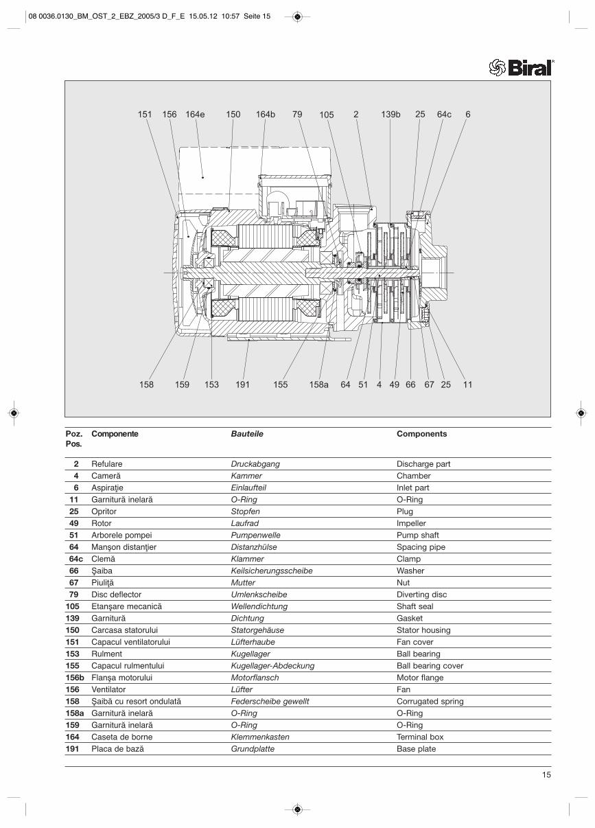
Poz. Componente Bauteile ComponentsPos.
2 Refulare Druckabgang Discharge part4 Cameră Kammer Chamber6 Aspiraţie Einlaufteil Inlet part
11 Garnitură inelară O-Ring O-Ring25 Opritor Stopfen Plug49 Rotor Laufrad Impeller51 Arborele pompei Pumpenwelle Pump shaft64 Manşon distanţier Distanzhülse Spacing pipe64c Clemă Klammer Clamp66 Şaiba Keilsicherungsscheibe Washer67 Piuliţă Mutter Nut79 Disc deflector Umlenkscheibe Diverting disc
105 Etanşare mecanică Wellendichtung Shaft seal139 Garnitură Dichtung Gasket150 Carcasa statorului Statorgehäuse Stator housing151 Capacul ventilatorului Lüfterhaube Fan cover153 Rulment Kugellager Ball bearing155 Capacul rulmentului Kugellager-Abdeckung Ball bearing cover156b Flanşa motorului Motorflansch Motor flange156 Ventilator Lüfter Fan158 Şaibă cu resort ondulată Federscheibe gewellt Corrugated spring158a Garnitură inelară O-Ring O-Ring159 Garnitură inelară O-Ring O-Ring164 Caseta de borne Klemmenkasten Terminal box191 Placa de bază Grundplatte Base plate
15
08 0036.0130_BM_OST_2_EBZ_2005/3 D_F_E 15.05.12 10:57 Seite 15
Biral AG Münsingen, sediul central din Elveţia
Nr.
03/1
2
08 0
036.
0130
_00
rom
/d/e
Biral AGSüdstrasse 10CH-3110 MünsingenT +41 (0) 31 720 90 00F +41 (0) 31 720 94 42E-Mail: [email protected]
Biral GmbHPräzisionspumpenFreiherr-vom-Stein-Weg 15 D-72108 Rottenburg am NeckarT +49 (0) 7472 16 33 0F +49 (0) 7472 16 34 0E-Mail: [email protected]
Biral Pompen B.VPrinterweg 13 3821 APPostbus 2650 3800 GENL-AmersfoortT +31 (0) 33 455 94 44F +31 (0) 33 455 96 10E-Mail: [email protected]
08 0036.0130_BM_OST_2_EBZ_2005/3 D_F_E 15.05.12 10:57 Seite 16