
DESIGNING A PV/FC HYBRID SYSTEM … · Fuel cell converts chemical energy to ... fuel cell acts as...
12
BULETINUL INSTITUTULUI POLITEHNIC DIN IAŞI Publicat de Universitatea Tehnică „Gheorghe Asachi” din Iaşi Tomul LVIII (LXII), Fasc. 2, 2012 SecŃia AUTOMATICĂ şi CALCULATOARE DESIGNING A PV/FC HYBRID SYSTEM CONSIDERING SALE ELECTRICITY BY SABER ARABI NOWDEH ∗ , ABBAS RAJABI-GHAHNAVIEH and AMIN BAZZAZI Department of Electrical Engineering, Behbahan Branch, Islamic Azad University, Behbahan, Iran Received: April 27, 2012 Accepted for publication: May 24, 2012 Abstract. Development of renewable energy sources has shown perfect potential as a form of contribution to conventional power generation systems. This paper presents the design of a hybrid system based on photovoltaic module and a proton exchange membrane fuel cell with the aim of selling electricity to distribution network, while improving its reliability. In this paper the proposed hybrid system supplies load electricity to system and it is capable of selling electricity to the distribution network. The revenue from selling electricity network is considered as system profit. An optimization problem maximizing the system profit is solved by using GAMS software. Hourly rates of electricity sold to the distribution network are determined based on changes in solar irradiance, the rate of proton exchange membrane fuel cell hydrogen consumption and stored hydrogen in the tank. This study shows that electricity can be sold to the distribution network by the proposed hybrid system, and injecting electricity to distribution network in peak time can compensate system costs. Key words: photovoltaic cell, fuel cell, sale electricity, distribution network, GAMS. 2010 Mathematics Subject Classification: 78M50. ∗ Corresponding author; e-mail: [email protected]
Transcript of DESIGNING A PV/FC HYBRID SYSTEM … · Fuel cell converts chemical energy to ... fuel cell acts as...

BULETINUL INSTITUTULUI POLITEHNIC DIN IAŞI Publicat de
Universitatea Tehnică „Gheorghe Asachi” din Iaşi Tomul LVIII (LXII), Fasc. 2, 2012
SecŃia AUTOMATICĂ şi CALCULATOARE
DESIGNING A PV/FC HYBRID SYSTEM CONSIDERING
SALE ELECTRICITY
BY
SABER ARABI NOWDEH∗∗∗∗, ABBAS RAJABI-GHAHNAVIEH
and AMIN BAZZAZI
Department of Electrical Engineering,
Behbahan Branch, Islamic Azad University, Behbahan, Iran
Received: April 27, 2012 Accepted for publication: May 24, 2012
Abstract. Development of renewable energy sources has shown perfect
potential as a form of contribution to conventional power generation systems. This paper presents the design of a hybrid system based on photovoltaic module and a proton exchange membrane fuel cell with the aim of selling electricity to distribution network, while improving its reliability. In this paper the proposed hybrid system supplies load electricity to system and it is capable of selling electricity to the distribution network. The revenue from selling electricity network is considered as system profit. An optimization problem maximizing the system profit is solved by using GAMS software. Hourly rates of electricity sold to the distribution network are determined based on changes in solar irradiance, the rate of proton exchange membrane fuel cell hydrogen consumption and stored hydrogen in the tank. This study shows that electricity can be sold to the distribution network by the proposed hybrid system, and injecting electricity to distribution network in peak time can compensate system costs.
Key words: photovoltaic cell, fuel cell, sale electricity, distribution network, GAMS.
2010 Mathematics Subject Classification: 78M50.
∗Corresponding author; e-mail: [email protected]
Saber Arabi Nowdeh et al.
46
1. Introduction
The need to generate energy by renewable energy sources is increasingly growing, since the demand of electrical energy is expanding due to population growth and industrialization. Concomitantly, the sources of fossil fuels are reducing (Chiu et al., 2004).
Distribution lines cause significant losses, having weak voltage regulation, while low quality and low reliability are the drawbacks of generating energy by conventional methods. These drawbacks can be removed by local energy generation using renewable energy sources, like photovoltaic module, fuel cell and wind turbine. This kind of energy generation is called distributed generation. Some advantages of distributed generation are low distribution losses, better power quality and high reliability. When different kinds of renewable energy sources come together, they generate a hybrid distributed generation system. Photovoltaic generator is one of the proposed sources in this hybrid system.
A photovoltaic module consists of some photovoltaic cells in series or/and parallel. It is one of the renewable energy systems which have always been in the spotlight, and in recent years it has been increasingly expanded on business affairs. Photovoltaic cell directly converts solar radiation energy to electrical energy, and the amount of generated energy changes due to weather condition and level of solar radiation. A photovoltaic module generator has the following drawbacks (Enslin & Snyman, 1991):
− The output voltage versus current follows a nonlinear relation and the photovoltaic cell output power varies with solar radiation. This generated power variation causes disturbances for utility or connected users.
− No power generation is feasible during night hours. − Lack of control for generating power in photovoltaic module leads to
impossibility of scheduling generation for different periods, aspect which is one of the obstacles in business improvements in this technology.
When a photovoltaic module is coupled to a suitable auxiliary energy source, the above drawbacks can be reduced or solved. The auxiliary energy sources that can work in connection with photovoltaic module are fuel cell, wind turbine, battery and diesel generator. Battery is only a low load solution. Wind energy is clean and renewable, but its reliability is low. The diesel generator offers a compact size and high energy density, but it's not clean and renewable, and its running cost is high. Fuel cell converts chemical energy to electrical energy and the amount of power generation can be controlled by regulating the fuel provided for it (natural gas/hydrogen). Fuel cell is an eco-friendly which owns a higher energy density and also can generate power as long as fuel is available. Fuel cell suffers from running cost, but because of higher conversion efficiency, its performance is better when compared to a diesel generator (Kaldellis et al., 2010).
Bul. Inst. Polit. Iaşi, t. LVIII (LXII), f. 2, 2012
47
Fuel cell is capable of generating controlled energy in different periods and can be coupled with photovoltaic module as an auxiliary source. Hence, fuel cell acts as a source of energy storage to compensate the intermittent in power generating of photovoltaic module; as a result, it makes the scheduling of electrical generating possible. Increased profits of generating electrical energy and increasing reliability in providing electrical demand of the consumers are the advantages of simultaneous application of photovoltaic module and fuel cell. From the current discussion, we can conclude that a hybrid distribution generation system consists of photovoltaic and fuel cell sources, and it will result in a desirable system which is capable of providing clean and reliable power round o’clock (Kaldellis et al., 2010).
Investigating related studies, we have observed that the application problem of photovoltaic module and fuel cell in all papers has been with the view of power electronic in order to provide the load power demand (peak-shaving) and load reliability improvement. This problem has never been investigated from the point of view of selling electricity from hybrid system to the distribution network. In this paper, a hybrid system is presented by simultaneous application of a photovoltaic module and a fuel cell. The aim of this study has been maximizing the system profit. When the proposed hybrid system has load electricity provision, it can sale electricity to the distribution network and it can compensate the system costs by the obtained system profit.
2. Proposed Hybrid System Modeling
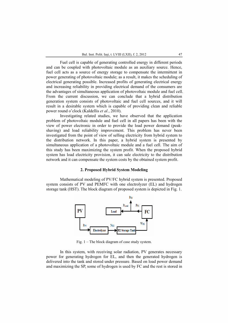
Mathematical modeling of PV/FC hybrid system is presented. Proposed system consists of PV and PEMFC with one electrolyzer (EL) and hydrogen storage tank (HST). The block diagram of proposed system is depicted in Fig. 1.
Fig. 1 – The block diagram of case study system.
In this system, with receiving solar radiation, PV generates necessary power for generating hydrogen for EL, and then the generated hydrogen is delivered into the tank and stored under pressure. Based on load power demand and maximizing the SP, some of hydrogen is used by FC and the rest is stored in
Saber Arabi Nowdeh et al.
48
the tank under pressure. It's worthwhile to mention that the amount of hydrogen stored in the tank is so effective in the amount of SP and that the amount of hydrogen storage depends on tank pressure.
2.1. PV Modeling
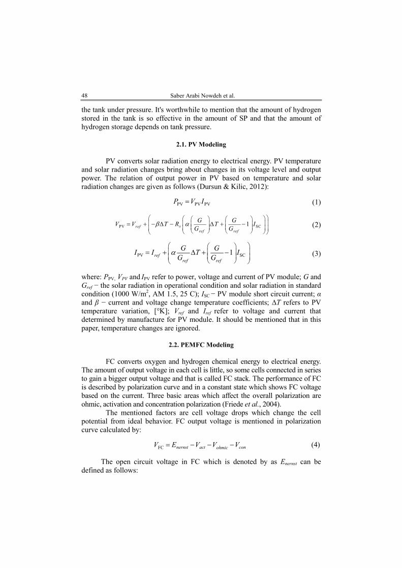
PV converts solar radiation energy to electrical energy. PV temperature and solar radiation changes bring about changes in its voltage level and output power. The relation of output power in PV based on temperature and solar radiation changes are given as follows (Dursun & Kilic, 2012):
PV PV PVP V I= (1)
PV SC1srefref ref
G GV V T R T I
G Gβ α
= + − ∆ − ∆ + −
(2)
PV SC1refref ref
G GI I T I
G Gα
= + ∆ + −
(3)
where: PPV, VPV and IPV refer to power, voltage and current of PV module; G and Gref − the solar radiation in operational condition and solar radiation in standard condition (1000 W/m2, AM 1.5, 25 C); ISC − PV module short circuit current; α and β − current and voltage change temperature coefficients; ∆T refers to PV temperature variation, [°K]; Vref and Iref refer to voltage and current that determined by manufacture for PV module. It should be mentioned that in this paper, temperature changes are ignored.
2.2. PEMFC Modeling
FC converts oxygen and hydrogen chemical energy to electrical energy.
The amount of output voltage in each cell is little, so some cells connected in series to gain a bigger output voltage and that is called FC stack. The performance of FC is described by polarization curve and in a constant state which shows FC voltage based on the current. Three basic areas which affect the overall polarization are ohmic, activation and concentration polarization (Friede et al., 2004).
The mentioned factors are cell voltage drops which change the cell potential from ideal behavior. FC output voltage is mentioned in polarization curve calculated by:
FC nernst act conohmicV E V V V= − − − (4)
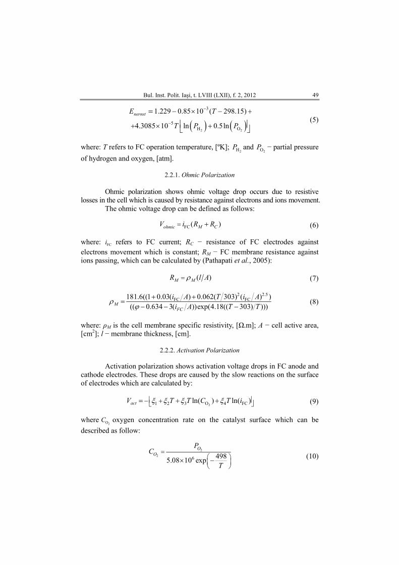
The open circuit voltage in FC which is denoted by as Enernst can be defined as follows:
Bul. Inst. Polit. Iaşi, t. LVIII (LXII), f. 2, 2012
49
( ) ( )2 2
3
5H O
1.229 0.85 10 ( 298.15)
4.3085 10 ln 0.5ln
nernstE T
T P P
−
−
− × − +
+ × +
=
(5)
where: T refers to FC operation temperature, [ºK]; 2HP and
2OP − partial pressure
of hydrogen and oxygen, [atm].
2.2.1. Ohmic Polarization Ohmic polarization shows ohmic voltage drop occurs due to resistive
losses in the cell which is caused by resistance against electrons and ions movement. The ohmic voltage drop can be defined as follows:
FC ( )M CohmicV i R R= + (6)
where: FCi refers to FC current; RC − resistance of FC electrodes against
electrons movement which is constant; RM − FC membrane resistance against ions passing, which can be calculated by (Pathapati et al., 2005):
( )M MR l Aρ= (7)
2 2.5FC FC181.6((1 0.03( ) 0.062( 303) ( ) )
(( 0.634 3( ))exp(4.18(( 303) )))MFC
i A T i A
i A T Tρ
ϕ+ +
=− − − (8)
where: ρM is the cell membrane specific resistivity, [Ω.m]; A − cell active area, [cm2]; l − membrane thickness, [cm].
2.2.2. Activation Polarization
Activation polarization shows activation voltage drops in FC anode and
cathode electrodes. These drops are caused by the slow reactions on the surface of electrodes which are calculated by:
21 2 3 O 4 FCln( ) ln( )actV T T C T iξ ξ ξ ξ − + = + + (9)
where2OC oxygen concentration rate on the catalyst surface which can be
described as follow:
2
26 498
5.08 10 exp
O
O
PC
T
=
× −
(10)
Saber Arabi Nowdeh et al.
50
2.2.3. Concentration Polarization
Concentration polarization shows voltage drop due to reduction in density of reaction materials which is called mass transport losses. To determine voltage drop model in mass transport or concentration voltage drop, maximum current density must be gained (Jmax). Voltage drop corresponding to mass transport can be calculated by (Buasri & Salameh, 2006):
maxln(1 ( ))conV B J J= − − (11)
Considering all FCs voltage drops and for n cells which are connected in series by forming a stack, output power of FC stack is defined as follows:
FC FC FC FCP N V I= ⋅ ⋅ (12) where NFC represents the number of cells in series.
2.2.4. PEMFC Current
The FC current iFC can be determined as a function of hydrogen flow
rate to FC and can be obtained by (El-Sharkh et al., 2004):
2 2FC FC H H(2 )( )i F N W M= (13)
where: WH2 is hydrogen molar flow rate delivered to FC, MH2 is hydrogen molar mass and F refers to Faraday’s constant [C/kmol].
2.3. EL Modeling
Water by EL can be decomposed into its elementary components. This
process is done by passing electrical current between two electrodes that are separated by an aqueous electrolyte. The rate of hydrogen production in an EL is directly proportional to electrical current which is given by (Hedstrom et al., 2004):
2 cH F EL 2N n I Fη= (14) where: ηF refers to Faraday efficiency; nc − number of EL cells in series; IEL −
EL current. The ratio between the real and theoretical maximum amount of hydrogen
which is produced in the EL is called faraday efficiency and defined by:
2(0.09 75.5 )F 96.5 EL ELI Ieη −= (15)
Bul. Inst. Polit. Iaşi, t. LVIII (LXII), f. 2, 2012
51
2.4. HST Modeling
Physical hydrogen storage is one of the storage techniques that use tank
to store compressed hydrogen. After compressing under high pressure, the hydrogen molar flow which is required by PEMFC is sent from the HST. The model of HST is described according to (16) (Hedstrom et al., 2004) and using the ratio of hydrogen flow to the tank, directly obtained the tank pressure.
2 2 2H H H(( ) )b bi b bP P z N W RT M V− = − (16)
where: Pb and Pbi refer to pressure of HST and Initial pressure of the HST, [Pa], respectively; R − universal (Rydberg) gas constant, [J (kmol.ºK)-1]; Z refers to compressibility factor as a function of tank pressure; Tb and Vb represent HST operating temperature, [°K] and volume [m3], respectively.
3. Optimization and Objective Function
PV and FC application with the aim of maximizing SP gained from
generating electrical energy by proposed hybrid system, presenting algorithm for utilization from FC with the aim of maximizing SP, Load and distribution network reliability improvement are the aims of this paper. Equations from (1) to (16) represent the mathematical formulation of case study system. The planning problem is formulated as mixed integer nonlinear programming (MINLP), with an objective function for maximizing the SP due to selling electricity to distribution network.
The objective function is defined as follows:
24
1
( )t
ESMaximize System profit P t=
=∑ (17)
where: PES(t) represents the sold electricity to distribution network (Wh) from proposed hybrid system and is given by:
( ) ( ) ( )ES FC LoadP t P t P t= − (18)
where: PFC(t) and PLoad(t) refer to electricity generated by PEMFC and load electricity demand, respectively.
3.1. Constraints
Optimization problem constraints are as follows:
PFC(t) > PLoad(t) (19)
Saber Arabi Nowdeh et al.
52
PFC(t),min < PFC(t) < PFC(t),max (20)
HST pressure (PHST) must reach to its maximum rate for once during 24 h. Also following is HST pressure variation domain:
Pmin ≤ PHST ≤ Pmax (21)
3.2. System Input Data
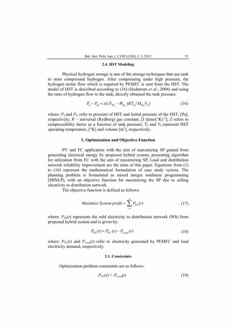
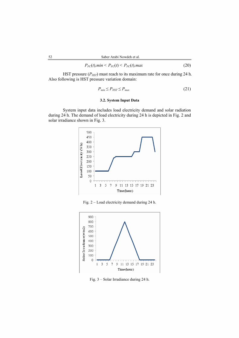
System input data includes load electricity demand and solar radiation
during 24 h. The demand of load electricity during 24 h is depicted in Fig. 2 and solar irradiance shown in Fig. 3.
Fig. 2 – Load electricity demand during 24 h.
Fig. 3 – Solar Irradiance during 24 h.
Bul. Inst. Polit. Iaşi, t. LVIII (LXII), f. 2, 2012
53
4. Optimization Results and Discussion
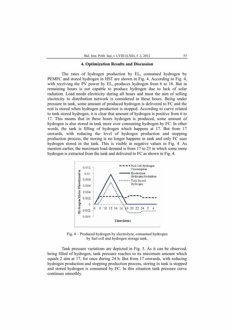
The rates of hydrogen production by EL, consumed hydrogen by
PEMFC and stored hydrogen in HST are shown in Fig. 4. According to Fig. 4, with receiving the PV power by EL, produces hydrogen from 6 to 18. But in remaining hours is not capable to produce hydrogen due to lack of solar radiation. Load needs electricity during all hours and must the aim of selling electricity to distribution network is considered in these hours. Being under pressure in tank, some amount of produced hydrogen is delivered to FC and the rest is stored when hydrogen production is stopped. According to curve related to tank stored hydrogen, it is clear that amount of hydrogen is positive from 6 to 17. This means that in these hours hydrogen is produced, some amount of hydrogen is also stored in tank more over consuming hydrogen by FC. In other words, the tank is filling of hydrogen which happens at 17. But from 17 onwards, with reducing the level of hydrogen production and stopping production process, the storing is no longer happens in tank and only FC uses hydrogen stored in the tank. This is visible in negative values in Fig. 4. As mention earlier, the maximum load demand is from 17 to 23 in which some more hydrogen is extracted from the tank and delivered to FC as shown in Fig. 4.
Fig. 4 – Produced hydrogen by electrolyze, consumed hydrogen by fuel cell and hydrogen storage tank.
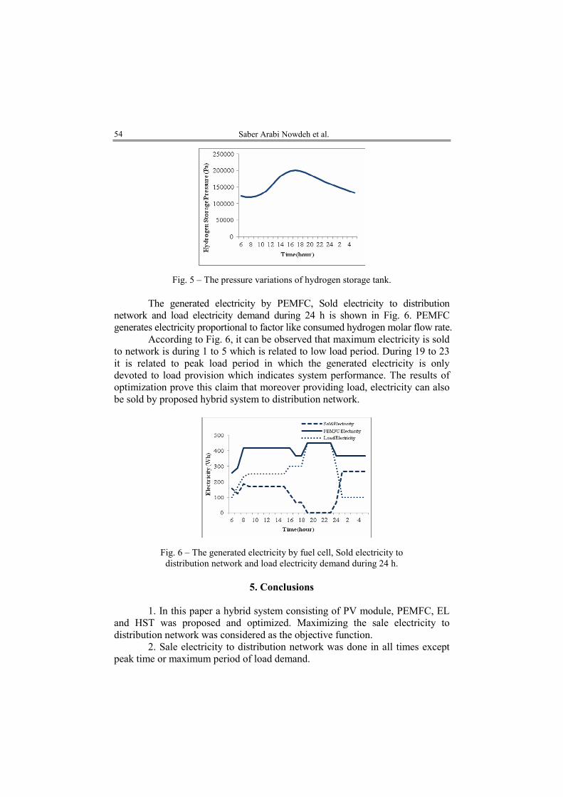
Tank pressure variations are depicted in Fig. 5. As it can be observed,
being filled of hydrogen, tank pressure reaches to its maximum amount which equals 2 atm at 17, for once during 24 h. But from 17 onwards, with reducing hydrogen production and stopping production process, storing in tank is stopped and stored hydrogen is consumed by FC. In this situation tank pressure curve continues smoothly.
Saber Arabi Nowdeh et al.
54
Fig. 5 – The pressure variations of hydrogen storage tank.
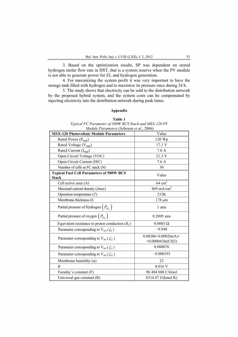
The generated electricity by PEMFC, Sold electricity to distribution network and load electricity demand during 24 h is shown in Fig. 6. PEMFC generates electricity proportional to factor like consumed hydrogen molar flow rate.
According to Fig. 6, it can be observed that maximum electricity is sold to network is during 1 to 5 which is related to low load period. During 19 to 23 it is related to peak load period in which the generated electricity is only devoted to load provision which indicates system performance. The results of optimization prove this claim that moreover providing load, electricity can also be sold by proposed hybrid system to distribution network.
Fig. 6 – The generated electricity by fuel cell, Sold electricity to distribution network and load electricity demand during 24 h.
5. Conclusions
1. In this paper a hybrid system consisting of PV module, PEMFC, EL
and HST was proposed and optimized. Maximizing the sale electricity to distribution network was considered as the objective function.
2. Sale electricity to distribution network was done in all times except peak time or maximum period of load demand.
Bul. Inst. Polit. Iaşi, t. LVIII (LXII), f. 2, 2012
55
3. Based on the optimization results, SP was dependent on stored hydrogen molar flow rate in HST, that is a system reserve when the PV module is not able to generate power for EL and hydrogen generation.
4. For maximizing the system profit it was very important to have the storage tank filled with hydrogen and to maximize its pressure once during 24 h.
5. The study shows that electricity can be sold to the distribution network by the proposed hybrid system, and the system costs can be compensated by injecting electricity into the distribution network during peak times.
Appendix
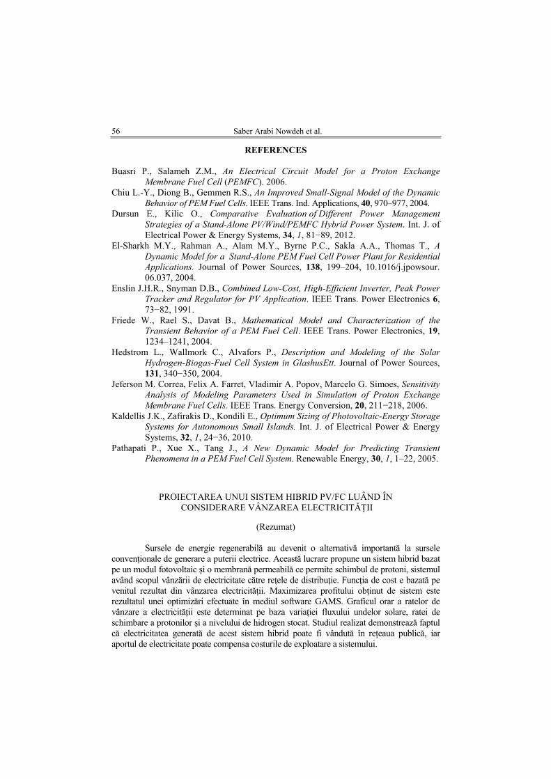
Table 1
Typical FC Parameter of 500W BCS Stack and MSX-120 PV
Module Parameters (Jeferson et al., 2006) MSX-120 Photovoltaic Module Parameters Value
Rated Power (Pmpp) 120 Wp
Rated Voltage (Vmpp) 17.1 V
Rated Current (Impp) 7.0 A
Open Circuit Voltage (VOC) 21.3 V
Open Circuit Current (ISC) 7.6 A
Number of cells in FC stack (N) 30
Typical Fuel Cell Parameters of 500W BCS
Stack Value
Cell active area (A) 64 cm2
Maximal current density (Jmax) 469 mA/cm2
Operation temperature (T) 333K
Membrane thickness (l) 178 µm
Partial pressure of Hydrogen ( )2HP 1 atm
Partial pressure of oxygen ( )2OP 0.2095 atm
Equivalent resistance to proton conduction (RC) 0.0003 Ω
Parameter corresponding to Vact ( 1ξ ) −0.948
Parameter corresponding to Vact ( 2ξ ) 0.00286+0.0002ln(A)+ +0.000043ln(CH2)
Parameter corresponding to Vact ( 3ξ ) 0.000076
Parameter corresponding to Vact ( 4ξ ) −0.000193
Membrane humidity (φ) 23
B 0.016 V
Faraday’s constant (F) 96 484 600 C/kmol
Universal gas constant (R) 8314.47 J/(kmol K)
Saber Arabi Nowdeh et al.
56
REFERENCES
Buasri P., Salameh Z.M., An Electrical Circuit Model for a Proton Exchange
Membrane Fuel Cell (PEMFC). 2006. Chiu L.-Y., Diong B., Gemmen R.S., An Improved Small-Signal Model of the Dynamic
Behavior of PEM Fuel Cells. IEEE Trans. Ind. Applications, 40, 970–977, 2004. Dursun E., Kilic O., Comparative Evaluation of Different Power Management
Strategies of a Stand-Alone PV/Wind/PEMFC Hybrid Power System. Int. J. of Electrical Power & Energy Systems, 34, 1, 81−89, 2012.
El-Sharkh M.Y., Rahman A., Alam M.Y., Byrne P.C., Sakla A.A., Thomas T., A
Dynamic Model for a Stand-Alone PEM Fuel Cell Power Plant for Residential
Applications. Journal of Power Sources, 138, 199–204, 10.1016/j.jpowsour. 06.037, 2004.
Enslin J.H.R., Snyman D.B., Combined Low-Cost, High-Efficient Inverter, Peak Power
Tracker and Regulator for PV Application. IEEE Trans. Power Electronics 6, 73−82, 1991.
Friede W., Rael S., Davat B., Mathematical Model and Characterization of the
Transient Behavior of a PEM Fuel Cell. IEEE Trans. Power Electronics, 19, 1234–1241, 2004.
Hedstrom L., Wallmork C., Alvafors P., Description and Modeling of the Solar
Hydrogen-Biogas-Fuel Cell System in GlashusEtt. Journal of Power Sources, 131, 340−350, 2004.
Jeferson M. Correa, Felix A. Farret, Vladimir A. Popov, Marcelo G. Simoes, Sensitivity
Analysis of Modeling Parameters Used in Simulation of Proton Exchange
Membrane Fuel Cells. IEEE Trans. Energy Conversion, 20, 211−218, 2006. Kaldellis J.K., Zafirakis D., Kondili E., Optimum Sizing of Photovoltaic-Energy Storage
Systems for Autonomous Small Islands. Int. J. of Electrical Power & Energy Systems, 32, 1, 24−36, 2010.
Pathapati P., Xue X., Tang J., A New Dynamic Model for Predicting Transient
Phenomena in a PEM Fuel Cell System. Renewable Energy, 30, 1, 1–22, 2005.
PROIECTAREA UNUI SISTEM HIBRID PV/FC LUÂND ÎN CONSIDERARE VÂNZAREA ELECTRICITĂłII
(Rezumat)
Sursele de energie regenerabilă au devenit o alternativă importantă la sursele
convenŃionale de generare a puterii electrice. Această lucrare propune un sistem hibrid bazat pe un modul fotovoltaic şi o membrană permeabilă ce permite schimbul de protoni, sistemul având scopul vânzării de electricitate către reŃele de distribuŃie. FuncŃia de cost e bazată pe venitul rezultat din vânzarea electricităŃii. Maximizarea profitului obŃinut de sistem este rezultatul unei optimizări efectuate în mediul software GAMS. Graficul orar a ratelor de vânzare a electricităŃii este determinat pe baza variaŃiei fluxului undelor solare, ratei de schimbare a protonilor şi a nivelului de hidrogen stocat. Studiul realizat demonstrează faptul că electricitatea generată de acest sistem hibrid poate fi vândută în reŃeaua publică, iar aportul de electricitate poate compensa costurile de exploatare a sistemului.